EP1213385A2 - Procédé et dispositif pour amener en particulier des pièces de linge à un appareil de traitement - Google Patents
Procédé et dispositif pour amener en particulier des pièces de linge à un appareil de traitement Download PDFInfo
- Publication number
- EP1213385A2 EP1213385A2 EP01124833A EP01124833A EP1213385A2 EP 1213385 A2 EP1213385 A2 EP 1213385A2 EP 01124833 A EP01124833 A EP 01124833A EP 01124833 A EP01124833 A EP 01124833A EP 1213385 A2 EP1213385 A2 EP 1213385A2
- Authority
- EP
- European Patent Office
- Prior art keywords
- loading
- clamps
- laundry
- clips
- brackets
- Prior art date
- Legal status (The legal status is an assumption and is not a legal conclusion. Google has not performed a legal analysis and makes no representation as to the accuracy of the status listed.)
- Granted
Links
Images


Classifications
-
- D—TEXTILES; PAPER
- D06—TREATMENT OF TEXTILES OR THE LIKE; LAUNDERING; FLEXIBLE MATERIALS NOT OTHERWISE PROVIDED FOR
- D06F—LAUNDERING, DRYING, IRONING, PRESSING OR FOLDING TEXTILE ARTICLES
- D06F67/00—Details of ironing machines provided for in groups D06F61/00, D06F63/00, or D06F65/00
- D06F67/04—Arrangements for feeding or spreading the linen
Definitions
- the invention relates to a method for feeding laundry items in particular a treatment device according to the preamble of claim 1. Furthermore The invention relates to a device for feeding items of laundry in particular to a treatment device according to the preamble of claim 7.
- the supply of laundry items to a treatment facility is usually done by manually hanging preferably neighboring ones Corners of a respective item of laundry in loading clips of, for example, one Feed conveyor.
- the item of laundry is then from the loading clamps to the treatment facility or input device transported.
- the Items of laundry on, for example, clips, in particular spreading clips, of the input device or treatment facility.
- a method for solving this problem has the measures of claim 1.
- the or any other The loading clamp of the respective group is then in one of the loading stations away-facing position, in the vicinity of the transfer area. Empty Loading clamps are created by the joint movement of all loading clamps inevitably moved back to the loading station when each one item of laundry holding loading clamps are moved to the transfer area.
- the empty parentheses need only cover a relatively short distance to the loading station, so that in the loading station free loading clamps very quickly To be available.
- the brackets of each group are arranged so that when a part the loading clip is in the loading position, other loading clips in the Transfer area are arranged. It is therefore possible to do this in the shortest possible way Transporting items of laundry from the loading clips to the transfer area, while moving the loading clamps of each group together at the same time empty loading clips are again made available to the loading station.
- the clamps are provided to drive each group all around. This makes it a common one (Only) drive for all clamps in each group or possibly all Multiple groups can be bracketed. Due to the common drive one Synchronization takes place at least the brackets of the respective group, whereby without great mechanical effort is reliably guaranteed that a transfer of the respective items of laundry from the loading clips to the following clips (Spreading clamps) and at the same time empty loading clamps Loading station.
- brackets in particular loading brackets, of each group are provided discontinuously, preferably cyclically. Both downtimes the loading clamps as well as movement phases of the same become. When the loading clamps are at a standstill, they can be loaded in the loading station Corners or corner areas of a new item of laundry can be hooked in manually. While the loading clamps are moving, they move to the following ones Clamps over to the delivery of the respective item of laundry from the loading clips to the following brackets. The different clock phases can thus be used, to either add empty items to laundry clips or the Hand over items of laundry from the loading clips to other clips.
- the clamps are put together according to a preferred method, in particular moved simultaneously or synchronously, on a circular orbit. That kind of movement the loading clip is the easiest and most reliable device-wise realize.
- the clamps especially loading clamps, reoriented during their movement, in particular be pivoted.
- This makes it possible to use the clamps Transfer to the brackets of the input device or the like in another, namely to bring transferable position, while the brackets when moving back to the loading station in a (different) position in which they are in Ergonomically inexpensive way to manually load items of laundry.
- each group is of at least two brackets, in particular Loading clamps, a jointly driven conveyor element of the Feed conveyor assigned.
- Such a group of at least two loading clips serves to hold a corner or a corner area of a preferably upper one Cross edge of the respective item of laundry.
- the laundry items are on two opposite corner areas are held when the treatment facility or the like.
- two groups are preferred two loading clips are provided.
- a conveyor is then available for loading clips.
- These funding bodies will expediently also driven in the same direction. It will not only be loading brackets each group driven together; rather all loading brackets one Station for feeding laundry to the treatment facility or the like, especially a feed conveyor.
- the respective funding body ensures that the clamps, in particular loading clamps, each group are always moved at the same time. It also reduces the Allocation of all loading clips of the respective group to a funding body Number of funding bodies required.
- the loading brackets of each group are, according to a preferred embodiment of the Invention moved by the conveyor on a circular path.
- group with two loading clamps these are arranged at opposite ends of the conveyor element.
- the conveying member can run around a central axis of rotation be driven drivable arm.
- a clip, in particular loading clip is on each of the opposite free ends of the rotary arm a clip, in particular loading clip.
- the respective rotary arm is of such a type assigned to the clamps of an input device or treatment device that the loading clamps moved by the rotating arm on the circular path in the transfer area the clamps of the treatment device or input device are moved past be, the transfer of the laundry, in particular a corner or of a corner area of the same, from the loading clip moved on the circular path the other bracket, which is preferably stationary during this transfer.
- the respective loading clamps then move past the other clamp Mechanically insert the corner area of the item of laundry into the clip mouth of the clip and then the relevant corner area of the item of laundry from the loading clip solved.
- the device according to the invention which is also can act an independent solution to the task mentioned at the outset Clamps, in particular loading clamps, can be pivoted to the Eden of the respective Swivel arm arranged.
- the loading clips are preferably at the ends of the respective pivot arm about pivot axes running parallel to the central axis of rotation pivotable. This allows the insertion direction of a corner area of the Change items of laundry into the clamp jaws of the respective loading clamp so that the corner area of the item of laundry should always be pushed into the clamp mouth can, as is easiest or easiest for operators.
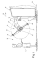
- the device shown in the figures is used to feed items of laundry 10, such as for example tablecloths, sheets or the like, to a defect not shown or another treatment device for the laundry 10.
- the device shown here has two loading stations 11 and 12. Each Loading station 11 and 12 has a feed conveyor 13, 14. Both feed conveyors An input device 15 is assigned to 13 and 14. From the input device 15 individual items of laundry 10 are spread out and a subsequent treatment device, for example, a defect not shown.
- An operator 16 turns on in the area of each loading station 12 or 13 a piece of laundry 10 removed from a laundry pile, not shown, with opposite corner areas of an edge, in particular a leading edge, the Items of laundry 10 in two loading clamps 17 and 18 of the respective feed conveyor 13 or 14 entered.
- the respective feed conveyor 13 or 14 transports this with the Corner areas in the loading clips 17 and 18 hanging laundry item 10 other, in particular following brackets, in the embodiment shown Spreading clamps 19 and 20, respectively, of the input device 15 Transfer of the corner areas of the laundry item 10 from the two loading clips 17 and 18 on two expansion clips 19 and 20.
- the expansion clips 19 and 20 are then move transversely in front of the input device 15, in particular moved apart, stretching the laundry, in particular the front edge of the same between those in the expansion brackets 19 and 20 held corner areas of the laundry 10 takes place. From the spreading clamps 19 or 20 the spread laundry item 10 is then sent to a conveyor of the input device 15 handed over to the laundry 10 in the treatment facility, especially a defect or the like.
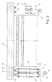
- the device shown here is provided with two loading stations 11 and 12, the opposite sides are assigned to the input device 15. Accordingly two feed conveyors 13 and 14 are assigned to the input device 15, which are each arranged in the area of a loading station 11 and 12.
- the input device 15 has two separate pairs of spreading clamps 19 and 20, whereby a pair of expansion clamps 19 and 20 assigned to a feed conveyor 13 and 14, respectively is. Accordingly, two operators 16 can operate independently of one another at each loading station 11 and 12 the corresponding feed conveyor 13 and 14 load each with a piece of laundry 10.
- each pair of spreading clamps 19 or 20 works Input device 15 independently of one another.
- the Allow single-lane entry alternately one is entered large items of laundry 10 from the spreading clamps 19 or 20 in the area of a loading station 11 or 12 or a feed conveyor 13 or 14.
- the feed conveyors 13 and 14 are designed in a special way, the feed conveyors 13, 14 are identical to one another.
- the invention based on the Feed conveyor 13 explained in more detail.
- the feed conveyor 13 has two equally designed, side by side arranged rotating arms 21.
- Each rotating arm 21 is in a vertical plane, which is in the input direction 23 runs rotatably.
- each rotating arm 21 is on one mounted horizontal axis of rotation 22 which extends transversely to the input direction 23 (Fig. 1).
- the axis of rotation 22 running through the center of the respective rotating arm 21 is formed by a fixed to the rotary arm 21 stub axle 24, which by a suitable Drive, for example an electric motor 25, can be driven.
- the electric motor 25 and the stub axle 24 are mounted on a holding arm 26, which in the embodiment shown is connected to the input device 15. But it is also conceivable the respective feed conveyor 13, ie the stub axle 24 with the rotating arm 21 and the electric motor 25 on a separate frame in front of the input device 15 lagem.
- each of the two parallel rotating arms 21 of the Feed conveyor 13 assigned its own drive.
- each rotating arm 21 is on one own axle stub 24 stored, both on the common, horizontal axis of rotation 22 are in front of the input device 15.
- the drives, in particular Electric motors 25, both rotating arms 21 of the respective feed conveyor 13 are of this type synchronously driven that the rotating arms 21 of the feed conveyor 13 equally move all around.
- both rotating arms 21 of the feed conveyor 13 it is also conceivable for both rotating arms 21 of the feed conveyor 13 to lie on a common axis, rotating by a single drive is drivable, thereby forcing a mechanical coupling of the synchronous operation both rotating arms 21 of the respective feed conveyor 13 is given.
- each rotary arm 21 Opposite, free ends 27 of each rotary arm 21 is a bracket, namely the respective loading clamps 17 and 18 are assigned.
- Each pivot arm 21 has thereby via two opposite loading clamps 17, 18, which are in the embodiment shown are of the same design in a manner known per se, namely for detachable Holding a corner area of the respective laundry 10 serve.
- the axis of rotation 22 is approximately the same size.
- the circular path 28 is in diameter and in position (Position of the axis of rotation 22) so matched to the expansion clamps 19, 20 that the through the insertion opening 29 of the respective jaws of the loading clip 17 or 18 circular path 28 an insertion opening 30 of the staple of relevant expansion bracket 19, 20 cuts (Fig. 1).
- the loading clips 17 and 18 are pivotable at the ends 27 of the respective Swivel arm 21 arranged.
- each loading clip 17, 18 at the end 27 of the respective pivot arm 21 pivotable, namely about a horizontal pivot axis 31, which runs parallel to the axis of rotation 22.
- the distance between the pivot axes 31 at the opposite ends 27 of the rotary arm 21 from the axis of rotation 22 are each approximately the same.
- Each loading clamp 17, 18, which can be pivoted freely about its pivot axis 31 can be brought into the respective swivel position and held in it by one Handlebar arm 32, which is at a distance from the pivot axis 31 on the loading bracket 17th or 18 attacks.
- the ends pointing away from the loading clips 17 and 18 are preferably Handlebar arms 32 of the same length are connected to a swivel gear 33.
- This swivel gear 33 controls the link arms 32 with each rotation of the rotating arm 21 so that the loading clamps 17 and 18 are pivotable relative to the rotating arm 21 are in such a way that the directions of the insertion openings 29 change constantly with the circulation of the loading clamps 17 and 18 on the circular path 28.
- the swivel gear 33 is in the manner of a planetary gear educated.
- a sun gear 34 is concentric with the axis of rotation 22 arranged, which is fixedly connected to the holding arm 26, that is to say with the rotating arm 21 not moved.
- Opposing sides of the sun gear 34 are two the same Planet gears 35 assigned. These are rotatably mounted on the rotating arm 21, and indeed on axes of rotation 39 running parallel to the axis of rotation 22.
- At a distance from the The axis of rotation 39 of each planetary gear 35 is articulated to the respective one Loading clip 17, 18 opposite end of the relevant link arm 32 articulated (Fig. 5).
- the planet gears 35 are in meshing engagement with the Sun gear 34; they are thereby at the rotation of the rotating arm 21 around the stationary Sun gear 34 rotates, which makes it off-center on the respective planet gear 35 mounted end of the handlebar arms 32 on a (small) circular path around the Axis of rotation 39 of the planetary gears 35 moves and thereby displaced in the axial direction becomes, which leads to a pivoting of the loading clamp 17 about the pivot axes 31 leads.
- the swivel gear 33 and the linkages of the link arms 32 to the loading clamps 17 and 18 or the planet wheels 35 are hit so that when moving past a loading clamp 17, 18 on a spreading clamp 19, 20 the insertion opening 29 of the loading clip 17, 18 points approximately vertically downwards and thus rectified to the insertion direction 30 of FIG Spreading bracket 19, 20 is.
- the loading clamp 17, 18 moves past one Spreading clamp 19, 20 thereby becomes the corner region held by the loading clamp 17, 18 of the laundry item 10 into the insertion opening 30 of the spreading clamp 19, 20th moved and at the same time pulled out of the insertion opening 29 of the loading clip 17, 18.
- the corresponding dimensioning of the handlebar arms 32 and Assignment of the same to the planet gears 35 and the loading clamps 17 and 18 that the respective operator 16 loads the Loading clamps 17, 18 with the insertion opening 25 are inclined slightly downwards and are located at an ergonomically favorable height above the floor 36, whereby a simple and fatigue-free loading of the loading clamps 17, 18 with a Laundry 10 for the operator 16 concerned is possible.
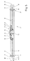
- FIG. 5 shows the loading clips 17 and 18 in plan view. So these are fork-like design with a space 37 between two at a distance in parallel mutually extending clamping portions 38 for the respective corner area of the Items of laundry 10.
- the space 37 between the clamping sections 38 is there dimensioned so that it is slightly larger than the width of the spreading clamps 19 and 20.
- Die Loading clamps 17 and 18 are also relative to the spreading clamps 19 and 20 positioned that those located on opposite sides of the gap 37 Clamping sections 38 of the loading clamps 17 and 18 on the currently stationary Spreading clamps 19 and 20 can be moved past in their takeover position while the loading clamps 17 and 18, the spreading clamps 19 and 20 are collision-free overtake to hand over the corner areas of the laundry item 10 concerned by the Loading clamps 17, 18 to the spreading clamps 19, 20.
- the loading clamps 17 and 18 at opposite ends of the rotating arms 21 about the pivot axes 31 tilted, equally in the opposite direction. So the loading brackets 17 with a piece of laundry 10 when moving from the loading station 11 the spreading clips 19 rotated past such that in the area of the transfer of the Items of laundry 10 from the loading clamps 17 to the spreading clamps 19 the insertion openings 29 of the loading clamps 17 are directed vertically downwards (right Representation of the individual loading clip 17 in Fig. 3).
- the loading clamps 17 and 18 of both rotary arms 21 are pivoted equally controlled by the swivel gear 33 and by this on the Handlebar arms 32 movements in the direction of the loading clips 17 and 18.
- the uniform pivoting of the loading clamps 17 and 18 has both Rotating arms 21 of the feed conveyor 13 result in the leading edge of the laundry item 10 with an adjacent area, in particular the opposite area Corner areas of the front edge of the laundry item 10, corresponding to the pivoting movements the loading clamps 17 and 18 are tilted.
Landscapes
- Engineering & Computer Science (AREA)
- Textile Engineering (AREA)
- Chain Conveyers (AREA)
- Accessory Of Washing/Drying Machine, Commercial Washing/Drying Machine, Other Washing/Drying Machine (AREA)
- Intermediate Stations On Conveyors (AREA)
- Specific Conveyance Elements (AREA)
Applications Claiming Priority (2)
| Application Number | Priority Date | Filing Date | Title |
|---|---|---|---|
| DE2000161103 DE10061103A1 (de) | 2000-12-07 | 2000-12-07 | Verfahren und Vorrichtung zum Zuführen von insbesondere Wäschestücken zu einer Behandlungseinrichtung |
| DE10061103 | 2000-12-07 |
Publications (3)
| Publication Number | Publication Date |
|---|---|
| EP1213385A2 true EP1213385A2 (fr) | 2002-06-12 |
| EP1213385A3 EP1213385A3 (fr) | 2003-07-02 |
| EP1213385B1 EP1213385B1 (fr) | 2005-12-28 |
Family
ID=7666304
Family Applications (1)
| Application Number | Title | Priority Date | Filing Date |
|---|---|---|---|
| EP20010124833 Expired - Lifetime EP1213385B1 (fr) | 2000-12-07 | 2001-10-18 | Procédé et dispositif pour amener des pièces de linge à un appareil de traitement |
Country Status (2)
| Country | Link |
|---|---|
| EP (1) | EP1213385B1 (fr) |
| DE (2) | DE10061103A1 (fr) |
Cited By (3)
| Publication number | Priority date | Publication date | Assignee | Title |
|---|---|---|---|---|
| CN106938780A (zh) * | 2017-04-12 | 2017-07-11 | 清远市星徽精密制造有限公司 | 一种油缸整形送料机构 |
| JP2018015397A (ja) * | 2016-07-29 | 2018-02-01 | 株式会社プレックス | 布類投入機および布類展開装置 |
| EP3361001A1 (fr) * | 2017-02-08 | 2018-08-15 | Herbert Kannegiesser GmbH | Procédé et dispositif de transport et/ou d'étalage des pièces de linge accrochées au moyen des pinces à linge |
Family Cites Families (3)
| Publication number | Priority date | Publication date | Assignee | Title |
|---|---|---|---|---|
| DE3912977C2 (de) * | 1989-04-20 | 2001-04-19 | Kannegiesser H Gmbh Co | Verfahren und Vorrichtung zum Zuführen von Wäschestücken zu einer Mangel |
| JP3150214B2 (ja) * | 1992-11-26 | 2001-03-26 | 株式会社東京洗染機械製作所 | シーツ拡げ機 |
| DE19703587A1 (de) * | 1997-01-31 | 1998-08-06 | Kannegiesser H Gmbh Co | Verfahren und Vorrichtung zum Zuführen von Wäschestücken zu einer Mangel |
-
2000
- 2000-12-07 DE DE2000161103 patent/DE10061103A1/de not_active Withdrawn
-
2001
- 2001-10-18 EP EP20010124833 patent/EP1213385B1/fr not_active Expired - Lifetime
- 2001-10-18 DE DE50108533T patent/DE50108533D1/de not_active Expired - Lifetime
Cited By (5)
| Publication number | Priority date | Publication date | Assignee | Title |
|---|---|---|---|---|
| JP2018015397A (ja) * | 2016-07-29 | 2018-02-01 | 株式会社プレックス | 布類投入機および布類展開装置 |
| EP3361001A1 (fr) * | 2017-02-08 | 2018-08-15 | Herbert Kannegiesser GmbH | Procédé et dispositif de transport et/ou d'étalage des pièces de linge accrochées au moyen des pinces à linge |
| US10400386B2 (en) | 2017-02-08 | 2019-09-03 | Herbert Kannegiesser Gmbh | Method and device for the transport and/or spreading-out of laundry items hung on clamps |
| CN106938780A (zh) * | 2017-04-12 | 2017-07-11 | 清远市星徽精密制造有限公司 | 一种油缸整形送料机构 |
| CN106938780B (zh) * | 2017-04-12 | 2022-11-15 | 清远市星徽精密制造有限公司 | 一种油缸整形送料机构 |
Also Published As
| Publication number | Publication date |
|---|---|
| EP1213385B1 (fr) | 2005-12-28 |
| DE50108533D1 (de) | 2006-02-02 |
| DE10061103A1 (de) | 2002-06-13 |
| EP1213385A3 (fr) | 2003-07-02 |
Similar Documents
| Publication | Publication Date | Title |
|---|---|---|
| DE3930720C1 (fr) | ||
| EP2035283A1 (fr) | Dispositif de traitement de structures tubulaires souples présentant au moins une ouverture | |
| CH634277A5 (de) | Transportvorrichtung fuer plattenfoermige, duenne gegenstaende. | |
| DE1901109A1 (de) | Vorrichtung zum Herstellen und Fuellen von aus einem Band gefalteten Beuteln | |
| DE2751292C2 (de) | Vorrichtung zur Reinigung von einander gegenüberliegenden Filterplatten einer Filterpresse | |
| EP0677610B1 (fr) | Procédé et dispositif pour plier des vêtements | |
| DE3018232C2 (de) | Abgabestation einer Glasformmaschine | |
| EP1213385A2 (fr) | Procédé et dispositif pour amener en particulier des pièces de linge à un appareil de traitement | |
| DE4244827C2 (de) | Vorrichtung zum Zuführen von Wäschestücken zu einer Mangel | |
| DE3240689A1 (de) | Chargiervorrichtung fuer das manipulieren von rohren von stauchpressen | |
| DE2803132C2 (de) | Weitgehend automatisch arbeitende Vorrichtung zum beidseitigen Beschichten von Abstandhalterrahmen für Mehrscheibenisolierglas mit einer Dichtmasse und Verfahren zur Steuerung der Vorrichtung | |
| DE3804791C2 (de) | Vorrichtung zum Auffalten von flachliegenden Hülsen | |
| DE4143070C2 (de) | Verfahren und Vorrichtung zum Zuführen von Wäschestücken zu einer Mangel | |
| EP1911699B1 (fr) | Procédé et dispositif de transmission d'une boucle de transport pour pièces de vêtements sur un convoyeur suivant | |
| DE2325570C2 (de) | Vorrichtung zur Handhabung von im Grundriss eckigen tafelförmigen oder rahmenförmigen Gegenständen | |
| DE2902824A1 (de) | Vorrichtung zur ueberfuehrung von beuteln und deren einfuehrung in schachteln | |
| DE3119418C2 (de) | Übergabevorrichtung beim Transport von Gegenständen zum Aufbringen von Überzügen | |
| DE3242684C2 (de) | Einrichtung f}r die gleichzeitige Herstellung von mehreren Ketten | |
| EP1043251A2 (fr) | Procédé, dispositif et cintre transporteur pour le transfer automatique de cintres | |
| EP3725705A1 (fr) | Dispositif de changement de récipient | |
| DE4134746A1 (de) | Verfahren und vorrichtung zum falten von waeschestuecken | |
| EP3361001B1 (fr) | Procédé et dispositif pour transporter des articles de linge suspendus a des pinces et pour transferer les articles de linge vers un dispositif d'alimentation | |
| DE2731551A1 (de) | Vorrichtung zum zufoerdern von profilstaeben aus stahl | |
| EP2706031B1 (fr) | Dispositif de transmission d'unités de produit entre un convoyeur d'amenée et un convoyeur de sortie | |
| DE19525436C2 (de) | Beschickung eines wenigstens in einem Abschnitt permanent laufenden Fördermittels |
Legal Events
| Date | Code | Title | Description |
|---|---|---|---|
| PUAI | Public reference made under article 153(3) epc to a published international application that has entered the european phase |
Free format text: ORIGINAL CODE: 0009012 |
|
| AK | Designated contracting states |
Kind code of ref document: A2 Designated state(s): AT BE CH CY DE DK ES FI FR GB GR IE IT LI LU MC NL PT SE TR |
|
| AX | Request for extension of the european patent |
Free format text: AL;LT;LV;MK;RO;SI |
|
| RAP1 | Party data changed (applicant data changed or rights of an application transferred) |
Owner name: HERBERT KANNEGIESSER GMBH |
|
| PUAL | Search report despatched |
Free format text: ORIGINAL CODE: 0009013 |
|
| AK | Designated contracting states |
Designated state(s): AT BE CH CY DE DK ES FI FR GB GR IE IT LI LU MC NL PT SE TR |
|
| AX | Request for extension of the european patent |
Extension state: AL LT LV MK RO SI |
|
| 17P | Request for examination filed |
Effective date: 20030616 |
|
| 17Q | First examination report despatched |
Effective date: 20031024 |
|
| AKX | Designation fees paid |
Designated state(s): DE FR GB IT |
|
| RTI1 | Title (correction) |
Free format text: METHOD AND DEVICE FOR FEEDING LAUNDRY PIECES TO A TREATMENT APPARATUS |
|
| GRAP | Despatch of communication of intention to grant a patent |
Free format text: ORIGINAL CODE: EPIDOSNIGR1 |
|
| GRAS | Grant fee paid |
Free format text: ORIGINAL CODE: EPIDOSNIGR3 |
|
| GRAA | (expected) grant |
Free format text: ORIGINAL CODE: 0009210 |
|
| AK | Designated contracting states |
Kind code of ref document: B1 Designated state(s): DE FR GB IT |
|
| PG25 | Lapsed in a contracting state [announced via postgrant information from national office to epo] |
Ref country code: IT Free format text: LAPSE BECAUSE OF FAILURE TO SUBMIT A TRANSLATION OF THE DESCRIPTION OR TO PAY THE FEE WITHIN THE PRESCRIBED TIME-LIMIT;WARNING: LAPSES OF ITALIAN PATENTS WITH EFFECTIVE DATE BEFORE 2007 MAY HAVE OCCURRED AT ANY TIME BEFORE 2007. THE CORRECT EFFECTIVE DATE MAY BE DIFFERENT FROM THE ONE RECORDED. Effective date: 20051228 Ref country code: GB Free format text: LAPSE BECAUSE OF FAILURE TO SUBMIT A TRANSLATION OF THE DESCRIPTION OR TO PAY THE FEE WITHIN THE PRESCRIBED TIME-LIMIT Effective date: 20051228 |
|
| REG | Reference to a national code |
Ref country code: GB Ref legal event code: FG4D Free format text: NOT ENGLISH |
|
| REF | Corresponds to: |
Ref document number: 50108533 Country of ref document: DE Date of ref document: 20060202 Kind code of ref document: P |
|
| GBV | Gb: ep patent (uk) treated as always having been void in accordance with gb section 77(7)/1977 [no translation filed] |
Effective date: 20051228 |
|
| PLBE | No opposition filed within time limit |
Free format text: ORIGINAL CODE: 0009261 |
|
| STAA | Information on the status of an ep patent application or granted ep patent |
Free format text: STATUS: NO OPPOSITION FILED WITHIN TIME LIMIT |
|
| 26N | No opposition filed |
Effective date: 20060929 |
|
| EN | Fr: translation not filed | ||
| PG25 | Lapsed in a contracting state [announced via postgrant information from national office to epo] |
Ref country code: FR Free format text: LAPSE BECAUSE OF FAILURE TO SUBMIT A TRANSLATION OF THE DESCRIPTION OR TO PAY THE FEE WITHIN THE PRESCRIBED TIME-LIMIT Effective date: 20070216 |
|
| PG25 | Lapsed in a contracting state [announced via postgrant information from national office to epo] |
Ref country code: FR Free format text: LAPSE BECAUSE OF FAILURE TO SUBMIT A TRANSLATION OF THE DESCRIPTION OR TO PAY THE FEE WITHIN THE PRESCRIBED TIME-LIMIT Effective date: 20051228 |
|
| PGFP | Annual fee paid to national office [announced via postgrant information from national office to epo] |
Ref country code: DE Payment date: 20141030 Year of fee payment: 14 |
|
| REG | Reference to a national code |
Ref country code: DE Ref legal event code: R119 Ref document number: 50108533 Country of ref document: DE |
|
| PG25 | Lapsed in a contracting state [announced via postgrant information from national office to epo] |
Ref country code: DE Free format text: LAPSE BECAUSE OF NON-PAYMENT OF DUE FEES Effective date: 20160503 |