EP1213498A2 - Bowdenzug mit gelenkig verbundenen Elementen - Google Patents
Bowdenzug mit gelenkig verbundenen Elementen Download PDFInfo
- Publication number
- EP1213498A2 EP1213498A2 EP01128729A EP01128729A EP1213498A2 EP 1213498 A2 EP1213498 A2 EP 1213498A2 EP 01128729 A EP01128729 A EP 01128729A EP 01128729 A EP01128729 A EP 01128729A EP 1213498 A2 EP1213498 A2 EP 1213498A2
- Authority
- EP
- European Patent Office
- Prior art keywords
- cup
- shaped
- control device
- push
- pull
- Prior art date
- Legal status (The legal status is an assumption and is not a legal conclusion. Google has not performed a legal analysis and makes no representation as to the accuracy of the status listed.)
- Withdrawn
Links
Images

Classifications
-
- F—MECHANICAL ENGINEERING; LIGHTING; HEATING; WEAPONS; BLASTING
- F16—ENGINEERING ELEMENTS AND UNITS; GENERAL MEASURES FOR PRODUCING AND MAINTAINING EFFECTIVE FUNCTIONING OF MACHINES OR INSTALLATIONS; THERMAL INSULATION IN GENERAL
- F16C—SHAFTS; FLEXIBLE SHAFTS; ELEMENTS OR CRANKSHAFT MECHANISMS; ROTARY BODIES OTHER THAN GEARING ELEMENTS; BEARINGS
- F16C1/00—Flexible shafts; Mechanical means for transmitting movement in a flexible sheathing
- F16C1/10—Means for transmitting linear movement in a flexible sheathing, e.g. "Bowden-mechanisms"
- F16C1/20—Construction of flexible members moved to and fro in the sheathing
-
- Y—GENERAL TAGGING OF NEW TECHNOLOGICAL DEVELOPMENTS; GENERAL TAGGING OF CROSS-SECTIONAL TECHNOLOGIES SPANNING OVER SEVERAL SECTIONS OF THE IPC; TECHNICAL SUBJECTS COVERED BY FORMER USPC CROSS-REFERENCE ART COLLECTIONS [XRACs] AND DIGESTS
- Y10—TECHNICAL SUBJECTS COVERED BY FORMER USPC
- Y10T—TECHNICAL SUBJECTS COVERED BY FORMER US CLASSIFICATION
- Y10T74/00—Machine element or mechanism
- Y10T74/20—Control lever and linkage systems
- Y10T74/20396—Hand operated
- Y10T74/20402—Flexible transmitter [e.g., Bowden cable]
- Y10T74/20456—Specific cable or sheath structure
Definitions
- This invention refers to mechanical control systems, and more in particular is directed to a control device of the push-pull type, capable of transmitting high pushing and pulling forces between a linear or rotary actuator, such as a pneumatic or hydraulic cylinder or an electric motor, and a mechanical member or device which in turn can be provided with linear or rotary motion, regardless of the type of actuator used.
- a linear or rotary actuator such as a pneumatic or hydraulic cylinder or an electric motor
- control device is particularly suitable for use with remote control systems, in which a movement transmitting line can extend on a surface or in the space along any rectilinear, curved and/or circular path, of any length and in any desired direction.
- the amount of thrust that can be exerted generally proves to be extremely limited since, at the most, it can range from 10 to 20% of the pulling force that can be exerted by the same cable.
- the amount of thrust or pushing force is in any case conditioned by the combined bending and compressive stress acting on the inner cable, as well as by the flexibility of the sheath and the inner cable whose radius of curvature, in general, must be of a considerably high value.
- EP-A-1 059 462 suggests the use of a push-pull device of which the present invention constitutes an improvement.
- EP-A-1 059 462 suggests a push-pull device in which the pushing members are suitably guided over the entire working stroke; nevertheless the pushing members are again in the form of ball or differently shaped members of substantial length or thickness, which do not allow to conform to any force transmitting line having a large amount of flexibility and an extremely reduced bending radius; furthermore the pushing member are again to be manufacture by costly machining operations.
- the general object of this invention is to provide a flexible control system, of the push-pull type, capable of obviating the above mentioned problems inherent in the flexible or articulated control systems of the known kind.
- one object of this invention is to provide a flexible control device of the push-pull type, for power transmissions, whereby it is possible to exert both pushing and pulling forces of a high value wholly independent from one another.
- a further scope of this invention is to provide a control device, as mentioned previously, which can be used, in particular, for mechanical remote control, in which the force transmitting line can extend for any length on a surface and/or in the space, making it possible to exert pushing and/or pulling forces along rectilinear, curved and/or circular paths with extremely limited radiuses of curvature or bending angles, without negatively affecting the working stroke and the amount of the exerted forces.
- a still further object of the invention is to provide a highly versatile and reliable flexible control device which, at the same time, comprises very few cup shaped members which are obtained by simple operations.
- a control device of the push-pull type comprising a flexible control member substantially provided by a plurality of face to face arranged cup-shaped elements having a front edge, longitudinally aligned and in close contact with one another, and a pull cable passing through central holes in the aforesaid cup-shaped members, said cup-shaped elements having partially spherical inner and outer surfaces and being freely sliding within an outer guide sheath, characterised in that each cup-shaped element comprises a coining shaped semi-spherical inner surface, and a coining shaped partially spherical outer surface meshing with a cylindrical surface close to the front edge.
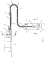
- reference 10 indicates a linear actuator, for example a pneumatic or hydraulic cylinder, connected to a member 11 to be controlled, by means of the push-pull control device comprising a flexible force transmission member according to the invention, indicated by reference 12.
- the rod 10' of the cylinder 10 is connected to the flexible member 12 of the control device, by means of a slider 13 which runs along a guide 14 capable of guiding the slider 13 and an end portion 12' of the same flexible force transmitting member 12 along the entire working stroke.
- the other end portion 12" of the flexible member 12 of the control device is connected to the controlled member 11 by means of a second slider 15 moving along a guide 16 which also extends for the entire length of the working stroke.
- the flexible member 12 can extend along any path defining a transmission line for transmitting movements, having rectilinear and/or curved portions, both on a plane or a surface and in the space, according to need.
- the flexible force transmitting member 12 of the control device substantially comprises two structurally independent, albeit functionally integrated, portions; more precisely, it comprises a first portion 17 designed to exert a pushing action or force, and a second portion 19 designed to exert a pulling action or force.
- the pushing portion of the flexible control device is provided by a plurality of cup-shaped articulated elements 17 having semi-spherical inner and outer coupling surfaces which are maintained in close contact with one another so as to allow any relative angular and/or rotational movement between one pushing element and another, both in the space and on any desired plane or surface.
- Each individual pushing element 17 is provided with a central hole 18 to allow the passage of a pull member 19 consisting for example of a metal wire, or of synthetic fibres or any other material, or combination of suitable materials, the ends of which are connected to the sliders 14 and 15, respectively, by means of a clamp 20.
- a pull member 19 consisting for example of a metal wire, or of synthetic fibres or any other material, or combination of suitable materials, the ends of which are connected to the sliders 14 and 15, respectively, by means of a clamp 20.
- the flexible control member 12, comprising the pushing elements 17 and the pull cable 19, is suitably tensioned by means of the clamps 20 to maintain the articulated pushing elements 17 in close contract with one another, inside a sliding and reaction sheath 21, the ends of which are suitably fastened to the guides 14 and 16, for example by means of a screw nut 22 or in any other suitable way.
- Figure 3 of the accompanying drawings shows an enlarged cross-sectional view of a push element 17 constituting part of the flexible control member 12 according to the invention.
- the push element 17 comprises a semi-spherical inner surface 23 having a preestablished radius of curvature and its centre on the longitudinal axis of the through hole 18 for passage of the pull cable 19; the cup-shaped element 17 also comprises a partially spherical outer surface 24 which meshes with a cylindrical surface 25 close to the front edge.
- each push element 17 Since the outer partially spherical surface 24 of each push element 17 is designed to be in contact in an articulated mode with the inner semi-spherical surface 23 of an adjacent push element 17, the partially spherical surface 24 also presents a radius of curvature corresponding to that of the inner semi-spherical surface 23, whose centre also lies on the longitudinal axis of the hole 18.
- the cylindrical surface 25 may be of any desired width, provided it is capable of allowing a wide angular and/or rotational movement or articulation between adjacent cup-shaped elements 17, and in any case sufficient to allow very sharp bends of the flexible control member, of up to 360° and over, thereby also creating possible spiral turns.
- the width of the cylindrical surface 25, in the direction of the axis of the hole 18, must be smaller than the maximum thickness of the semi-spherical wall of the member 17 in the region of the central hole 18.
- the maximum thickness of the wall can be 1 mm, with a cylindrical surface 25 having a length equal to or smaller than 0.8 mm.
- the hole 18 presents a conical shape converging towards the inner semi-spherical surface 23.
- the thickness of the wall of the cup-shaped element 17 is progressively reducing from the hole 18 towards the front edge of the surface 25. This has been made possible by manufacturing the cup-shaped elements 17 by coining, starting from a metal disk of appropriate diameter and thickness, provided with a central hole.
- a control device of the "push and pull" type to connect an actuator to a control member, which utilises a particular flexible member for transmitting the movement substantially comprising a pull cable which extends within a plurality of cup-shaped push elements articulated to one another, which carry out, in a correlated fashion, differentiated functions of pushing and pulling, making the system totally independent from any type and length of the transmission path, and from the required working stroke.
Landscapes
- Engineering & Computer Science (AREA)
- General Engineering & Computer Science (AREA)
- Health & Medical Sciences (AREA)
- Oral & Maxillofacial Surgery (AREA)
- Mechanical Engineering (AREA)
- Manipulator (AREA)
- Flexible Shafts (AREA)
Applications Claiming Priority (2)
| Application Number | Priority Date | Filing Date | Title |
|---|---|---|---|
| IT2000MI002644A IT1319360B1 (it) | 2000-12-06 | 2000-12-06 | Dispositivo flessibile di comando ad elementi articolati. |
| ITMI002644 | 2000-12-06 |
Publications (1)
| Publication Number | Publication Date |
|---|---|
| EP1213498A2 true EP1213498A2 (de) | 2002-06-12 |
Family
ID=11446192
Family Applications (1)
| Application Number | Title | Priority Date | Filing Date |
|---|---|---|---|
| EP01128729A Withdrawn EP1213498A2 (de) | 2000-12-06 | 2001-12-03 | Bowdenzug mit gelenkig verbundenen Elementen |
Country Status (4)
| Country | Link |
|---|---|
| US (1) | US20020066335A1 (de) |
| EP (1) | EP1213498A2 (de) |
| CA (1) | CA2364282A1 (de) |
| IT (1) | IT1319360B1 (de) |
Families Citing this family (1)
| Publication number | Priority date | Publication date | Assignee | Title |
|---|---|---|---|---|
| US8413542B2 (en) * | 2007-09-04 | 2013-04-09 | Dura Operating, Llc | Plastic core attachment for a push-pull cable assembly |
Citations (6)
| Publication number | Priority date | Publication date | Assignee | Title |
|---|---|---|---|---|
| FR685616A (fr) | 1929-11-26 | 1930-07-12 | Perfectionnements apportés aux transmissions avec chapelets de billes guidés dans des tubes | |
| GB2178505A (en) | 1985-07-29 | 1987-02-11 | Koito Mfg Co Ltd | Bowden apparatus for reciprocably moving a desired object |
| EP0301453A1 (de) | 1987-07-28 | 1989-02-01 | SWF Auto-Electric GmbH | Antriebsvorrichtung |
| DE4308181A1 (de) | 1993-03-15 | 1994-09-22 | Bayerische Motoren Werke Ag | Vorrichtung zum Öffnen und Schließen von verschwenkbaren Flügeln |
| DE19534643A1 (de) | 1995-03-23 | 1996-09-26 | Norbert Noetzold | Flexibles und leichtgängiges Kraftübertragungsmittel |
| EP1059462A1 (de) | 1999-06-08 | 2000-12-13 | Luciano Migliori | Flexible Druck-Zug Ubertragungsvorrichtung |
Family Cites Families (6)
| Publication number | Priority date | Publication date | Assignee | Title |
|---|---|---|---|---|
| US1291406A (en) * | 1915-02-08 | 1919-01-14 | Edwin D Chaplin | Electric donductor. |
| US1746719A (en) * | 1925-08-19 | 1930-02-11 | Steeldraulic Brake Corp | Flexible conduit |
| US1772453A (en) * | 1928-03-23 | 1930-08-12 | Midland Steel Prod Co | Flexible conduit |
| US1836822A (en) * | 1928-05-21 | 1931-12-15 | Midland Steel Prod Co | Unit for flexible conduits |
| US2850915A (en) * | 1957-03-15 | 1958-09-09 | American Chain & Cable Co | Push-pull cable |
| US3066404A (en) * | 1957-04-03 | 1962-12-04 | Ultradyne Inc | Method and apparatus for prestressing a remote power linear drive |
-
2000
- 2000-12-06 IT IT2000MI002644A patent/IT1319360B1/it active
-
2001
- 2001-12-03 EP EP01128729A patent/EP1213498A2/de not_active Withdrawn
- 2001-12-05 CA CA002364282A patent/CA2364282A1/en not_active Abandoned
- 2001-12-06 US US10/003,425 patent/US20020066335A1/en not_active Abandoned
Patent Citations (6)
| Publication number | Priority date | Publication date | Assignee | Title |
|---|---|---|---|---|
| FR685616A (fr) | 1929-11-26 | 1930-07-12 | Perfectionnements apportés aux transmissions avec chapelets de billes guidés dans des tubes | |
| GB2178505A (en) | 1985-07-29 | 1987-02-11 | Koito Mfg Co Ltd | Bowden apparatus for reciprocably moving a desired object |
| EP0301453A1 (de) | 1987-07-28 | 1989-02-01 | SWF Auto-Electric GmbH | Antriebsvorrichtung |
| DE4308181A1 (de) | 1993-03-15 | 1994-09-22 | Bayerische Motoren Werke Ag | Vorrichtung zum Öffnen und Schließen von verschwenkbaren Flügeln |
| DE19534643A1 (de) | 1995-03-23 | 1996-09-26 | Norbert Noetzold | Flexibles und leichtgängiges Kraftübertragungsmittel |
| EP1059462A1 (de) | 1999-06-08 | 2000-12-13 | Luciano Migliori | Flexible Druck-Zug Ubertragungsvorrichtung |
Also Published As
| Publication number | Publication date |
|---|---|
| ITMI20002644A1 (it) | 2002-06-06 |
| CA2364282A1 (en) | 2002-06-06 |
| IT1319360B1 (it) | 2003-10-10 |
| US20020066335A1 (en) | 2002-06-06 |
Similar Documents
| Publication | Publication Date | Title |
|---|---|---|
| EP2810745A1 (de) | Mehrgelenkige Armanordnung | |
| US8443692B2 (en) | Multi-linked device having a reinforcing member | |
| DE112012006256B4 (de) | Robotergelenkstruktur | |
| US20100263500A1 (en) | Manipulator tool and holding and/or expanding tool with at least one manipulator tool | |
| US4949585A (en) | Telescopic screw jack for the adjustment of an element such as a vehicle seat | |
| EP3998010B1 (de) | Selbstverriegelnde vorrichtung für ein endoskop | |
| EP3264968A1 (de) | Einteiliger biegehals für eine gelenkige ultraschallsonde | |
| US20100116079A1 (en) | Bidirectional tendon terminator | |
| WO2004096628A2 (en) | A method and apparatus for restraining cable curvature | |
| US20080196538A1 (en) | Conduit and control cable | |
| US20250282066A1 (en) | Snake-Arm Robot and Joint Therefor | |
| US3990321A (en) | Push-pull, cable-type actuator | |
| EP3326764A1 (de) | Manipulator | |
| EP1553226B1 (de) | Verfahren zur Herstellung eines Kabels sowie nach diesem Verfahren hergestelltes Kabel | |
| US20020066335A1 (en) | Flexible control device with articulated elements | |
| EP1059462A1 (de) | Flexible Druck-Zug Ubertragungsvorrichtung | |
| EP0511351B1 (de) | Kabel zur genauen übertragung von längsbewegung | |
| DE102008019786B3 (de) | Betätigungszug mit kunststoffummanteltem Innenzug | |
| EP2732936A1 (de) | Greifer mit entfernten Kabelantrieb | |
| JP2023018451A (ja) | 屈曲構造体 | |
| US10683639B2 (en) | Actuator | |
| US3135131A (en) | Push-pull cable construction | |
| KR100967437B1 (ko) | 고무호스용 강선편조장치 | |
| DE4308181A1 (de) | Vorrichtung zum Öffnen und Schließen von verschwenkbaren Flügeln | |
| DE4337096C1 (de) | Flexibler Aktuator |
Legal Events
| Date | Code | Title | Description |
|---|---|---|---|
| PUAI | Public reference made under article 153(3) epc to a published international application that has entered the european phase |
Free format text: ORIGINAL CODE: 0009012 |
|
| AK | Designated contracting states |
Kind code of ref document: A2 Designated state(s): AT BE CH CY DE DK ES FI FR GB GR IE IT LI LU MC NL PT SE TR |
|
| AX | Request for extension of the european patent |
Free format text: AL;LT;LV;MK;RO;SI |
|
| STAA | Information on the status of an ep patent application or granted ep patent |
Free format text: STATUS: THE APPLICATION HAS BEEN WITHDRAWN |
|
| 18W | Application withdrawn |
Effective date: 20030919 |