EP1213817A2 - Procédé pour la détermination de la nécessité de changer un composant et dispositif pour mettre en oeuvre le procédé - Google Patents
Procédé pour la détermination de la nécessité de changer un composant et dispositif pour mettre en oeuvre le procédé Download PDFInfo
- Publication number
- EP1213817A2 EP1213817A2 EP01250425A EP01250425A EP1213817A2 EP 1213817 A2 EP1213817 A2 EP 1213817A2 EP 01250425 A EP01250425 A EP 01250425A EP 01250425 A EP01250425 A EP 01250425A EP 1213817 A2 EP1213817 A2 EP 1213817A2
- Authority
- EP
- European Patent Office
- Prior art keywords
- battery
- time
- component
- measurement
- current
- Prior art date
- Legal status (The legal status is an assumption and is not a legal conclusion. Google has not performed a legal analysis and makes no representation as to the accuracy of the status listed.)
- Granted
Links
Images


Classifications
-
- H—ELECTRICITY
- H02—GENERATION; CONVERSION OR DISTRIBUTION OF ELECTRIC POWER
- H02J—ELECTRIC POWER NETWORKS; CIRCUIT ARRANGEMENTS OR SYSTEMS FOR SUPPLYING OR DISTRIBUTING ELECTRIC POWER; SYSTEMS FOR STORING ELECTRIC ENERGY
- H02J7/00—Circuit arrangements for charging or discharging batteries or for supplying loads from batteries
- H02J7/80—Circuit arrangements for charging or discharging batteries or for supplying loads from batteries including monitoring or indicating arrangements
- H02J7/82—Control of state of charge [SOC]
-
- H—ELECTRICITY
- H02—GENERATION; CONVERSION OR DISTRIBUTION OF ELECTRIC POWER
- H02J—ELECTRIC POWER NETWORKS; CIRCUIT ARRANGEMENTS OR SYSTEMS FOR SUPPLYING OR DISTRIBUTING ELECTRIC POWER; SYSTEMS FOR STORING ELECTRIC ENERGY
- H02J7/00—Circuit arrangements for charging or discharging batteries or for supplying loads from batteries
- H02J7/80—Circuit arrangements for charging or discharging batteries or for supplying loads from batteries including monitoring or indicating arrangements
- H02J7/84—Control of state of health [SOH]
Definitions
- the invention relates to a method for determining a need for Replacement of a component according to the preamble of claim 1 specified type and an arrangement for performing the method, according to the kind specified in the preamble of claim 8
- the arrangement can be a postal security module, which in particular for use in a franking machine or mail processing machine or computer with post processing function is suitable and which allows a battery replacement.
- Mail processing systems are today modularly built around at Access product variants to as many existing modules as possible can. This procedure saves the constant new development of Functionalities for use in new variants of systems. Modules are designed so that they have at least one function can perform, which should be used in different variants. The low cost is another advantage of modular systems and easy exchange of modules if they are used up or fail. The display of consumption and also the warning of future ones Failure of modules are mechanisms that the timely Enable switching from such modules and today to the scope of service modern mail processing systems. For this service functionality different techniques are used.
- the defined threshold is often dependent on various parameters in operation (e.g. temperature, humidity). These parameters can significantly shift the actual threshold. This can have the consequence that under certain operating conditions the consumption can be higher or lower or the failure can occur sooner or later. In all of these cases, different financial damages for the user or owner of the system can occur, which must be prevented.
- Direct measurements must be set up individually depending on the component or module and can quickly increase the unit costs if several components or modules are to be monitored. Furthermore, some components or modules are limited in their function by direct measuring techniques. For example, the capacity measurement of a battery can significantly reduce the service life if the normal current consumption is lower than that required for the measurement.
- a safety module can assume various states in its life cycle, but these are only displayed when system voltage is present.
- the battery of the security module would quickly run out.
- the battery life should be appropriate to the life cycle and as long as possible. If the franking machine is switched off, power interruptions or system power failures, the postal register data, cryptographic keys and other sensitive data must be retained and the real-time clock must also continue to run. In addition, there are permanent monitoring functions that must continue without interruption. This increases the need for available battery power, with the result that the life of the battery is reduced.
- the invention has for its object a method for determining to develop a need to replace a component, the Measurement of a parameter is avoided when measuring it on the consumption or the life of the component an unfavorable Influences.
- the security against failure especially of Components with battery-supported data storage must be increased and at the same time make optimal use of the battery life.
- the method is to be used, for example, in franking machines, for the special security requirements regarding the postal register data apply with the monetary billing data.
- the object is with the features of claim 1 for a method and solved with the features of claim 8 for an arrangement.
- an arrangement consisting of a timer for delivering a time parameter, at least one sensor for recording measured values of a parameter, at least one component, its failure is influenced by this parameter, a microprocessor with the Sensor and the timer is connected, a memory for this Parameter contains specific values, a memory that contains a count stores, which determines the failure of the component and a program memory, which is connected to the microprocessor, the Microprocessor performs a function in the program memory, which depends on the measured value of the parameter, the time parameter and modified the latter so that this one for the component approaching the specific failure threshold and a warning when it is reached generated.
- the module processor of a Safety module monitors the battery with regard to its service life, hardware-related Billing unit and memory relating to the billing function or data as well as other assemblies with regard to further Functions. The focus is on the availability of the system and an appropriate response to it. Using the example of battery monitoring, the invention is explained in more detail. The requirement to Battery replacement is based on an evaluation of a measurement of the Ambient temperature of the battery and a time measurement determined. A the capacity of the battery is a direct current / voltage measurement can therefore be omitted.
- the evaluation of a measurement of the ambient temperature takes place in relation to the self-discharge current of the battery. Due to an uninterrupted real-time measurement, one can Microprocessor time intervals is determined, being between one Transport time interval as well as operating and rest time intervals of the Device is distinguished.
- the measurement and evaluation of the Ambient temperature in relation to the self-discharge current of the battery takes place in the operating time interval, i.e. after the transportation time interval or after a rest period of the device.
- As part of the evaluation become electricity / time products for the aforementioned intervals in the operating time interval formed, using empirically determined currents in the calculation received in the transport time interval or in the rest time interval of the Device flow and reduce the battery capacity.
- FIG. 1 shows the temperature dependence of the capacity of a lithium battery (from Sunshine).
- I LB 10 mA
- their capacitance fluctuates by approximately one fifth (0.3 Ah) in the permissible operating temperature range from + 5 ° C to + 40 ° C.
- I LB 0.5 mA
- the capacity fluctuation is up to an order of magnitude less.
- a maximum load current of I LT 50 ⁇ A flows, ie it is an order of magnitude above the current of the battery self-discharge at 25 ° C.
- the load current is caused by components that can sometimes have opposite temperature behavior.
- a real-time clock is integrated in the module processor of the security module, which continues to run during the transport time.
- the initial capacity is C t0 at time to and the capacity loss at the end of the transport time at time t 1 is C t1 .
- the real-time clock is queried at the time to and the date and time are stored together with the initial capacity C t0 .
- a later formed current / time product C t1 allows the capacity reduction to be determined approximately under worst case conditions without having to carry out a direct capacity measurement.
- there is the aforementioned capacity reduction due to the load current of I LT 0.05 mA.
- the positive battery of the second battery 140 is connected to one of the two inputs of the voltage changeover switch 180 via the line 189.
- a series connection of Schottky diodes 183, 182 leads to the output of the voltage switch 180.
- a switch S At the center tap of the series connection, on the one hand there is a switch S, a measuring resistor Rm to ground, and on the other hand a line 187 leads to a microprocessor via an analog / digital converter ADC (Not shown). The latter can open the switch S again when the measurement is finished.
- the loss voltage U V drops across the diodes or switches if electronically controllable switches are used instead of the diodes.
- the typical discharge curves, for example at 25 ° C, for lithium batteries show an almost ideal course in the voltage / time diagram until shortly before the end of the service life, where the discharge curve kinks sharply.
- this linearity allows an evaluation of whether the voltage is present before a non-linear region begins in which the discharge curve kinks sharply.
- a reduction in capacity due to a current / time product, which is due to the direct voltage measurement is, however, much greater than a reduction in capacity due to a current / time product, which was determined empirically for the indirect capacity measurement.
- the reduction in capacity can be determined indirectly and a need to replace the battery can be determined.
- time intervals can be determined by a microprocessor which contribute to a different extent to the reduction in capacity, a distinction being made between a transport time interval and operating and idle time intervals.
- the operating and rest periods alternate.
- the current / time products are calculated in the operating time intervals, in particular for the temperature-dependent battery discharge current that flows during the operating time intervals of the device, as well as for the temperature-dependent battery discharge current and a load current I LT flowing in the idle time intervals .
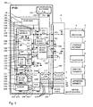
- FIG. 3 shows a measuring circuit for indirect determination of a value.
- a sensor 15 preferably a temperature sensor, is connected to a microprocessor 120 via a line 151 and an analog / digital converter ADC 123.
- the latter can be the module processor of the PSD 100 security module, which internally has an ADC and a real-time clock RTC 124.
- the microprocessor 120 is connected to a flash ROM 128 via address and data lines and to an input / output unit I / O 125.
- a first battery 134 (not shown) is located with the security module directly in a security area of a device, for example a franking machine, which is not accessible to the user.
- the first battery 134 can be firmly soldered onto the security module and it can be relatively small and cheap.
- the storage time with exclusive supply by this battery can be of the order of a few years, however the storage time of this battery must be ⁇ 12 years.
- the lifespan of the battery can reach a maximum of 0.1 mega hours and practically 0.015 mega hours because of its self-discharge, since the RTC 124 real-time clock must be constantly supplied. The latter corresponds to at least 12 years.
- This battery is a 3 V lithium battery and can already be connected to the safety module / component requiring battery voltage during the running production process in order to enable the storage of information (initialization).
- a sensor In a mail processing system there is at least one sensor and a parameter or suitable characteristic of the battery used, which are stored in a suitable form.
- This sensor can be a temperature sensor, for example.
- the mail processing system contains at least one component or module that is threatened with consumption or failure.
- This component can be a battery or is any component or module.
- the temperature now has a significant influence on the capacity of the battery and can change its consumption significantly or cause the failure of entire modules that are supplied by the battery.
- batteries are used to supply security modules that secure mail registers or even cross-machine secrets. Since the lifespan of a mail processing system generally exceeds that of the battery, a suitable warning for an upcoming replacement or an energy refill is required. Precise determination of the capacity by direct measurement is expensive and also reduces the capacity.
- a microprocessor can determine a capacity with the aid of a count, the temperature recorded by the sensor and the characteristic curve corresponding to this battery. This must not reach a predefined threshold without the system issuing a warning. It is irrelevant whether the characteristic curve can be stored in a table or calculated differently. The more frequently this determination is made and the more parameters are included in the determination, the more precise the capacity determined by this microprocessor becomes.
- the measurement results from the temperature sensor can be used simultaneously for other components or modules (ink or thermal print head). During operation from time t 1 , the safety module is supplied with a system voltage. This ends the transport time interval t 1 - t 0 .
- the room temperature ⁇ 1 is measured at time t 1 in order to decide whether the temperature is in the permissible temperature range for the operation of the module. Then the empirically determined current / time product C t1 for the idle time and / or for the transport time is formed for the indirect capacity measurement according to equation (1) and evaluated with regard to the reduction in the battery capacity.
- the ambient temperature will usually be within the permissible operating temperature range of + 5 ° C to + 40 ° C
- the safety module can heat up to approx. 60 ° C during operation.
- the security module still has room temperature ⁇ 1 .
- the temperature of the safety module increases inversely to the exponential curve.
- the load current for example for the real-time clock, is carried by the power supply and does not cause a reduction in capacity. This means that only the battery self-discharge current flows and there is a remaining capacity:
- C rest C t0 - ⁇ C t1 + C t2 + C t3 ⁇
- C rest C t0 - ⁇ C t1 + C t2 + C t3 ⁇
- a max. Load current of I LT 0.05 mA.
- the ambient temperature will usually be within the permissible operating temperature range of + 5 ° C to + 40 ° C. Without system voltage, however, no temperature measurement can be carried out, so a temperature estimate is required.
- the battery of the safety module will quickly reach the ambient temperature after switching off, which must not exceed + 44 ° C. It should also be assumed that the ambient temperature continues to cool at night and does not exceed + 20 ° C in the morning.
- the self-discharge current is only approx. 1 ⁇ A.
- the capacity decreases further due to battery self-discharge, but to a lesser extent.
- the difference between a current / time product C t1 determined for a transport time interval and a residual capacity x * C t0 is determined, which corresponds to a predetermined proportion of x% of the original battery capacity C t0 .
- the battery only needs to be replaced when the aforementioned difference is no longer smaller than the sum of all current / time products ⁇ C tn that are determined during the operating intervals for the operating and idle time intervals of the device.
- the module processor 120 can enter into a communication connection with a remote data center (not shown) via the system bus and, for example, a modem (not shown).
- a first and a second non-volatile memory in the postal security module PSD 100 are designed accordingly.
- the billing is carried out by the user-specific circuit ASIC 150 of the postal security module PSD 100.
- the ASIC 150 contains at least one hardware accounting unit for the calculation of the postal data to be stored.
- the ASIC 150 is controlled by a programmable array logic (PAL) 160. Access logic for the ASIC 150 is accommodated in the logic PAL 160.
- PAL programmable array logic
- An address and control bus 117, 115 from the main board of the meter 1 is connected to corresponding pins of the logic PAL 160 and the PAL 160 generates at least one control signal for the ASIC 150 and a control signal 119 for the program memory FLASH 128.
- the module processor 120 processes a program that is stored in the FLASH 128.
- the module processor 120 and the other modules, such as FLASH 128, ASIC 150 and PAL 160, are connected to one another via an internal system bus which contains lines 110, 111, 126, 119 for data, address and control signals.
- a KS32C41000 RISK MICROPROCESSOR from Samsung is particularly suitable as module processor 120.
- the latter internally has a processing unit CPU 121, a real-time clock RTC 122, an A / D converter ADC 123 and an input / output unit 125.
- the module processor 120 of the security module 100 is connected to a FLASH 128 and to the ASIC 150 via an internal data bus 126.
- the FLASH 128 serves as program memory and is supplied with system voltage Us +. It is, for example, a 128 Kbyte FLASH memory of the type AM29F010-45EC.
- the module processor 120 of the security module 100 supplies the addresses 0 to 15 to the corresponding address inputs of the FLASH 128 and a static working memory SRAMs 122 via an internal address bus 111.
- the ASIC 150 of the security module 100 is also available via the contact group 101, 102 of the interface with the data bus 118 the address bus 117 and the control bus 115 of the main board of the meter 2 in communication connection.
- the RESET unit 130 is connected via line 131 to pin 3 of module processor 120 and to a pin of ASIC's 150.
- the module processor 120 and the ASIC 150 are reset when the system voltage drops by a reset generation in the RESET unit 130.
- the first battery 134 feeds the real-time clock 122 with the date / time registers and the static working memory SRAM 124, which contains safety-relevant data.
- the negative pole 104 of the first battery 134 is grounded and a pin P23 of the contact group 101.
- the positive pole 103 of the first battery 134 is connected via the line 193 to one input of the voltage changeover switch 180 and the pin P25 of the contact group 101, which carries the system voltage, is connected via a line 191 to the other input of the voltage changeover switch 180. If the system voltage is designed for a higher nominal voltage than the first battery 134, then Schottky diodes are sufficient for decoupling, otherwise switches controlled by voltage switches 180 must be used.
- the DS 1314 circuit from Dallas Semiconductor or a commercially available circuit type ADM 8693ARN are suitable as voltage switches 180.
- the first battery 134 is, for example, a lithium battery of the CR 1/2 AA CD type from Varta. Their nominal capacity C t0 is given as 950 mAh.
- the second non-volatile memory NVRAM is based on a second technology (SHADOW-RAM).
- This second technology preferably comprises a RAM and an EEPROM, the latter automatically taking over the data content in the event of a system power failure.
- the NVRAM 116 of the second technology is connected to the corresponding address and data inputs of the user-specific circuit ASIC 150 via an internal address and data bus 112, 113.
- the circuit of the voltage monitoring unit 12 is, for example dimensioned so that any drop in battery voltage on the Line 136 below the specified 2.6 V threshold to respond the circuit 12 leads. Simultaneously with the indication of undervoltage the battery, the circuit 12 changes to a self-holding state, in to which it remains even when the voltage is increased afterwards. It delivers also a status signal 164. The next time the module is switched on the module processor 120 can determine the state of the circuit (status signal) query and / or about the evaluation of the content of the deleted The memory suggests that the battery voltage in the meantime has fallen below a certain value. The module processor 120 may reset monitoring circuit 12, i.e. "sharp" do. The latter responds to a control signal on line 135.
- the line 136 at the input of the voltage monitoring unit 12 also supplies a detection unit 13 with operating or battery voltage.
- the detection unit 13 is connected to a conductor loop 192, 194, which is incorporated in the housing of the security module and is potted with potting compound (for example synthetic resin). An attack on the housing (e.g. drilling) can thus be detected.
- the state of the detection unit 13 is queried by the processor 120 via the line 139 or the detection unit 13 is triggered or set by the module processor 120 via the line 137. After setting, a static check for connection is carried out. For this purpose, a ground potential is queried via a line 195, which is present at the connection P4 of the interface 8 of the postal security module PSD 100 and can only be queried if the security module 100 is properly inserted.
- the ground potential of the negative pole 104 of the battery 134 of the postal security module PSD 100 is connected to the connection P23 of the interface 8 and can thus be queried by the detection unit 13 at the connection P4 of the interface via the line 192.
- Lines are connected to pins 6 and 7 of module processor 120 via detection unit 13, which only form a conductor loop 17 when a security module 100 is plugged in, for example on the main circuit board of meter 1.
- the module processor 120 applies changing signal levels at very irregular intervals to the pins 6, 7 and loops it back over the loop.
- the module processor 120 is equipped with the input / output unit 125, the connections of which pins 8, 9 are used to output at least one signal for signaling the state of the security module 100.
- I / O ports of the input / output unit 125 to which module-internal signaling means are connected for example colored light emitting diodes LED's 107, 108, are located at pins 8 and 9. These signal the module status when a security module 100 is plugged onto the main board of meter 1 through an opening 109 in the meter housing.
- the safety modules can assume various states in their life cycle. For example, the battery status must be detected and whether the security module contains valid cryptographic keys. It is also important to differentiate whether the safety module is working or defective.
- a sensor 15 is connected to the microprocessor via the analog / digital converter 123.
- the P25 of the contact group 101 which carries the system voltage, supplies the supply voltage for the sensor 15.
- the analog / digital converter 123 supplies the microprocessor with a digitized measured value for evaluating the present temperature.
- the microprocessor is connected via an input / output means 125 either directly to a signaling means 107, 108 for the states of the security module or indirectly to a signaling means of the meter (beeper) or to its display unit 4.
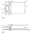
- FIG. 6 shows the mechanical structure of the security module in top view.
- the security module is designed as a multi-chip module, i.e. in a first part, several functional units are one Printed circuit board 106.
- the potting compound 105 surrounds cuboid the first part of the circuit board 106, while a second part of the Printed circuit board 106 for the first battery 134 remains free of sealing compound.
- the Circuit board 106 has an opening 109 for the first battery 134 and Solder points or battery contact terminals 103 and 104 for connection the pole of the battery 134, preferably below the circuit board 106.
- To connect the PSD 100 postal security module to the The main circuit board of meter 2 is the contact group 101 (dashed drawn) below the circuit board 106 (conductor track side) of the Security module 100 arranged.
- FIG. 7 is a side view of the postal security module shown. If the security module is connected to the interface 8 Main board plugged in, then it can be inside the meter housing be arranged so that the signal means 107, 108 near a Opening 20 (Fig.3) is or protrudes into this.
- the meter case is thus advantageously constructed so that the user can view the status of the Security module can still see from the outside (Fig. 3).
- Both LEDs are housed in a common component housing (Bicolor light emitting diode), which is why the dimensions or the diameter of the Opening can remain relatively small and of the order of magnitude Signal means is. In principle, three different colors can be displayed (red, green, orange), according to which the light emitting diodes LED individually or can be controlled simultaneously.
- the two LEDs 107 and 108 of the signaling means may alternatively be placed in one place, so that the latter can only be observed by a service technician or the two output signals of the I / O ports on pins 8, 9 of the module processor 120 become a display unit via the processor of the main board 5 transmitted.
- the module processor takes monitoring and Signaling of the module status before and is only in the operating time interval activated, i.e. when supplying the safety module with system voltage, which has a gentle effect on the battery.
- the module processor monitors the hardware accounting unit, the memories and the first battery 134 and further assemblies in the security area. there stands the reliable detection of malfunctions or failures or Exhaustion and a suitable reaction to it in the foreground.
- FIG. 7 shows a flow chart for the method according to the invention.
- the Module processor 120 When determining the need to replace the battery, the Module processor 120 a number of steps.
- a query step 201 is reached and the count n of a loop counter is evaluated.
- Step 203 is then reached in order to query the count of the real-time counter at time t 1 .
- the room temperature ⁇ 1 is measured at time t 1 .
- a sub-step (not shown) can be used to decide whether the temperature is within the permissible temperature range for the operation of the module.
- step 208 a branch to a step 208 to the count of the real time counter at the time t n query and at the time t n measured room temperature ⁇ n for the calculation of the associated current / time product C tn to be used according to the equation (4).
- step 210 the current / time products are added, as can be seen from equations (3) and (10). A count is modified so that it approaches a failure threshold specific to the battery, at which a warning is issued by the device before the end of consumption or end of life of the battery is reached.
- query step 211 the fulfillment of inequality (11) is queried.
- step 206 in which the switch-off is queried again.
- a branch is made from step 200 to query step 201 and a query is made as to whether the predetermined counter reading n 2 2 has been reached or exceeded in order to branch to step 209.
- a specific current / time product C tn for the rest time interval is formed in accordance with equation (7).
- the process then branches to step 210 and the sum of all current / time products ⁇ C tn is determined in order to then evaluate the query to be made in accordance with equation (11) again.
- the current / time product C t1 is formed for the rest period and / or for the transport time and evaluated with regard to the reduction in the battery capacity for a warning to be issued.
- measurement can be based on a parameter based on consumption or the service life of another component has an unfavorable influence takes, by measuring at least two representative parameters are replaced, the changes to the current state of the component allow to calculate. Again, a count is modified so that it approaching a failure threshold specific to the component and that a warning is issued by the device before the end of consumption or end of life of the component is reached.
- the invention can advantageous for the indirect measurement of parameters of components can be used in a security module or in its in the immediate vicinity
- a security module is preferably for use in postal Devices determined, especially for use in a franking machine.
- the security module can also have a different design, which allows it to be, for example, on the motherboard of a Personal computer can be plugged in as a PC franking machine controls conventional printer.
Landscapes
- Engineering & Computer Science (AREA)
- Power Engineering (AREA)
- Charge And Discharge Circuits For Batteries Or The Like (AREA)
- Secondary Cells (AREA)
- Testing Electric Properties And Detecting Electric Faults (AREA)
Applications Claiming Priority (2)
| Application Number | Priority Date | Filing Date | Title |
|---|---|---|---|
| DE10061665 | 2000-12-11 | ||
| DE10061665A DE10061665A1 (de) | 2000-12-11 | 2000-12-11 | Verfahren zur Ermittlung eines Erfordernis zum Austausch eines Bauteils und Anordnung zur Durchführung des Verfahrens |
Publications (3)
| Publication Number | Publication Date |
|---|---|
| EP1213817A2 true EP1213817A2 (fr) | 2002-06-12 |
| EP1213817A3 EP1213817A3 (fr) | 2005-07-13 |
| EP1213817B1 EP1213817B1 (fr) | 2008-09-10 |
Family
ID=7666701
Family Applications (1)
| Application Number | Title | Priority Date | Filing Date |
|---|---|---|---|
| EP01250425A Expired - Lifetime EP1213817B1 (fr) | 2000-12-11 | 2001-12-03 | Procédé pour la détermination de la nécessité de changer un composant |
Country Status (3)
| Country | Link |
|---|---|
| US (1) | US6512376B2 (fr) |
| EP (1) | EP1213817B1 (fr) |
| DE (2) | DE10061665A1 (fr) |
Families Citing this family (5)
| Publication number | Priority date | Publication date | Assignee | Title |
|---|---|---|---|---|
| DE10228806B3 (de) * | 2002-06-27 | 2004-03-04 | Fraunhofer-Gesellschaft zur Förderung der angewandten Forschung e.V. | Einrichtung und Verfahren zum Bestimmen eines Ladezustands einer Batterie |
| JP2004251972A (ja) * | 2003-02-18 | 2004-09-09 | Fuji Photo Film Co Ltd | 属性情報管理システム |
| US7380233B2 (en) * | 2005-08-31 | 2008-05-27 | International Business Machines Corporation | Method of facilitating integrated circuit design using manufactured property values |
| US7212934B1 (en) | 2006-03-06 | 2007-05-01 | United States Of America As Represented By The Administrator Of The National Aeronautics And Space Administration | String resistance detector |
| DE202015106539U1 (de) | 2015-12-01 | 2017-03-06 | Rp-Technik Gmbh | Zustandsindikator und Kommunikationssystem zur Kontrolle von Akkumulatoren |
Family Cites Families (28)
| Publication number | Priority date | Publication date | Assignee | Title |
|---|---|---|---|---|
| US3962539A (en) | 1975-02-24 | 1976-06-08 | International Business Machines Corporation | Product block cipher system for data security |
| US4200770A (en) | 1977-09-06 | 1980-04-29 | Stanford University | Cryptographic apparatus and method |
| US4405829A (en) | 1977-12-14 | 1983-09-20 | Massachusetts Institute Of Technology | Cryptographic communications system and method |
| US4689478A (en) | 1984-12-24 | 1987-08-25 | Ncr Corporation | System for handling transactions including a portable personal terminal |
| US4812965A (en) | 1985-08-06 | 1989-03-14 | Pitney Bowes Inc. | Remote postage meter insepction system |
| US4804957A (en) | 1985-11-27 | 1989-02-14 | Triad Communications, Inc. | Utility meter and submetering system |
| DE3703387A1 (de) | 1986-02-06 | 1987-08-27 | Gossen Gmbh | Verfahren und vorrichtung zum automatischen erfassen und/oder verteilen und/oder abrechnen und/oder anzeigen von energieverbrauchsdaten bzw. -kosten |
| DE3723530A1 (de) | 1987-07-16 | 1989-01-26 | Martin Dipl Ing Kahmann | Anzeigeeinheit fuer verbrauchszaehl- und tarifgeraete |
| DE3734946A1 (de) | 1987-10-15 | 1989-05-03 | Siemens Ag | Hoergeraet mit moeglichkeit zum telefonieren |
| US5027397A (en) | 1989-09-12 | 1991-06-25 | International Business Machines Corporation | Data protection by detection of intrusion into electronic assemblies |
| US5243654A (en) | 1991-03-18 | 1993-09-07 | Pitney Bowes Inc. | Metering system with remotely resettable time lockout |
| US5231668A (en) | 1991-07-26 | 1993-07-27 | The United States Of America, As Represented By The Secretary Of Commerce | Digital signature algorithm |
| DE4243092C2 (de) | 1992-12-18 | 1996-03-14 | Ludwig Kreuzpaintner | Stromverteilersystem |
| ATE229210T1 (de) | 1993-03-22 | 2002-12-15 | Kundo Systemtechnik Gmbh | Anlage zur zentralen erfassung von energieverbrauchskosten |
| DE19549376A1 (de) | 1995-03-07 | 1996-09-26 | Francotyp Postalia Gmbh | Anordnung zur Ermittlung einer Farbbandrestmenge für Thermotransferdruckverfahren |
| JP3136981B2 (ja) * | 1996-02-07 | 2001-02-19 | 松下電器産業株式会社 | 蓄電池の寿命予告方法および寿命予告装置 |
| JP3539822B2 (ja) * | 1996-03-29 | 2004-07-07 | 新電元工業株式会社 | 無停電電源装置 |
| US5953426A (en) | 1997-02-11 | 1999-09-14 | Francotyp-Postalia Ag & Co. | Method and arrangement for generating and checking a security imprint |
| SK69898A3 (en) | 1997-06-13 | 2000-05-16 | Bernina Electronic Ag | Method and device for measuring a consumption |
| DE19748954A1 (de) | 1997-10-29 | 1999-05-06 | Francotyp Postalia Gmbh | Verfahren für eine digital druckende Frankiermaschine zur Erzeugung und Überprüfung eines Sicherheitsabdruckes |
| DE19754675A1 (de) | 1997-12-10 | 1999-07-01 | Klaus Dipl Ing Weber | Einrichtung zum kundenseitigen Erfassen und Abrechnen des Haushaltsverbrauchs von Versorgungsgütern |
| JPH11183575A (ja) * | 1997-12-17 | 1999-07-09 | Fuji Electric Co Ltd | フィールド機器の電池寿命予測方法 |
| JP2000184619A (ja) * | 1998-12-18 | 2000-06-30 | Matsushita Electric Ind Co Ltd | 無停電電源装置 |
| DE19912780A1 (de) | 1999-03-12 | 2000-09-14 | Francotyp Postalia Gmbh | Anordnung für ein Sicherheitsmodul |
| DE50015220D1 (de) | 1999-03-12 | 2008-08-07 | Francotyp Postalia Gmbh | Anordnung zum Schutz eines Sicherheitsmoduls |
| DE29905219U1 (de) | 1999-03-12 | 1999-06-17 | Francotyp-Postalia AG & Co., 16547 Birkenwerder | Sicherheitsmodul mit Statussignalisierung |
| DE19912781A1 (de) | 1999-03-12 | 2000-11-23 | Francotyp Postalia Gmbh | Verfahren zum Schutz eines Sicherheitsmoduls und Anordnung zur Durchführung des Verfahrens |
| DE19958940A1 (de) | 1999-12-08 | 2001-06-13 | Jobst Gmbh | Maßbrett für die Beinmessung |
-
2000
- 2000-12-11 DE DE10061665A patent/DE10061665A1/de not_active Withdrawn
-
2001
- 2001-12-03 DE DE50114302T patent/DE50114302D1/de not_active Expired - Lifetime
- 2001-12-03 EP EP01250425A patent/EP1213817B1/fr not_active Expired - Lifetime
- 2001-12-03 US US10/004,898 patent/US6512376B2/en not_active Expired - Fee Related
Also Published As
| Publication number | Publication date |
|---|---|
| US20020097054A1 (en) | 2002-07-25 |
| DE50114302D1 (de) | 2008-10-23 |
| EP1213817B1 (fr) | 2008-09-10 |
| DE10061665A1 (de) | 2002-06-20 |
| US6512376B2 (en) | 2003-01-28 |
| EP1213817A3 (fr) | 2005-07-13 |
Similar Documents
| Publication | Publication Date | Title |
|---|---|---|
| DE69231869T2 (de) | Verfahren und Gerät zur Prüfung elektronischer Elektrizitätszähler | |
| EP0433280B1 (fr) | Montage pour dispositifs d'impression, destine au controle de reservoirs contenant du fluide d'impression | |
| EP0660269B1 (fr) | Procédé pour améliorer la sécurité de machines à affrauchir | |
| EP1035517B1 (fr) | Procédé de protection d'un module de sécurité et ensemble pour mettre en oeuvre ledit procédé | |
| DE19958941B4 (de) | Verfahren zum Schutz eines Gerätes vor einem Betreiben mit unzulässigem Verbrauchsmaterial | |
| CH677464A5 (fr) | ||
| CH650602A5 (de) | Elektronische frankiermaschine. | |
| EP1035516B1 (fr) | Système pour un module de sécurité | |
| DE69014516T2 (de) | System zur Abgabe von Verbrauchsmitteln. | |
| DE3382623T2 (de) | Elektronische frankiermaschine mit ruecksetzschaltkreis. | |
| DE2463404C2 (de) | Frankiereinrichtung mit einer Frankiermaschine | |
| EP1209631B1 (fr) | Dispositif d'alimentation électrique d'un secteur de securité d'un appareil | |
| EP1213817B1 (fr) | Procédé pour la détermination de la nécessité de changer un composant | |
| EP1035513B1 (fr) | Module de sécurité avec signalisation de l'état | |
| DE20112350U1 (de) | Anordnung zum Schutz eines Sicherheitsmoduls | |
| DE19928057A1 (de) | Sicherheitsmodul und Verfahren zur Sicherung der Postregister vor Manipulation | |
| EP0560714B1 (fr) | Machine d'affranchissement | |
| EP1031041B1 (fr) | Dispositif permettant de controler un moteur electrique | |
| DE19802462A1 (de) | Einrichtung zur zweifelsfreien automatischen Identifizierung von Sensoren an chemischen Analysengeräten | |
| DE19928061C2 (de) | Sicherheitsmodul zur Überwachung der Systemsicherheit und Verfahren | |
| DE69224810T2 (de) | Frankiermaschine | |
| DE102017203683B4 (de) | Zählsensor mit korrekturfunktion | |
| DE102013017580B4 (de) | Elektronischer produktograf für fahrgeschäfte | |
| EP1389729A1 (fr) | Procédé et dispositifs pour la surveillance de la quantité de remplissage | |
| DE3630947C2 (fr) |
Legal Events
| Date | Code | Title | Description |
|---|---|---|---|
| PUAI | Public reference made under article 153(3) epc to a published international application that has entered the european phase |
Free format text: ORIGINAL CODE: 0009012 |
|
| AK | Designated contracting states |
Kind code of ref document: A2 Designated state(s): AT BE CH CY DE DK ES FI FR GB GR IE IT LI LU MC NL PT SE TR |
|
| AX | Request for extension of the european patent |
Free format text: AL;LT;LV;MK;RO;SI |
|
| PUAL | Search report despatched |
Free format text: ORIGINAL CODE: 0009013 |
|
| AK | Designated contracting states |
Kind code of ref document: A3 Designated state(s): AT BE CH CY DE DK ES FI FR GB GR IE IT LI LU MC NL PT SE TR |
|
| AX | Request for extension of the european patent |
Extension state: AL LT LV MK RO SI |
|
| 17P | Request for examination filed |
Effective date: 20050720 |
|
| RAP1 | Party data changed (applicant data changed or rights of an application transferred) |
Owner name: FRANCOTYP-POSTALIA GMBH |
|
| AKX | Designation fees paid |
Designated state(s): CH DE FR GB IT LI |
|
| 17Q | First examination report despatched |
Effective date: 20060628 |
|
| GRAP | Despatch of communication of intention to grant a patent |
Free format text: ORIGINAL CODE: EPIDOSNIGR1 |
|
| RTI1 | Title (correction) |
Free format text: METHOD FOR THE DETERMINATION OF A NEED TO EXCHANGE A COMPONENT |
|
| GRAS | Grant fee paid |
Free format text: ORIGINAL CODE: EPIDOSNIGR3 |
|
| GRAA | (expected) grant |
Free format text: ORIGINAL CODE: 0009210 |
|
| AK | Designated contracting states |
Kind code of ref document: B1 Designated state(s): CH DE FR GB IT LI |
|
| REG | Reference to a national code |
Ref country code: GB Ref legal event code: FG4D Free format text: NOT ENGLISH |
|
| REG | Reference to a national code |
Ref country code: CH Ref legal event code: EP |
|
| REF | Corresponds to: |
Ref document number: 50114302 Country of ref document: DE Date of ref document: 20081023 Kind code of ref document: P |
|
| PLBE | No opposition filed within time limit |
Free format text: ORIGINAL CODE: 0009261 |
|
| STAA | Information on the status of an ep patent application or granted ep patent |
Free format text: STATUS: NO OPPOSITION FILED WITHIN TIME LIMIT |
|
| 26N | No opposition filed |
Effective date: 20090611 |
|
| PGFP | Annual fee paid to national office [announced via postgrant information from national office to epo] |
Ref country code: GB Payment date: 20101221 Year of fee payment: 10 |
|
| PGFP | Annual fee paid to national office [announced via postgrant information from national office to epo] |
Ref country code: DE Payment date: 20101019 Year of fee payment: 10 |
|
| PGFP | Annual fee paid to national office [announced via postgrant information from national office to epo] |
Ref country code: CH Payment date: 20111227 Year of fee payment: 11 Ref country code: FR Payment date: 20120105 Year of fee payment: 11 |
|
| PGFP | Annual fee paid to national office [announced via postgrant information from national office to epo] |
Ref country code: IT Payment date: 20111228 Year of fee payment: 11 |
|
| REG | Reference to a national code |
Ref country code: CH Ref legal event code: PL |
|
| GBPC | Gb: european patent ceased through non-payment of renewal fee |
Effective date: 20121203 |
|
| REG | Reference to a national code |
Ref country code: FR Ref legal event code: ST Effective date: 20130830 |
|
| REG | Reference to a national code |
Ref country code: DE Ref legal event code: R119 Ref document number: 50114302 Country of ref document: DE Effective date: 20130702 |
|
| PG25 | Lapsed in a contracting state [announced via postgrant information from national office to epo] |
Ref country code: LI Free format text: LAPSE BECAUSE OF NON-PAYMENT OF DUE FEES Effective date: 20121231 Ref country code: CH Free format text: LAPSE BECAUSE OF NON-PAYMENT OF DUE FEES Effective date: 20121231 Ref country code: DE Free format text: LAPSE BECAUSE OF NON-PAYMENT OF DUE FEES Effective date: 20130702 |
|
| PG25 | Lapsed in a contracting state [announced via postgrant information from national office to epo] |
Ref country code: FR Free format text: LAPSE BECAUSE OF NON-PAYMENT OF DUE FEES Effective date: 20130102 Ref country code: GB Free format text: LAPSE BECAUSE OF NON-PAYMENT OF DUE FEES Effective date: 20121203 |
|
| PG25 | Lapsed in a contracting state [announced via postgrant information from national office to epo] |
Ref country code: IT Free format text: LAPSE BECAUSE OF NON-PAYMENT OF DUE FEES Effective date: 20121203 |