EP1214773B1 - Moteur electrique a courant alternatif - Google Patents
Moteur electrique a courant alternatif Download PDFInfo
- Publication number
- EP1214773B1 EP1214773B1 EP00960767A EP00960767A EP1214773B1 EP 1214773 B1 EP1214773 B1 EP 1214773B1 EP 00960767 A EP00960767 A EP 00960767A EP 00960767 A EP00960767 A EP 00960767A EP 1214773 B1 EP1214773 B1 EP 1214773B1
- Authority
- EP
- European Patent Office
- Prior art keywords
- stator
- chamber
- rotor
- motor
- circuit
- Prior art date
- Legal status (The legal status is an assumption and is not a legal conclusion. Google has not performed a legal analysis and makes no representation as to the accuracy of the status listed.)
- Expired - Lifetime
Links
- 238000004804 winding Methods 0.000 claims description 26
- 239000012530 fluid Substances 0.000 claims description 9
- 239000011810 insulating material Substances 0.000 claims description 9
- 239000000696 magnetic material Substances 0.000 claims description 4
- 238000001816 cooling Methods 0.000 claims description 3
- 239000000463 material Substances 0.000 claims description 3
- 238000010079 rubber tapping Methods 0.000 claims 2
- 239000007788 liquid Substances 0.000 description 6
- 238000007789 sealing Methods 0.000 description 6
- 229930195733 hydrocarbon Natural products 0.000 description 3
- 150000002430 hydrocarbons Chemical class 0.000 description 3
- 238000004519 manufacturing process Methods 0.000 description 3
- 238000005086 pumping Methods 0.000 description 3
- 231100001261 hazardous Toxicity 0.000 description 2
- 238000009434 installation Methods 0.000 description 2
- 238000009413 insulation Methods 0.000 description 2
- 239000012212 insulator Substances 0.000 description 2
- 238000002955 isolation Methods 0.000 description 2
- 230000003068 static effect Effects 0.000 description 2
- 239000000126 substance Substances 0.000 description 2
- XLYOFNOQVPJJNP-UHFFFAOYSA-N water Substances O XLYOFNOQVPJJNP-UHFFFAOYSA-N 0.000 description 2
- 230000015572 biosynthetic process Effects 0.000 description 1
- 239000003989 dielectric material Substances 0.000 description 1
- 238000004870 electrical engineering Methods 0.000 description 1
- 230000007774 longterm Effects 0.000 description 1
- 239000002184 metal Substances 0.000 description 1
- 238000000034 method Methods 0.000 description 1
- 239000003208 petroleum Substances 0.000 description 1
- 239000011347 resin Substances 0.000 description 1
- 229920005989 resin Polymers 0.000 description 1
- 230000001360 synchronised effect Effects 0.000 description 1
Images



Classifications
-
- H—ELECTRICITY
- H02—GENERATION; CONVERSION OR DISTRIBUTION OF ELECTRIC POWER
- H02K—DYNAMO-ELECTRIC MACHINES
- H02K11/00—Structural association of dynamo-electric machines with electric components or with devices for shielding, monitoring or protection
- H02K11/0094—Structural association with other electrical or electronic devices
-
- F—MECHANICAL ENGINEERING; LIGHTING; HEATING; WEAPONS; BLASTING
- F04—POSITIVE - DISPLACEMENT MACHINES FOR LIQUIDS; PUMPS FOR LIQUIDS OR ELASTIC FLUIDS
- F04D—NON-POSITIVE-DISPLACEMENT PUMPS
- F04D13/00—Pumping installations or systems
- F04D13/02—Units comprising pumps and their driving means
- F04D13/06—Units comprising pumps and their driving means the pump being electrically driven
-
- F—MECHANICAL ENGINEERING; LIGHTING; HEATING; WEAPONS; BLASTING
- F04—POSITIVE - DISPLACEMENT MACHINES FOR LIQUIDS; PUMPS FOR LIQUIDS OR ELASTIC FLUIDS
- F04D—NON-POSITIVE-DISPLACEMENT PUMPS
- F04D13/00—Pumping installations or systems
- F04D13/02—Units comprising pumps and their driving means
- F04D13/06—Units comprising pumps and their driving means the pump being electrically driven
- F04D13/0606—Canned motor pumps
- F04D13/062—Canned motor pumps pressure compensation between motor- and pump- compartment
-
- H—ELECTRICITY
- H02—GENERATION; CONVERSION OR DISTRIBUTION OF ELECTRIC POWER
- H02K—DYNAMO-ELECTRIC MACHINES
- H02K17/00—Asynchronous induction motors; Asynchronous induction generators
- H02K17/02—Asynchronous induction motors
-
- H—ELECTRICITY
- H02—GENERATION; CONVERSION OR DISTRIBUTION OF ELECTRIC POWER
- H02K—DYNAMO-ELECTRIC MACHINES
- H02K5/00—Casings; Enclosures; Supports
- H02K5/04—Casings or enclosures characterised by the shape, form or construction thereof
- H02K5/12—Casings or enclosures characterised by the shape, form or construction thereof specially adapted for operating in liquid or gas
-
- H—ELECTRICITY
- H02—GENERATION; CONVERSION OR DISTRIBUTION OF ELECTRIC POWER
- H02K—DYNAMO-ELECTRIC MACHINES
- H02K7/00—Arrangements for handling mechanical energy structurally associated with dynamo-electric machines, e.g. structural association with mechanical driving motors or auxiliary dynamo-electric machines
- H02K7/14—Structural association with mechanical loads, e.g. with hand-held machine tools or fans
-
- H—ELECTRICITY
- H02—GENERATION; CONVERSION OR DISTRIBUTION OF ELECTRIC POWER
- H02K—DYNAMO-ELECTRIC MACHINES
- H02K9/00—Arrangements for cooling or ventilating
- H02K9/19—Arrangements for cooling or ventilating for machines with closed casing and closed-circuit cooling using a liquid cooling medium, e.g. oil
- H02K9/197—Arrangements for cooling or ventilating for machines with closed casing and closed-circuit cooling using a liquid cooling medium, e.g. oil in which the rotor or stator space is fluid-tight, e.g. to provide for different cooling media for rotor and stator
Definitions
- the present invention relates to an alternating current motor intended for drive a pump or compressor.
- asynchronous alternating current motors essentially comprise a stator and a rotor.
- the stator consists of wound windings of distributed conductive wires inside a cylindrical carcass serving as a frame and housed inside a magnetic circuit supported by this carcass.
- This magnetic circuit is formed by stacking of sheets in the form of circular crowns in which are cut notches parallel to the axis of the carcass in which are housed the conducting wires of the wound windings.
- the cylindrical rotor which comprises a shaft of rotation supported by a support bearing secured to the stator frame.
- the most common type of rotor is the cage rotor whose circuit is consisting of conductive bars regularly distributed between two rings metal forming the ends.
- This cage is inserted inside a magnetic circuit made up of discs stacked on the rotation shaft.
- the tree of motor is coupled to a pump and the motor plus pump assembly is immersed in the fluid to be pumped.
- Another known solution is to separate the motor from the pump but requires the use of a dynamic sealing device mounted on the shaft of the engine.
- Such sealing devices are delicate and unreliable. They are bad suitable for long-term service required for installations to which access is difficult, expensive, even dangerous.
- Document EP-A-0 604 762 describes a synchronous electric current motor alternative usable, in particular, for driving submersible pumps.
- This motor has a stator magnetic circuit comprising a first part, on which are mounted electrical windings, and a second part having a hollow cylindrical zone, inside which is arranged a rotor cylindrical with an axis of rotation supported by at least two bearings.
- the circuit magnetic stator and the electric windings are hermetically sealed in a stator chamber with a wall of dielectric material and are embedded in an insulating resin filling this chamber.
- the wall of the stator chamber has a hollow part, which follows the ton of the hollowed out area of the second part of the stator circuit and thus delimits a cylindrical blind external housing to the stator chamber, into which the motor rotor is inserted, said rotor as well as its axis of rotation and the support bearings located outside the chamber stator.
- the object of the present invention is to remedy the drawbacks mentioned above and in particular to provide an alternating current electric motor whose windings can withstand high electrical voltage and are easy to make thanks to the great distances which separate the windings between them and the windings of the stator magnetic circuit.
- This electric motor is particularly suitable for creating a group submersible electric pump.
- the present invention provides an electric current motor alternating circuit comprising a stator magnetic circuit, which comprises a first part on which electrical windings are mounted and a second part hollowed out, a cylindrical rotor provided with an axis of rotation supported by at least two bearings, said rotor being disposed inside the recessed part of the stator circuit, and a stator chamber with a sealed wall, at least part of which is made of a insulating material, inside which the first part of the circuit is mounted stator and the electrical windings and outside of which are the cylindrical rotor, its axis of rotation and the support bearings, which motor is characterized in that the second part of the stator circuit is located outside of the stator chamber and in that this second part of the stator circuit, the rotor cylindrical with its axis of rotation and the support bearings are arranged in such a way so outside the stator chamber that the stator magnetic circuit crosses the wall of said chamber in the part of this wall made of material insulator, which material is a non-m
- the axis of the rotor said motor being mechanically connected to the axis of the rotor of a pump, the second part of the stator magnetic circuit, the rotor of said motor, the support bearings and the pump rotor are enclosed in a sealed chamber rotor chamber provided with an inlet and an outlet for a fluid to be pumped.
- the sealed wall of the stator chamber includes a device for compensating for the difference in pressure between the inside and the outside of said chamber.
- the windings stator electrics have at least one energy withdrawal socket electric.
- the circuit magnetic stator has an additional electrical winding for extract electrical energy.
- the engine of the invention further comprises an inlet nozzle and an outlet nozzle mounted on the wall of the chamber stator for connecting an external fluid cooling device filling the stator chamber.
- the engine of the invention comprises in plus a shirt made of non-magnetic insulating material which envelops the first part of the stator magnetic circuit, tightly connected to the part made of non-magnetic insulating material from the wall of the chamber for sealing said chamber.
- the three sections 3, 4 and 5 of the stator magnetic circuit and the electrical windings which they support are placed in a carcass 19 fixed cylindrical, sealed at one end by a bottom 21 and at the opposite end by a shutter plate 22.
- This plate 22 is made of insulating and non-magnetic material so as not to not constitute a turn in short circuit around the stator magnetic circuit, nor a magnetic shunt of the same circuit.
- the carcass 19 and the plate 22 form a stator chamber 20 waterproof.
- the carcass 19 has a sealed cable crossing for the passage a power cable for the stator windings.
- the plate 22 includes 18 watertight bushings for the passage of the three circuit cores respectively magnetic stator consisting of sections 3, 4, 5, 11, 12 and 13.
- the sheets which constitute the cores of the stator circuit are assembled sealingly at their passage through the plate 22, by example by means of a thin layer of flexible insulating material placed between two neighboring sheets.
- the yoke 6 of the stator magnetic circuit 2 is supported by the support 26.
- the carcass 19 is also provided with an inlet nozzle 23 and a nozzle outlet 24 for the connection of an external device for cooling a insulating fluid filling the stator chamber 20, not shown in FIG. 1.
- a laminated rotor 14 which comprises a shaft 15 of rotation based on fixed bearings 16 and 17 mechanically connected by pieces 41 and 42 of timing in the second part 10 of the stator circuit so as to Centering the rotor and the stator.
- the wedging parts 41 and 42 are produced in insulating and non-magnetic material so as not to form a short loop circuit around the sections of stator cores and not to short-circuit magnetically the stator magnetic circuit.
- Figure 2 shows a partial side view of the engine showing the relative positions of the stator magnetic circuit comprising the sections of cores 3, 4, 5 connected by the cylinder head 6, the sections of cores 11, 12 and 13, the windings 7, 8, 9 mounted on the core sections 3, 4, 5, and the rotor 14 with its axis 15.
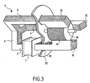
- FIG. 3 represents a partial perspective view of the engine on which appear the stator magnetic circuit 2 comprising the sections of cores 3, 4, 5 connected by the cylinder head 6, the core sections 11, 12 and 13, the rotor 14 with its axis 15, the electrical winding 7 mounted on the core section 3 and the plate 22 provided with a sealed crossing 18 for the passage of the section 11.
- the motor 1 of the invention has a vertical axis and comprises a stator magnetic circuit 2, electrical windings 7, 8, a carcass 19, a plate 22 and a rotor 14 as described for the first mode of realization and arranged in the same way.
- the shafts 15 and 27 are supported by bearings 16, 17 and 31, the bearings 16 and 17 being mechanically connected to the stator magnetic circuit at means of wedging pieces 41 and 42 as in the first embodiment, the bearing 31 and the stop 33 being integral with the extension 28 of the carcass 19.
- the extension 28 of the carcass 19 has an inlet 34 and a outlet 35 of the liquid circulated by the impeller 32 driven by the rotor 14 of the engine.
- stator chamber 20 immersed in a liquid by a very great depth, i.e. under pressure very high static, the stator chamber 20 is filled with a liquid.
- the pressures between the stator chamber 20 and the rotor chamber 30 balance each other and so the problems related to the difference in pressure between these two chambers disappear.
- the motor 1 of the invention has a vertical axis and comprises a stator magnetic circuit 2, electrical windings 7, 8, a carcass 19, a plate 22 and a rotor 14 as described for the first mode of realization and arranged in the same way.
- the watertight bushings referenced 18 in FIG. 1 are replaced by a shirt referenced 43 in the figure 5.
- This shirt 43 made of insulating and non-magnetic material, envelops the first part 2 of the stator magnetic circuit and is connected so sealed by a weld 44 to part 22 of the wall of the stator chamber 20.
- the sealing of the stator chamber 20 is guaranteed and the stator magnetic circuit is in the pressure conditions of the rotor chamber 30 which eliminates the problem of sealing the crossing of the part 22 of the wall of the rotor chamber 30 by the sheets of the stator magnetic circuit and in particular the seal between the sheets which can be difficult to achieve.
- stator windings and their mounting on the sections of magnetic cores their electrical isolation is not limited by the size of the notches as in conventional motors, and therefore they can be powered by voltages much higher than those of motors which avoids the use of a transformer near the motor when it is very far from its power source.
- the electric motor of the invention also has the advantage of not only have static seals that do not have the disadvantages of dynamic sealing devices, which gives it great reliability, essential for many applications where the engine is difficult to access, for example at the bottom of an oil production well submarine or in a hazardous area as is the case in industry nuclear and certain chemical industries manufacturing hazardous products.
- the electrical windings mounted in the sealed chamber 20 are completely isolated from the surrounding environment and the pumped fluid which makes them insensitive to mechanical and chemical attack linked to the nature of fluids pumped and the surrounding environment.
- the motor of the invention is particularly suitable for pumping hydrocarbons in multiphase form at the bottom of subsea production wells by very great depth.
Landscapes
- Engineering & Computer Science (AREA)
- Power Engineering (AREA)
- Mechanical Engineering (AREA)
- General Engineering & Computer Science (AREA)
- Connection Of Motors, Electrical Generators, Mechanical Devices, And The Like (AREA)
- Motor Or Generator Frames (AREA)
- Discharge Heating (AREA)
- Control Of Direct Current Motors (AREA)
- Motor And Converter Starters (AREA)
Description
- une première partie 2 constituée de trois tronçons de noyaux 3, 4 et 5, dont seulement les tronçons 3 et 4 sont visibles sur la figure 1, décalés dans l'espace de 120° et formant à une de leur extrémité une culasse 6.
- une deuxième partie 10, constituée de trois tronçons de noyaux 11, 12 et 13 qui prolongent les trois tronçons 3, 4 et 5, dont seulement 11 et 12 sont visibles sur la figure 1 et dont les extrémités forment un évidement cylindrique.
- un impulseur de pompe 32 muni d'un arbre 27 relié à l'extrémité de l'arbre 15 du rotor 14 et muni à son extrémité inférieure d'une butée axiale 33,
- un soufflet 40 de compensation de la différence de pression entre les deux faces de la plaque 22,
- un prolongement 28 de la carcasse 19 muni d'un fond 36, qui forme une chambre rotorique 30 qui enferme la deuxième partie 10 du circuit magnétique statorique, le rotor 14 et l'impulseur 32 de la pompe,
- une prise électrique 38 de soutirage d'énergie électrique qui passe au travers de la carcasse 21 par une traversée de câble étanche 37.
Claims (8)
- Moteur électrique à courant alternatif comportant un circuit magnétique statorique, qui comprend une première partie (2) sur laquelle sont montés des enroulements (7, 8) électriques et une deuxième partie (10) évidée, un rotor (14) cylindrique muni d'un axe de rotation (15) supporté par au moins deux paliers (16 et 17), ledit rotor étant disposé à l'intérieur de la partie évidée du circuit statorique, et une chambre statorique (20) à paroi étanche, dont au moins une partie est réalisée en un matériau isolant, à l'intérieur de laquelle sont montés la première partie (2) du circuit statorique et les enroulements (7, 8) électriques et à l'extérieur de laquelle se trouvent le rotor (14) cylindrique, son axe de rotation (15) et les paliers supports (16 et 17), lequel moteur est caractérisé en ce que la deuxième partie (10) du circuit statorique se trouve à l'extérieur de la chambre statorique (20) et en ce que cette deuxième partie (10) du circuit statorique, le rotor (14) cylindrique avec son axe de rotation (15) et les paliers supports (16 et 17) sont disposés de telle sorte à l'extérieur de la chambre statorique (20) que le circuit magnétique statorique traverse la paroi de ladite chambre dans la partie de cette paroi réalisée en matériau isolant, lequel matériau est un isolant amagnétique.
- Moteur selon la revendication 1, caractérisé en ce que l'axe (15) du rotor (14) dudit moteur étant relié mécaniquement à l'axe (27) du rotor (32) d'une pompe, la deuxième partie (10) du circuit magnétique statorique, le rotor (14) dudit moteur, les paliers (16 et 17) supports et le rotor (32) de la pompe sont enfermés dans une chambre rotorique (30) à paroi étanche munie d'une entrée (34) et d'une sortie (35) d'un fluide à pomper.
- Moteur selon l'une des revendications 1 ou 2 caractérisé en ce que la paroi étanche de la chambre statorique (20) comporte un dispositif (40) de compensation de la différence de pression entre l'intérieur et l'extérieur de ladite chambre
- Moteur selon l'une des revendications 1 à 3 caractérisé en ce que les enroulements (7, 8) électriques statoriques comportent au moins une prise (38) de soutirage d'énergie électrique.
- Moteur selon l'une des revendications 1 à 3 caractérisé en ce que le circuit magnétique statorique comporte un enroulement électrique supplémentaire pour soutirer ce l'énergie électrique.
- Moteur selon l'une des revendications 1 à 5 caractérisé en ce qu'il comporte en plus un piquage (23) d'entrée et un piquage (24) de sortie montés sur la paroi de la chamore statorique (20) pour raccorder un dispositif extérieur de refroidissement d'un fluide remplissant la chambre statorique (20).
- Moteur selon l'une des revendications 1 à 6, caractérisé en ce qu'il comporte en plus une chemise (43) réalisée en matériau isolant amagnétique qui enveloppe la première partie (2) du circuit magnétique statorique, raccordée de manière étanche à la partie (22) réalisée en matériau isolant amagnétique de la paroi de la chambre (20) pour rendre ladite chambre étanche.
- Moteur selon l'une des revendications 1 à 7, caractérisé en ce que les paliers (16 et 17), qui supportent l'axe de rotation (15) du rotor (14), sont reliés mécaniquement à la deuxième partie (10) du circuit magnétique, statoriquc par des pièces de calage (41 et 42) en un matériau isolant et amagnétique.
Applications Claiming Priority (3)
| Application Number | Priority Date | Filing Date | Title |
|---|---|---|---|
| FR9911076A FR2798232B1 (fr) | 1999-09-03 | 1999-09-03 | Moteur electrique a courant alternatif |
| FR9911076 | 1999-09-03 | ||
| PCT/FR2000/002410 WO2001018942A1 (fr) | 1999-09-03 | 2000-08-31 | Moteur electrique a courant alternatif |
Publications (2)
| Publication Number | Publication Date |
|---|---|
| EP1214773A1 EP1214773A1 (fr) | 2002-06-19 |
| EP1214773B1 true EP1214773B1 (fr) | 2003-10-29 |
Family
ID=9549537
Family Applications (1)
| Application Number | Title | Priority Date | Filing Date |
|---|---|---|---|
| EP00960767A Expired - Lifetime EP1214773B1 (fr) | 1999-09-03 | 2000-08-31 | Moteur electrique a courant alternatif |
Country Status (6)
| Country | Link |
|---|---|
| US (1) | US6765325B1 (fr) |
| EP (1) | EP1214773B1 (fr) |
| DE (1) | DE60006264T2 (fr) |
| FR (1) | FR2798232B1 (fr) |
| NO (1) | NO314968B1 (fr) |
| WO (1) | WO2001018942A1 (fr) |
Families Citing this family (22)
| Publication number | Priority date | Publication date | Assignee | Title |
|---|---|---|---|---|
| JP4887652B2 (ja) * | 2005-04-21 | 2012-02-29 | ソニー株式会社 | 噴流発生装置及び電子機器 |
| ATE528838T1 (de) * | 2005-08-30 | 2011-10-15 | Askoll Holding Srl | Einphasiger permanentmagetischer synchronmotor mit verbesserter statorstruktur, insbesondere für entwässerungspumpen von waschmaschinen und ähnlichen hausgeräten |
| US7459817B2 (en) * | 2006-08-15 | 2008-12-02 | Bombardier Transportation Gmbh | Semi-enclosed AC motor |
| CN201165985Y (zh) * | 2007-10-22 | 2008-12-17 | 李明玉 | 可提供低压电源的潜水泵 |
| CN103236753A (zh) * | 2013-05-09 | 2013-08-07 | 东华大学 | 一种基于密封结构的干式开关磁阻电机 |
| CN103219846A (zh) * | 2013-05-09 | 2013-07-24 | 东华大学 | 一种基于密封结构的充油式三相交流异步电机及应用 |
| CN103236754A (zh) * | 2013-05-09 | 2013-08-07 | 东华大学 | 一种基于密封结构的充油式开关磁阻电机 |
| CN103236755A (zh) * | 2013-05-09 | 2013-08-07 | 东华大学 | 一种基于密封结构的充油式永磁同步电机 |
| CN103219844A (zh) * | 2013-05-09 | 2013-07-24 | 东华大学 | 一种基于密封结构的干式单相交流异步电机及应用 |
| CN103227541A (zh) * | 2013-05-09 | 2013-07-31 | 东华大学 | 一种基于密封结构的充水式单相交流异步电机及应用 |
| CN103227520A (zh) * | 2013-05-09 | 2013-07-31 | 东华大学 | 一种基于密封结构的充水式开关磁阻电机 |
| CN103266366A (zh) * | 2013-05-09 | 2013-08-28 | 东华大学 | 一种细纱机电机式锭子 |
| CN103354411A (zh) * | 2013-05-09 | 2013-10-16 | 东华大学 | 一种基于密封结构的充水式永磁同步电机 |
| CN103219854A (zh) * | 2013-05-09 | 2013-07-24 | 东华大学 | 一种基于密封结构的干式异步启动永磁同步电机 |
| CN103219853A (zh) * | 2013-05-09 | 2013-07-24 | 东华大学 | 一种基于密封结构的充水式异步启动永磁同步电机 |
| CN103219845A (zh) * | 2013-05-09 | 2013-07-24 | 东华大学 | 一种基于密封结构的充油式单相交流异步电机及应用 |
| CN103236768A (zh) * | 2013-05-09 | 2013-08-07 | 东华大学 | 一种基于密封结构的充水式三相交流异步电机及应用 |
| CN103227543A (zh) * | 2013-05-09 | 2013-07-31 | 东华大学 | 一种基于密封结构的干式永磁同步电机 |
| CN103259381A (zh) * | 2013-05-09 | 2013-08-21 | 东华大学 | 一种基于密封结构的干式三相交流异步电机及应用 |
| CN103236770A (zh) * | 2013-05-09 | 2013-08-07 | 东华大学 | 一种基于密封结构的充油式异步启动永磁同步电机 |
| CN103572430B (zh) * | 2013-08-13 | 2016-01-20 | 东华大学 | 一种基于定子绕组防尘的细纱机电机式锭子及其制造方法 |
| US20200220439A1 (en) * | 2016-12-30 | 2020-07-09 | Axel Michael Sigmar | Integrated Adaptive Polyphase Electric Motor |
Family Cites Families (7)
| Publication number | Priority date | Publication date | Assignee | Title |
|---|---|---|---|---|
| FR973151A (fr) * | 1941-06-26 | 1951-02-08 | Perfectionnements aux moteurs électriques | |
| FR916681A (fr) * | 1945-10-31 | 1946-12-12 | Nouveau moteur électrique pouvant être immergé dans l'eau | |
| US4030358A (en) * | 1975-11-10 | 1977-06-21 | Cambridge Filter Corporation | Portable air velocity measuring unit |
| US4030058A (en) * | 1976-03-30 | 1977-06-14 | Westinghouse Electric Corporation | Inductive coupler |
| DE3423777A1 (de) * | 1984-06-28 | 1986-01-02 | Philips Patentverwaltung Gmbh, 2000 Hamburg | Zweipoliger einphasensynchronmotor mit permanentmagnetischem rotor (modulmotor) |
| US5134328A (en) * | 1991-04-04 | 1992-07-28 | Baker Hughes Incorporated | Submersible pump protection for hostile environments |
| IT1259848B (it) * | 1992-11-27 | 1996-03-28 | Hydor Srl | Motore elettrico sincrono, particolarmente per pompe immergibili e pompa incorporante tale motore |
-
1999
- 1999-09-03 FR FR9911076A patent/FR2798232B1/fr not_active Expired - Fee Related
-
2000
- 2000-08-31 EP EP00960767A patent/EP1214773B1/fr not_active Expired - Lifetime
- 2000-08-31 WO PCT/FR2000/002410 patent/WO2001018942A1/fr not_active Ceased
- 2000-08-31 US US10/069,887 patent/US6765325B1/en not_active Expired - Lifetime
- 2000-08-31 DE DE60006264T patent/DE60006264T2/de not_active Expired - Lifetime
-
2002
- 2002-03-01 NO NO20021044A patent/NO314968B1/no not_active IP Right Cessation
Also Published As
| Publication number | Publication date |
|---|---|
| US6765325B1 (en) | 2004-07-20 |
| EP1214773A1 (fr) | 2002-06-19 |
| FR2798232A1 (fr) | 2001-03-09 |
| FR2798232B1 (fr) | 2001-11-16 |
| NO314968B1 (no) | 2003-06-16 |
| NO20021044D0 (no) | 2002-03-01 |
| DE60006264T2 (de) | 2004-08-05 |
| NO20021044L (no) | 2002-05-02 |
| DE60006264D1 (de) | 2003-12-04 |
| WO2001018942A1 (fr) | 2001-03-15 |
Similar Documents
| Publication | Publication Date | Title |
|---|---|---|
| EP1214773A1 (fr) | Moteur electrique a courant alternatif | |
| EP0412858B1 (fr) | Groupe Motopompe électrique à tube d'entrefer | |
| US7504752B2 (en) | Electric motors for powering downhole tools | |
| EP0793330B1 (fr) | Générateur d'énergie électrique en ligne autonome | |
| CN100335795C (zh) | 尤其适用于泵的电机 | |
| EP0704599A1 (fr) | Installation pour puits pétrolier munie d'une électropompe en fond de puits | |
| EP1645021B1 (fr) | Refroidissement d'un stator | |
| WO1999014503A1 (fr) | Pompe rotative a rotor immerge | |
| ITVI920181A1 (it) | Motore elettrico sincrono, particolarmente per pompe immergibili e pompa incorporante tale motore | |
| FR2487446A1 (fr) | Groupe de pompage electrique a palette, a joint d'huile, d'encombrement reduit | |
| NO348770B1 (en) | Magnetic Coupling for Motor Drive Shaft of Electrical Submersible Pump | |
| WO2021038168A1 (fr) | Machine à bobinage toroïdal | |
| RU2083047C1 (ru) | Герметизированный электродвигатель погружной "сухого" типа для скважинного насоса | |
| WO2020002817A1 (fr) | Machine tournante supraconductrice | |
| FR2527854A1 (fr) | Moteur a courant continu fonctionnant immerge | |
| SU1350382A1 (ru) | Погружна насосна установка | |
| FR2513710A1 (fr) | Ensemble d'entrainement synchrone par voie magnetique avec cloison separatrice feuilletee | |
| FR2582165A1 (fr) | Machine multipolaire a courant continu pour utilisation en immersion | |
| US20260098536A1 (en) | Submersible motor, submersible pump and silent water pump | |
| RU27652U1 (ru) | Погружной скважинный электронасос | |
| WO2024251958A1 (fr) | Moteur électrique à assemblage amélioré | |
| EP3379172B1 (fr) | Installation cryogénique comprenant un circulateur | |
| SU1707696A1 (ru) | Глубоководный силовой электроагрегат | |
| FR2593002A1 (fr) | Pompe electromagnetique pour liquide conducteur a refoulement par repulsion magnetique. | |
| JP2016181951A (ja) | モータ |
Legal Events
| Date | Code | Title | Description |
|---|---|---|---|
| PUAI | Public reference made under article 153(3) epc to a published international application that has entered the european phase |
Free format text: ORIGINAL CODE: 0009012 |
|
| 17P | Request for examination filed |
Effective date: 20020403 |
|
| AK | Designated contracting states |
Kind code of ref document: A1 Designated state(s): AT BE CH CY DE DK ES FI FR GB GR IE IT LI LU MC NL PT SE |
|
| GRAH | Despatch of communication of intention to grant a patent |
Free format text: ORIGINAL CODE: EPIDOS IGRA |
|
| GRAS | Grant fee paid |
Free format text: ORIGINAL CODE: EPIDOSNIGR3 |
|
| GRAA | (expected) grant |
Free format text: ORIGINAL CODE: 0009210 |
|
| AK | Designated contracting states |
Kind code of ref document: B1 Designated state(s): CH DE GB IT LI |
|
| REG | Reference to a national code |
Ref country code: GB Ref legal event code: FG4D Free format text: NOT ENGLISH |
|
| REG | Reference to a national code |
Ref country code: CH Ref legal event code: EP |
|
| REG | Reference to a national code |
Ref country code: CH Ref legal event code: NV Representative=s name: PATMED AG |
|
| REG | Reference to a national code |
Ref country code: IE Ref legal event code: FG4D Free format text: FRENCH |
|
| REF | Corresponds to: |
Ref document number: 60006264 Country of ref document: DE Date of ref document: 20031204 Kind code of ref document: P |
|
| GBT | Gb: translation of ep patent filed (gb section 77(6)(a)/1977) |
Effective date: 20031209 |
|
| REG | Reference to a national code |
Ref country code: IE Ref legal event code: FD4D |
|
| PLBE | No opposition filed within time limit |
Free format text: ORIGINAL CODE: 0009261 |
|
| STAA | Information on the status of an ep patent application or granted ep patent |
Free format text: STATUS: NO OPPOSITION FILED WITHIN TIME LIMIT |
|
| 26N | No opposition filed |
Effective date: 20040730 |
|
| PGFP | Annual fee paid to national office [announced via postgrant information from national office to epo] |
Ref country code: CH Payment date: 20150721 Year of fee payment: 16 Ref country code: DE Payment date: 20150722 Year of fee payment: 16 Ref country code: GB Payment date: 20150724 Year of fee payment: 16 |
|
| PGFP | Annual fee paid to national office [announced via postgrant information from national office to epo] |
Ref country code: IT Payment date: 20150728 Year of fee payment: 16 |
|
| REG | Reference to a national code |
Ref country code: DE Ref legal event code: R119 Ref document number: 60006264 Country of ref document: DE |
|
| REG | Reference to a national code |
Ref country code: CH Ref legal event code: PL |
|
| GBPC | Gb: european patent ceased through non-payment of renewal fee |
Effective date: 20160831 |
|
| PG25 | Lapsed in a contracting state [announced via postgrant information from national office to epo] |
Ref country code: CH Free format text: LAPSE BECAUSE OF NON-PAYMENT OF DUE FEES Effective date: 20160831 Ref country code: LI Free format text: LAPSE BECAUSE OF NON-PAYMENT OF DUE FEES Effective date: 20160831 |
|
| PG25 | Lapsed in a contracting state [announced via postgrant information from national office to epo] |
Ref country code: DE Free format text: LAPSE BECAUSE OF NON-PAYMENT OF DUE FEES Effective date: 20170301 Ref country code: GB Free format text: LAPSE BECAUSE OF NON-PAYMENT OF DUE FEES Effective date: 20160831 |
|
| PG25 | Lapsed in a contracting state [announced via postgrant information from national office to epo] |
Ref country code: IT Free format text: LAPSE BECAUSE OF NON-PAYMENT OF DUE FEES Effective date: 20160831 |