EP1215444B2 - Dispositif de four et procédé de commande d'un four - Google Patents
Dispositif de four et procédé de commande d'un four Download PDFInfo
- Publication number
- EP1215444B2 EP1215444B2 EP01403103A EP01403103A EP1215444B2 EP 1215444 B2 EP1215444 B2 EP 1215444B2 EP 01403103 A EP01403103 A EP 01403103A EP 01403103 A EP01403103 A EP 01403103A EP 1215444 B2 EP1215444 B2 EP 1215444B2
- Authority
- EP
- European Patent Office
- Prior art keywords
- temperature
- cooking
- oven
- interior space
- air
- Prior art date
- Legal status (The legal status is an assumption and is not a legal conclusion. Google has not performed a legal analysis and makes no representation as to the accuracy of the status listed.)
- Expired - Lifetime
Links
- 238000000034 method Methods 0.000 title claims description 14
- XLYOFNOQVPJJNP-UHFFFAOYSA-N water Substances O XLYOFNOQVPJJNP-UHFFFAOYSA-N 0.000 claims abstract description 17
- 238000010411 cooking Methods 0.000 claims description 65
- 239000003570 air Substances 0.000 claims description 24
- 238000001816 cooling Methods 0.000 claims description 20
- 238000010438 heat treatment Methods 0.000 claims description 13
- 235000013305 food Nutrition 0.000 claims description 3
- 239000012080 ambient air Substances 0.000 claims description 2
- 238000002347 injection Methods 0.000 claims description 2
- 239000007924 injection Substances 0.000 claims description 2
- 230000000153 supplemental effect Effects 0.000 claims 1
- 235000015278 beef Nutrition 0.000 description 21
- 239000000523 sample Substances 0.000 description 5
- 230000004580 weight loss Effects 0.000 description 5
- 238000004140 cleaning Methods 0.000 description 4
- 238000012423 maintenance Methods 0.000 description 4
- 230000015654 memory Effects 0.000 description 4
- 235000014594 pastries Nutrition 0.000 description 4
- 230000009471 action Effects 0.000 description 3
- 230000008901 benefit Effects 0.000 description 3
- 238000009833 condensation Methods 0.000 description 3
- 230000005494 condensation Effects 0.000 description 3
- 238000007599 discharging Methods 0.000 description 3
- 230000002829 reductive effect Effects 0.000 description 3
- 235000013311 vegetables Nutrition 0.000 description 3
- 241000251468 Actinopterygii Species 0.000 description 2
- 241000894006 Bacteria Species 0.000 description 2
- 241000238424 Crustacea Species 0.000 description 2
- 238000004040 coloring Methods 0.000 description 2
- 230000006378 damage Effects 0.000 description 2
- 238000001035 drying Methods 0.000 description 2
- 238000000265 homogenisation Methods 0.000 description 2
- 239000012774 insulation material Substances 0.000 description 2
- 230000000670 limiting effect Effects 0.000 description 2
- 235000012054 meals Nutrition 0.000 description 2
- 235000013372 meat Nutrition 0.000 description 2
- 238000012544 monitoring process Methods 0.000 description 2
- 239000007921 spray Substances 0.000 description 2
- 230000006641 stabilisation Effects 0.000 description 2
- 238000011105 stabilization Methods 0.000 description 2
- 238000012360 testing method Methods 0.000 description 2
- 238000010257 thawing Methods 0.000 description 2
- 238000012546 transfer Methods 0.000 description 2
- 235000001808 Ceanothus spinosus Nutrition 0.000 description 1
- 241001264786 Ceanothus spinosus Species 0.000 description 1
- 240000007594 Oryza sativa Species 0.000 description 1
- 235000007164 Oryza sativa Nutrition 0.000 description 1
- 244000061456 Solanum tuberosum Species 0.000 description 1
- 235000002595 Solanum tuberosum Nutrition 0.000 description 1
- 230000002411 adverse Effects 0.000 description 1
- 238000013459 approach Methods 0.000 description 1
- 230000006399 behavior Effects 0.000 description 1
- 230000033228 biological regulation Effects 0.000 description 1
- 230000015572 biosynthetic process Effects 0.000 description 1
- 230000000740 bleeding effect Effects 0.000 description 1
- 235000008429 bread Nutrition 0.000 description 1
- 238000003763 carbonization Methods 0.000 description 1
- 230000008859 change Effects 0.000 description 1
- 230000003749 cleanliness Effects 0.000 description 1
- 238000004891 communication Methods 0.000 description 1
- 230000007423 decrease Effects 0.000 description 1
- 230000003247 decreasing effect Effects 0.000 description 1
- 235000021186 dishes Nutrition 0.000 description 1
- 230000000694 effects Effects 0.000 description 1
- 230000005611 electricity Effects 0.000 description 1
- 238000005265 energy consumption Methods 0.000 description 1
- 238000001704 evaporation Methods 0.000 description 1
- 230000008020 evaporation Effects 0.000 description 1
- 238000010304 firing Methods 0.000 description 1
- 235000011389 fruit/vegetable juice Nutrition 0.000 description 1
- 239000004519 grease Substances 0.000 description 1
- 239000007788 liquid Substances 0.000 description 1
- 238000011068 loading method Methods 0.000 description 1
- 230000007774 longterm Effects 0.000 description 1
- 230000008520 organization Effects 0.000 description 1
- 235000015927 pasta Nutrition 0.000 description 1
- 235000012015 potatoes Nutrition 0.000 description 1
- 230000008569 process Effects 0.000 description 1
- 235000020989 red meat Nutrition 0.000 description 1
- 230000008929 regeneration Effects 0.000 description 1
- 238000011069 regeneration method Methods 0.000 description 1
- 238000003303 reheating Methods 0.000 description 1
- 230000000284 resting effect Effects 0.000 description 1
- 235000009566 rice Nutrition 0.000 description 1
- 229920006395 saturated elastomer Polymers 0.000 description 1
- 235000015067 sauces Nutrition 0.000 description 1
- 238000010186 staining Methods 0.000 description 1
- 229910001220 stainless steel Inorganic materials 0.000 description 1
- 239000010935 stainless steel Substances 0.000 description 1
- 238000010025 steaming Methods 0.000 description 1
- 230000001052 transient effect Effects 0.000 description 1
- 238000009423 ventilation Methods 0.000 description 1
- 238000010792 warming Methods 0.000 description 1
Images

Classifications
-
- F—MECHANICAL ENGINEERING; LIGHTING; HEATING; WEAPONS; BLASTING
- F24—HEATING; RANGES; VENTILATING
- F24C—DOMESTIC STOVES OR RANGES ; DETAILS OF DOMESTIC STOVES OR RANGES, OF GENERAL APPLICATION
- F24C15/00—Details
- F24C15/20—Removing cooking fumes
- F24C15/2007—Removing cooking fumes from oven cavities
-
- A—HUMAN NECESSITIES
- A21—BAKING; EDIBLE DOUGHS
- A21B—BAKERS' OVENS; MACHINES OR EQUIPMENT FOR BAKING
- A21B3/00—Parts or accessories of ovens
- A21B3/04—Air-treatment devices for ovens, e.g. regulating humidity
-
- F—MECHANICAL ENGINEERING; LIGHTING; HEATING; WEAPONS; BLASTING
- F24—HEATING; RANGES; VENTILATING
- F24C—DOMESTIC STOVES OR RANGES ; DETAILS OF DOMESTIC STOVES OR RANGES, OF GENERAL APPLICATION
- F24C15/00—Details
- F24C15/32—Arrangements of ducts for hot gases, e.g. in or around baking ovens
- F24C15/322—Arrangements of ducts for hot gases, e.g. in or around baking ovens with forced circulation
- F24C15/327—Arrangements of ducts for hot gases, e.g. in or around baking ovens with forced circulation with air moisturising
Definitions
- the present invention relates to the field of control processes for ovens, in particular culinary, of individual type, for example for the equipment of the home, of collective type, for example for a school canteen or business, or industrial for the prepared meals in the agri-food sector.
- the cooking of certain foods causes delicate problems of temperature control and cooking behavior, due to changes in appearance and taste that they are likely to undergo.
- the cooking of red meat, such as roast beef is one of the most delicate.
- the user or the consumer may wish a blue cooking, bleeding or point, also called "well cooked".
- the temperature difference at the heart of the roast between these three types of cooking is of the order of 1 or 2 ° C.
- the so-called "classic" cooking is known in a dry atmosphere or in the presence of steam, at an elevated temperature that is very much greater than the desired core temperature in the product.
- the setting of the oven is simple: a temperature and a duration are determined. A temperature probe stuck in the middle of the roast can help define the end of cooking. The cooking time is short.
- the roast has the desired external appearance with a heart more or less red or pink and a slightly grilled outer crust.
- the roast beef can be directly sliced and served without further operation.
- the principle of cooking in a vapor atmosphere at a slightly higher temperature (2 to 3 ° C.) than the desired core temperature is also known. This provides a great deal of control over the degree of cooking.
- the end time of cooking does not need to be particularly precise, given that the internal temperature of the oven is substantially equal to the desired core temperature. It is therefore not necessary to provide a rest period at the exit of the oven.
- the appearance of the roast beef after slicing is well controlled.
- the taste aspects, the tenderness and the juiciness are very well preserved regardless of the size of the roast beef and the load of the oven, that is to say the number of roast beef cooked at the same time.
- the destruction of the bacteria of the meat is very well ensured because of the long duration of the cooking.
- the weight loss of roast beef is greatly reduced.
- the cooking lasts several hours, which immobilizes an oven longer.
- Roast beef does not have the grilled appearance that can be desired by the consumer. It can therefore be the subject of a subsequent treatment of coloring, sauce, etc.
- This type of cooking does not require sophisticated means, with the exception of very precise temperature control.
- the cooking can be carried out in a bag in a water bath whose water temperature is well controlled.
- the present invention seeks to combine the advantages of the two types of cooking presented above and obviate their disadvantages.
- the present invention provides a furnace control method suitable for both short cooking and long cooking that can be performed at night in the absence of staff.
- the furnace control method according to the invention comprises the features of claim 1.
- the cooling means of the oven controlled by the method comprises a means for discharging hot air from the interior space.
- the cooling means may comprise a valve disposed between the pump and the interior space in the direction of the flow of air and able to be closed when the pump is stopped and to be opened when the pump is running.
- the valve makes it possible to avoid unwanted air flows out of the cooling phase.
- the pump can be centrifugal type.
- the cooling means comprises a water injection means. It is thus possible to lower the temperature of the heating means very rapidly, for example electrical resistances, thanks to the high heat capacity of the water. It is therefore particularly advantageous to provide a projection of water on an electrical heating resistor.
- the projection can be provided by a fan and can also be directed towards the walls of the interior space which have a certain thermal inertia because of their thickness and insulation materials arranged around.
- the furnace control method according to the invention provides for triggering a step of forced cooling of the interior space of an oven initially at a first temperature. Cooling is continued to a second temperature below the first temperature.
- cooling air is taken from an external medium, for example ambient air.
- the second temperature will be higher than the ambient temperature outside the oven.
- an additional forced cooling step can be provided up to a third temperature lower than the second temperature followed by a holding step at the third temperature.
- Other similar steps towards lower and lower temperatures can be implemented.
- the humidity in the interior space is estimated and controlled.
- the forced cooling step includes a spray of water inside the oven which is particularly effective when the temperature in the interior space is greater than 100 °, and an air flow with cold air inlet and hot air outlet, more efficient for temperatures below 100 °.
- a means for heating the interior space of the oven controlled by the method of the invention is able to operate in a number n of nonzero heating powers.
- T e a temperature of the interior space
- T c a set temperature
- BP1 a temperature range
- the heating power P is set to the maximum power P max . If the temperature T e lies between T c - BP i and T c - BP i + 1 with i between 1 and n, then P is equal to j / nx P max .
- n 3 can be used.
- the slope is calculated for each temperature variation of 0.5 ° C.
- the principle of cooking by phases of temperature and of determined duration makes it possible to chain phases of coloring, of cooking with heart and of possible maintenance with a complete control of all the parameters making it possible to obtain an optimal quality and obtaining in a short time the benefits of long-term cooking.
- the first phase of cooking at high temperature allows the formation of a crust that limits weight loss and presents the usual appearance of the roast beef. Cooling prevents the outer areas of the roast beef from transmitting excessive heat to the heart area.
- the temperature maintenance phase makes it possible to precisely determine the core cooking temperature.
- the product can remain in the holding phase for a very variable time, given a temperature equivalent to the desired core temperature and the absence of the adverse heat transfer effects between a warmer zone and a less hot zone and the absence of rest time necessary for the homogenization of temperatures.
- Tenderness and juiciness are optimal.
- the taste aspects are preserved, regardless of the size of the product and the load of the oven.
- the pasteurizing values obtained are high, which guarantees a satisfactory destruction of the bacteria.
- the clogging of the oven is reduced and the low temperature cooking phase in a steam environment prevents carbonization of the projections and their adhesion to the walls of the oven. It is thus possible to reduce the weight losses of the products to be cooked and to reduce the time and thus the cost of cleaning the oven after cooking.
- the products are cooked in the evening before the operators leave and are taken out of the ovens the next day when they have to be served.
- the energy consumption of the furnace is then carried out at night electric tariff, generally cheap.
- the oven is used in masked time, without staff, which facilitates the organization of a team with low working time.
- the oven is operated outside staff time slots for better depreciation.
- the products can be taken out of the oven as soon as the staff arrives in the morning. The oven is then available for cooking other products.
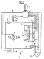
- the oven 1 comprises an enclosure 2 defining an interior space 3.
- the enclosure 2 is provided with a door, not shown, and is of insulated type, comprising, as is known, an outer wall, an inner wall and a insulation material disposed between the outer wall and the inner wall.
- the outer and inner walls can be made of stainless steel sheet.
- the interior space 3 can be arranged grids, not shown, for arranging dishes or products to be cooked.
- Roasters 4 are represented here, of different sizes from each other.
- the oven 1 comprises a sensor 5 of the temperature T e of the interior space 3, a sensor 6 of the temperature T p at the heart of the products to be cooked 4, which is in the form of a probe that can be stitched in the product 4, and a sensor 7 for measuring the temperature T 1 of the liquid which condenses in the interior space 3.
- the sensors 5, 6 and 7 are connected, for example by son, to a computing unit 8 able to interpret the received data.
- the computing unit 8 comprises a microprocessor, one or more memories, a communication bus between the microprocessor and the memory and one or more software stored in the memory and able to be executed by the microprocessor.
- the central unit 8 is associated with a control panel 9 allowing the display of information, for example the temperature T e of the interior space 3 measured by the sensor 5, and control buttons which will be explained in more detail. detail with reference to the figure 5 .
- the oven 1 further comprises a plurality of heating resistors 10, here three, of generally circular shape, and controlled, one by an interface 11, for example an electromechanical relay, and the other two by an interface 12 which can be of the same kind.
- the interfaces 11 and 12 are connected to the calculation unit 8.
- a centrifugal fan 13 is arranged in the circular space between the resistors 10 and is driven by a motor 14 also connected and controlled by the calculation unit 8.
- a nozzle 15 connected to a pipe 16 on which is disposed a solenoid valve 17 connected and controlled by the central unit 8.
- the opening of the solenoid valve 17 allows to project water by the nozzle 15 on the blades of the fan 13. The water is thus projected during the rotation of the fan 13 on the resistors 10 and turns into steam, which increases the moisture content in the interior space 3.
- the temperature variations inside the oven 1 may cause condensation phenomena, for example during the gradual cooling of the oven starting from a state close to the saturation of steam. Condensates are then formed on the walls of the oven, which flow downwards through a pipe 18 on which the sensor 7 for measuring the temperature of the condensates is mounted.
- the oven 1 further comprises a discharge chimney 19 mounted in an upper part of the enclosure 2 and equipped with a movable valve 20 under the action of an actuator 21, for example an electric motor, connected to the central unit 8.
- the valve 20 can be closed, which prevents the circulation of air between the interior space 3 and the ambient atmosphere, or open.
- the oven 1 comprises a fan 22, for example of centrifugal type, driven by an engine electrical, not shown, and whose outlet opens into the interior space 3 and can be closed by a valve 23 controlled by an actuator 24, for example an electric motor, via a rod 25.
- the actuator 24 is connected to the central unit 8.
- the resistors 10 allow the temperature of the internal space 3 to be raised.
- the heating power can be adjusted to 1/3 of the maximum power by supplying only one of the resistors 10 via the interface 11 to the 2/3 of the maximum power through the interface 12, and the maximum power through the two interfaces 11 and 12.
- the fan 13 allows air circulation in the interior space 3 and a distribution of the heat produced by the resistors 10.
- the fan 13 also allows, in association with the water projection means, to raise the humidity level in the interior space 3 by distributing the water on the resistances 10 , which causes the immediate evaporation of water.
- the pipe 18 allows the evacuation of the condensates.
- the means for introducing cold air formed by the fan 22 and the associated elements and the means for discharging hot air formed by the valve 20 and the associated elements allow rapid cooling of the interior space 3 by introduction a large volume of cold air and discharge of a corresponding amount of hot air, for example at a rate of the order of several tens of m 3 / h.
- the interior of the oven is at an elevated temperature, for example greater than 100 ° C.
- the projection of water through the nozzle 15 makes it possible to cool very quickly the resistors 10 whose supply has been cut off, and also to cool the inner walls of the enclosure 2 which can be at very high temperatures. In this case, part of the water projected by the nozzle 15 will be vaporized and escape through the pipe 19 and the valve 20, while another part will condense and be evacuated through the discharge pipe 18.
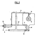
- FIG 2 there is shown a variant in which there is provided another solenoid valve 26 mounted next to the solenoid valve 17 on a water inlet pipe.
- the solenoid valve 26 is connected to a pipe 27 which supplies a nozzle 28 disposed in the pipe 18 for discharging the condensates. It is thus possible to spray water into the pipe 18, which guarantees a good condensation of the vapor that may escape through said pipe 18, in the case where the valves 20 and 23 are closed and a large amount of steam is present in the interior space 3.
- the sensor 7 has not been shown on the figure 2 .
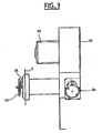
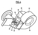
- the fan 22 is rotated by an electric motor 29 and has an air inlet 30.
- the figure 4 is partially exploded to better see the rod 25 provided at its end opposite the valve 23 of a bearing surface 31.
- the actuator 24 comprises an electric motor 32, capable of rotating a cam 33 in contact with the bearing surface 31.
- a spring is associated with the rod 25 to bring the bearing surface 31 in contact with the cam 33.
- the motor 32 may be of the step type. In a first position, the valve 23 will be open, see figure 3 . In another position, the cam 33 having rotated at an angle of 180 ° C, the bearing surface 31 could have moved away from the chamber 2, causing the rod 25 and the valve 23 which will therefore moved towards the enclosure 2 in a closed position.
- the button 34 has a stop position, a start position, a cooling position and an automatic cleaning position.
- the button 35 allows the choice of the operating mode, for example a dry cooking with forced air from 0 to 250 ° C, a mixed cooking with pulsed air and steam from 30 to 210 ° C, superheated steam cooking at 105 ° C, steaming at 30 to 98 ° C and reheating.
- the button 36 is used to adjust the set temperature T c .
- a display 43 is placed nearby and displays the measured temperature T e .
- Button 37 is used to set the cooking time or core temperature. Nearby, there is a display 44 of duration and a display 45 of core temperature.
- the button 38 is used to choose the end of cooking mode, with an end of cooking determined by the core temperature sensor 6, a timer, or a manual control.
- the knob 39 makes it possible to regulate the speed of rotation of the fan 13.
- the button 40 makes it possible to regulate the humidity level in the interior space 3.
- a humidity display 46 is placed nearby. The moisture content can be measured by a sensor that has not been represented on the figure 1 .
- the button 41 makes it possible to choose a cooking program number with display of the number selected on the display 47 located nearby.
- the button 48 makes it possible to choose a cycle number, a cycle being understood as a part of a program.
- a user will start by turning the oven on by the button 34, then choose a preheating program by means of the button 41 and start the heating by means of the button 34. Finally, after loading the oven products to to cook, he will choose a cooking program by means of the button 41 and start the cooking by means of the button 34.
- Dry cooking is particularly used for pastry and pastries that need to be dried.
- Mixed cooking is used for rotisserie, pastries that need to be moistened, crustaceans, and fish.
- the superheated steam position saves 10 to 20% more time compared to the steam mode, for delicate products such as potatoes, crustaceans, frozen green vegetables.
- Steam cooking is used for defrosting, vegetable and fish cooking, low temperature cooking and vacuum products.
- the plate regeneration position is used to heat the dried plates and trays without drying them.
- the temperature setpoint can be changed between 100 and 140 ° C in general. It is possible to provide a heating cycle for the plates limiting the condensation thereon.
- the display 43 indicates the set temperature T c .
- An action on this button causes the actual oven temperature to be displayed. The display is lit when the oven is warming up and off when the set temperature T c is reached.
- roast beef with very different weights can be cooked in the same way, with the same temperatures and durations, which represents an important economy of the manpower required by the monitoring of cooking in a standard oven.
- the oven according to the invention is suitable for cooking all types of food and can be provided for up to a hundred programs suitable for different types of meat, vegetables, breads and pastries, complete plates, defrosting, etc.
- the central control unit 8 for controlling the oven 1 can be provided with a PID type control, with a term integral weak and a strong derivative term for precise regulation. Depending on the possible powers P max / 3, 2P max / 3 and P max , proportional power control bands are provided.
- the proportional bands BP1 and BP2 depend on the slope p of the temperature curve of the interior space.
- the slope p is continuously calculated from the average of the last five calculated instantaneous slope values.
- the instantaneous slope is calculated by measuring the time required for the temperature to vary by 0.5 ° C If the duration is less than 3 seconds for a variation of 0.5 ° C, then the duration will be measured for a variation of 1 ° vs. If the duration is less than 3 seconds for a variation of 1 ° C, then the duration will be measured for a variation of 2 ° C. If the duration is less than 3 seconds for a variation of 2 ° C, then the duration will be measured for a variation of 4 ° C.
- the power level is decreased, it is that is to say that we switch to the higher power until at least the attainment of the set point. If, after crossing the setpoint T c , the temperature exceeds by 1 ° C said setpoint T c , it returns to the lower power level, otherwise it remains downgraded power.
Landscapes
- Engineering & Computer Science (AREA)
- Combustion & Propulsion (AREA)
- Mechanical Engineering (AREA)
- General Engineering & Computer Science (AREA)
- Chemical & Material Sciences (AREA)
- Life Sciences & Earth Sciences (AREA)
- Food Science & Technology (AREA)
- Electric Ovens (AREA)
- Commercial Cooking Devices (AREA)
- Baking, Grill, Roasting (AREA)
- Control Of Temperature (AREA)
- General Preparation And Processing Of Foods (AREA)
- Cookers (AREA)
- Electric Stoves And Ranges (AREA)
- Devices That Are Associated With Refrigeration Equipment (AREA)
- Control Of Heat Treatment Processes (AREA)
- Control Of High-Frequency Heating Circuits (AREA)
Description
- La présente invention concerne le domaine des procédés de commande de fours, notamment culinaires, de type individuel, par exemple pour l'équipement de la maison, de type collectif, par exemple pour une cantine scolaire ou d'entreprise, ou encore industriel pour la préparation de plats cuisinés dans le domaine agroalimentaire.
- La cuisson de certains aliments pose des problèmes délicats de réglage de température et de conduite de la cuisson, en raison de modifications d'aspect et de goût importantes qu'ils sont susceptibles de subir. La cuisson de la viande rouge, telle que le rosbif, est une des plus délicate. L'utilisateur ou le consommateur peut souhaiter une cuisson bleue, saignante ou à point, également appelée « bien cuit ». L'écart de température à coeur du rosbif entre ces trois types de cuisson est de l'ordre de 1 ou de 2°C.
- On connaît la cuisson dite « classique » en ambiance sèche ou en présence de vapeur, à température élevée très largement supérieure à la température à coeur souhaitée dans le produit. Le réglage du four est simple : on détermine une température et une durée. Une sonde de température fichée dans le milieu du rosbif peut aider à définir la fin de la cuisson. La durée de cuisson est courte. Le rosbif a l'aspect extérieur souhaité avec un coeur plus ou moins rouge ou rosé et une croûte extérieure légèrement grillée. Le rosbif peut être directement tranché et servi, sans opération ultérieure.
- Toutefois, il est très difficile de bien maîtriser le degré de cuisson. L'écart important de température entre le coeur du rosbif et sa surface, génère une grande inertie. Il faut estimer précisément cette inertie pour sortir le rosbif du four bien avant que sa température à coeur objectif soit atteinte, laisser reposer à l'extérieur du four, en espérant que l'inertie thermique permette d'approcher au mieux la température à coeur souhaitée, puis trancher au bon moment. Il peut se produire un rétreint important se produisant par des pertes de poids. La tendreté et la jutosité du rosbif ne sont pas optimales, la pièce de boeuf pouvant se durcir et perdre son jus lors du tranchage. Deux rosbifs de taille différente ne pourront avoir le même degré de cuisson et devront donc être sortis du four à plusieurs minutes de décalage, ce qui est particulièrement gênant dans le cas d'une cuisine collective. En outre, un rosbif de qualité moyenne se retrouvera également avec un aspect et un goût de qualité moyenne après cuisson.
- Le temps de repos et d'homogénéisation de la température à l'extérieur du four après la cuisson n'est guère satisfaisant d'un point de vue sanitaire, le rosbif étant exposé à des salissures, aux pollutions extérieures et pouvant rester trop longtemps au repos. La cuisson à température élevée produit souvent d'importantes projections graisseuses sur les parois du four. Les projections carbonisent en raison de la haute température et de l'ambiance sèche. Un nettoyage poussé et donc long et coûteux en main d'oeuvre est nécessaire pour préserver la propreté. En outre, une personne doit rester à proximité durant les phases de cuisson pour la conduite et la surveillance. Le four ne peut donc fonctionner qu'en présence de personnel. L'énergie est consommée peu avant les repas, c'est-à-dire en pleine journée, en période de tarif d'énergie électrique élevée.
- On connaît également le principe de la cuisson en ambiance vapeur à une température à peine supérieure (2 à 3°C) à la température à coeur souhaitée. On bénéficie ainsi d'une grande maîtrise du degré de cuisson. L'instant de fin de cuisson n'a pas besoin d'être particulièrement précis, compte tenu du fait que la température interne du four est sensiblement égale à la température à coeur souhaitée. Il n'est donc pas nécessaire de prévoir un temps de repos à la sortie du four. L'aspect du rosbif après tranchage est bien maîtrisé. Les aspects gustatifs, la tendreté et la jutosité sont très bien préservés indépendamment de la taille du rosbif et de la charge du four, c'est-à-dire du nombre de rosbifs cuits en même temps. La destruction des bactéries de la viande est très bien assurée en raison de la longue durée de la cuisson. Les pertes de poids du rosbif sont largement réduites.
- Toutefois, la cuisson dure plusieurs heures, ce qui immobilise un four plus longtemps. Le rosbif ne présente pas l'aspect extérieur grillé qui peut être souhaité par le consommateur. Il peut donc faire l'objet d'un traitement ultérieur de coloration, sauce, etc. Ce type de cuisson ne nécessite pas de moyens sophistiqués, à l'exception d'une régulation de température très précise. A titre d'exemple, la cuisson peut être réalisée en poche dans un bain-marie dont la température d'eau est bien régulée.
- La présente invention cherche à combiner les avantages des deux types de cuisson présentés ci-dessus et à obvier à leurs inconvénients.
- La présente invention propose un procédé de commande de four adapté tant aux cuissons courtes qu'à des cuissons longues pouvant être effectuées de nuit en l'absence de personnel.
- Le procédé de commande de four selon l'invention, comprend les caractéristiques de la revendication 1.
- Cela permet d'effectuer des phases successives de cuisson à des températures déterminées avec précision et d'obtenir un rosbif présentant un aspect extérieur grillé grâce à une première phase à température élevée, puis à refroidissement permettant de refroidir les zones extérieures du rosbif et d'éviter qu'elles ne transmettent une chaleur excessive au coeur du produit et une phase de maintien en température au cours desquelles la température des différentes zones du produit s'homogénéise, le degré de cuisson étant alors déterminé non par la durée de la phase de maintien en température, mais par la seule température.
- Avantageusement, le moyen de refroidissement du four commandé par le procédé comprend un moyen d'évacuation d'air chaud de l'espace intérieur.
- Plus particulièrement, le moyen de refroidissement peut comprendre une soupape disposée entre la pompe et l'espace intérieur dans le sens de l'écoulement de l'air et apte à être obturée lorsque la pompe est à l'arrêt et à être ouverte lorsque la pompe est en fonctionnement. La soupape permet d'éviter des circulations non souhaitées d'air hors de la phase de refroidissement. La pompe peut être de type centrifuge.
- Le moyen de refroidissement comprend un moyen d'injection d'eau. On peut ainsi faire baisser très rapidement la température du moyen de chauffage, par exemple des résistances électriques, grâce à la capacité calorifique élevée de l'eau. Il est donc particulièrement intéressant de prévoir une projection d'eau sur une résistance électrique de chauffage. La projection peut être assurée par un ventilateur et peut également être dirigée vers les parois de l'espace intérieur qui présentent une certaine inertie thermique en raison de leur épaisseur et des matériaux d'isolation disposés autour.
- Le procédé de commande de four selon de l'invention, prévoit le déclenchement d'une étape de refroidissement forcé de l'espace intérieur d'un four initialement à une première température. Le refroidissement est poursuivi jusqu'à une deuxième température inférieure à la première température.
- Avantageusement, on prélève de l'air de refroidissement d'un milieu extérieur, par exemple de l'air ambiant. La deuxième température sera supérieure à la température ambiante à l'extérieur du four.
- En outre, on peut prévoir une étape supplémentaire de refroidissement forcé jusqu'à une troisième température inférieure à la deuxième température suivi d'une étape de maintien à la troisième température. D'autres étapes similaires vers des températures de plus en plus faibles peuvent être mises en oeuvre.
- De préférence, l'humidité dans l'espace intérieur est estimée et contrôlée.
- L'étape de refroidissement forcé comprend une projection d'eau à l'intérieur du four qui s'avère particulièrement efficace lorsque la température dans l'espace intérieur est supérieure à 100°, et une circulation d'air avec entrée d'air froid et sortie d'air chaud, plus efficace pour les températures inférieures à 100°.
- Selon une forme de réalisation, un moyen de chauffage de l'espace intérieur du four commandé par le procédé de l'invention est apte à fonctionner selon un nombre n de puissances de chauffage non nulles. On mesure une température Te de l'espace intérieur, si Te< Tc - BP1, avec Tc une température de consigne et BP1 une plage de température, alors la puissance de chauffage P est réglée à la puissance maximale Pmax. Si la température Te est comprise entre Tc - BPi et Tc- BPi+1 avec i compris entre 1 et n, alors P est égal à j/n x Pmax. Si la température Te est supérieure à la température de consigne, alors P = 0, avec BPi = αi x p + βi, p étant la pente de montée en température en degré/seconde, α étant une constante en seconde et β une constante en degré. Si la température Te franchit à la hausse la valeur Tc - BPi et si la pente p devient négative, la puissance P est augmentée de 1/n x Pmax. Si Te > Tc + 1°C, alors la puissance P est décrémentée de 1/n Pmax, sinon j = n-i.
- Dans un mode de réalisation de l'invention, 2 ≤ n ≤ 5. Par exemple, on peut avoir n = 3.
- Dans un mode de réalisation de l'invention, on a αi = 1/(n+1), en d'autres termes, BPi = p/(n+1) + βi.
- Dans un mode de réalisation de l'invention, on a BP1 = p/4 + 10°C et BP2 = p/4+2°C.
- Avantageusement, la pente est calculée pour chaque variation de température, de 0,5°C. On a donc p=0,5/Δt1, Δt1 étant la durée au cours de laquelle la température a varié de 0,5°C. Si Δt1 est inférieur à 3 secondes, alors on calcule p pour une variation de température de 1° avec P=1/Δt2, Δt2 étant la durée au cours de laquelle la température varie de 1°. Si Δt2 est inférieur à 3 secondes, alors p est égal à 2/Δt3, Δt3 étant la durée qu'émet la température pour varier de 2°C.Si Δt3 est inférieur à 3 secondes, alors p est égal à 4/Δt4 avec Δt4 la durée mise par la température pour varier de 4°C. On peut ainsi éviter la prise en compte de phénomènes transitoires susceptibles de commandes erronées du four.
- Le principe de cuisson par phases de température et de durée déterminée permet d'enchaîner des phases de coloration, de cuisson à coeur et de maintien éventuel avec une maîtrise complète de tous les paramètres permettant l'obtention d'une qualité optimale et en obtenant dans un temps court les avantages des cuissons de longue durée. La première phase de cuisson à haute température permet la formation d'une croûte qui limite la perte de poids et présente l'aspect habituel du rosbif. Le refroidissement permet d'éviter que les zones extérieures du rosbif ne transmettent une chaleur excessive à la zone de coeur. La phase de maintien en température permet de déterminer extrêmement précisément la température de cuisson à coeur. Le produit peut rester en phase de maintien pendant un temps très variable, compte tenu d'une température équivalente à la température à coeur souhaitée et de l'absence des effets néfastes de transfert thermique entre une zone plus chaude et une zone moins chaude et de l'absence de temps de repos nécessaire à l'homogénéisation des températures. La tendreté et la jutosité sont optimales. Les aspects gustatifs sont préservés, indépendamment de la taille du produit et de la charge du four. Les valeurs pasteurisatrices obtenues sont élevées, ce qui garantit une destruction satisfaisante des bactéries. L'encrassement du four est réduit et la phase de cuisson basse température en ambiance vapeur empêche la carbonisation des projections et leur adhérence aux parois du four. On parvient ainsi à réduire les pertes de poids des produits à cuire et à diminuer le temps et donc le coût du nettoyage du four après une cuisson.
- On peut également prévoir un programme de cuisson de nuit. Les produits sont mis à cuire le soir avant le départ des opérateurs et sont sortis des fours le lendemain lorsqu'ils doivent être servis. La consommation énergétique du four est alors effectuée au tarif électrique de nuit, généralement bon marché. Le four est utilisé en temps masqué, sans personnel, ce qui facilite l'organisation d'une équipe à faible temps de travail. Le four est exploité hors des plages horaires du personnel pour un meilleur amortissement. Les produits peuvent être sortis du four dès l'arrivée du personnel le matin. Le four est alors disponible pour la cuisson d'autres produits.
- La présente invention sera mieux comprise et d'autres avantages apparaîtront à la lecture de la description détaillée de quelques modes de réalisation pris à titre d'exemples nullement limitatifs et illustrés par les dessins annexés, sur lesquels :
- la
figure 1 est une vue schématique d'un four pouvant être commandé par le procédé de l'invention ; - la
figure 2 est une vue schématique de détail de lafigure 1 ; - la
figure 3 est une vue de détail du moyen d'introduction d'air froid ; - la
figure 4 est une vue en perspective de lafigure 3 ; et - la
figure 5 est une vue du tableau de commande du four. - Comme on peut le voir sur la
figure 1 , le four 1 comprend une enceinte 2 définissant un espace intérieur 3. L'enceinte 2 est pourvue d'une porte, non représentée, et est de type calorifugée, comprenant, comme cela est connu, une paroi extérieure, une paroi intérieure et un matériau d'isolation disposé entre la paroi extérieure et la paroi intérieure. Pour des raisons de facilité de nettoyage et d'hygiène, les parois extérieure et intérieure pourront être réalisées en tôle d'acier inoxydable. Dans l'espace intérieur 3, peuvent être disposées des grilles, non représentées, permettant de disposer des plats ou des produits à cuire. On a représenté ici des rosbifs 4, de tailles différentes les unes des autres. - Le four 1 comprend un capteur 5 de la température Te de l'espace intérieur 3, un capteur 6 de la température Tp au coeur des produits à cuire 4, se présentant sous la forme d'une sonde pouvant être piquée dans le produit 4, et un capteur 7 de mesure de la température T1 du liquide qui se condense dans l'espace intérieur 3.
- Les capteurs 5, 6 et 7 sont reliés, par exemple par des fils, à une unité de calcul 8 apte à interpréter les données reçues. L'unité de calcul 8 comprend un microprocesseur, une ou plusieurs mémoires, un bus de communication entre le microprocesseur et la mémoire et un ou plusieurs logiciels stockés dans la mémoire et aptes à être exécutés par le microprocesseur. L'unité centrale 8 est associée à un tableau de commande 9 permettant l'affichage d'informations, par exemple de la température Te de l'espace intérieur 3 mesurée par le capteur 5, et des boutons de commande qui seront expliqués plus en détail en référence à la
figure 5 . - Le four 1 comprend, en outre, une pluralité de résistances de chauffage 10, ici trois, de forme générale circulaire, et commandées, l'une par une interface 11, par exemple un relais électromécanique, et les deux autres par une interface 12 qui peut être du même genre. Les interfaces 11 et 12 sont reliées à l'unité de calcul 8. Un ventilateur centrifuge 13 est disposé dans l'espace circulaire entre les résistances 10 et est entraîné par un moteur 14 également relié et commandé par l'unité de calcul 8.
- A proximité du ventilateur 13, est disposée une buse 15 reliée à une conduite 16 sur laquelle est disposée une électrovanne 17 reliée et commandée par l'unité centrale 8. L'ouverture de l'électrovanne 17 permet de projeter de l'eau par la buse 15 sur les pales du ventilateur 13. L'eau est ainsi projetée lors de la rotation du ventilateur 13 sur les résistances 10 et se transforme en vapeur, ce qui permet d'augmenter le taux d'humidité dans l'espace intérieur 3.
- Les variations de température à l'intérieur du four 1 peuvent provoquer des phénomènes de condensation, par exemple lors du refroidissement progressif du four en partant d'un état proche de la saturation de vapeur. Il se forme alors des condensats sur les parois du four qui s'écoulent vers le bas par une conduite 18 sur laquelle est monté le capteur 7 de mesure de la température des condensats.
- Le four 1 comprend en outre une cheminée d'évacuation 19 montée dans une partie supérieure de l'enceinte 2 et équipée d'un clapet 20 mobile sous l'action d'un actionneur 21, par exemple un moteur électrique, relié à l'unité centrale 8. Le clapet 20 peut être fermé, ce qui empêche la circulation d'air entre l'espace intérieur 3 et l'atmosphère ambiante, ou ouvert. Le four 1 comprend un ventilateur 22, par exemple de type centrifuge, entraîné par un moteur électrique, non représenté, et dont la sortie débouche dans l'espace intérieur 3 et peut être obturée par une soupape 23 commandée par un actionneur 24, par exemple un moteur électrique, par l'intermédiaire d'une tige 25. L'actionneur 24 est relié à l'unité centrale 8.
- Les résistances 10 permettent l'élévation de la température de l'espace intérieur 3. On peut régler la puissance de chauffe à 1/3 de la puissance maximale en alimentant une seule des résistances 10 par l'intermédiaire de l'interface 11, aux 2/3 de la puissance maximale par l'intermédiaire de l'interface 12, et à la puissance maximale par l'intermédiaire des deux interfaces 11 et 12. Le ventilateur 13 permet une circulation d'air dans l'espace intérieur 3 et une répartition de la chaleur produite par les résistances 10. Le ventilateur 13 permet également, en association avec les moyens de projection d'eau, d'élever le taux d'humidité dans l'espace intérieur 3 en répartissant l'eau sur les résistances 10, ce qui provoque l'évaporation immédiate de l'eau. La conduite 18 permet l'évacuation des condensats. Le moyen d'introduction d'air froid formé par le ventilateur 22 et les éléments associés et le moyen d'évacuation d'air chaud formé par la soupape 20 et les éléments associés, permettent un refroidissement rapide de l'espace intérieur 3 par introduction d'un fort volume d'air froid et évacuation d'une quantité correspondante d'air chaud, par exemple à un débit de l'ordre de plusieurs dizaines de m3/h. En outre, lorsque l'intérieur du four est à une température élevée, par exemple supérieure à 100°C, la projection d'eau par la buse 15 permet de refroidir très rapidement les résistances 10 dont l'alimentation aura été coupée, et également de refroidir les parois intérieures de l'enceinte 2 qui peuvent être à des températures très élevées. Dans ce cas, une partie de l'eau projetée par la buse 15 sera vaporisée et s'échappera par la conduite 19 et la soupape 20, tandis qu'une autre partie se condensera et sera évacuée par la conduite d'évacuation 18.
- Sur la
figure 2 , est représentée une variante dans laquelle il est prévu une autre électrovanne 26 montée à côté de l'électrovanne 17 sur une conduite d'arrivée d'eau. L'électrovanne 26 est reliée à une conduite 27 qui alimente une buse 28 disposée dans la conduite 18 d'évacuation des condensats. On peut ainsi projeter de l'eau dans la conduite 18, ce qui garantit une bonne condensation de la vapeur susceptible de s'échapper par ladite conduite 18, dans le cas où les soupapes 20 et 23 sont fermées et où une forte quantité de vapeur est présente dans l'espace intérieur 3. Le capteur 7 n'a pas été représenté sur lafigure 2 . - Sur les
figures 3 et4 , est montré plus en détail le moyen d'introduction d'air froid. Le ventilateur 22 est entraîné en rotation par un moteur électrique 29 et présente une entrée d'air 30. Lafigure 4 est partiellement en éclaté pour mieux voir la tige 25 pourvue à son extrémité opposée à la soupape 23 d'une surface d'appui 31. L'actionneur 24 comprend un moteur électrique 32, capable d'entraîner en rotation une came 33 en contact avec la surface d'appui 31. Un ressort, non représenté, est associé à la tige 25 pour mettre la surface d'appui 31 en contact avec la came 33. Le moteur 32 pourra être du type pas à pas. Dans une première position, la soupape 23 sera ouverte, voirfigure 3 . Dans une autre position, la came 33 ayant effectué une rotation d'un angle de 180°C, la surface d'appui 31 aura pu se déplacer à l'opposé de l'enceinte 2, entraînant la tige 25 et la soupape 23 qui se sera donc déplacée en direction de l'enceinte 2 dans une position obturée. - Sur la
figure 5 , est montré plus en détail un mode de réalisation du tableau de commande 9 pourvu de boutons 34 à 42. Le bouton 34 possède une position d'arrêt, une position de mise en marche, une position de refroidissement et une position de nettoyage automatique. Le bouton 35 permet le choix du mode de fonctionnement, par exemple une cuisson sèche avec air pulsé de 0 à 250°C, une cuisson mixte avec air pulsé et vapeur de 30 à 210°,C une cuisson vapeur surchauffée à 105°C, une cuisson vapeur de 30 à 98°C et une remise à température. Le bouton 36 sert au réglage de la température de consigne Tc. Un afficheur 43 est disposé à proximité et affiche la température mesurée Te. Le bouton 37 sert au réglage de la durée de cuisson ou de la température à coeur. A proximité, est disposé un afficheur 44 de durée et un afficheur 45 de température à coeur. - Le bouton 38 sert au choix du mode de fin de cuisson, avec une fin de cuisson déterminée par le capteur de température à coeur 6, une minuterie, ou une commande manuelle. Le bouton 39 permet de régler la vitesse de rotation du ventilateur 13. Le bouton 40 permet de régler le taux d'humidité dans l'espace intérieur 3. Un afficheur 46 de taux d'humidité est disposé à proximité. Le taux d'humidité peut être mesuré par un capteur qui n'a pas été représenté sur la
figure 1 . Le bouton 41 permet de choisir un numéro de programme de cuisson avec affichage du numéro sélectionné sur l'afficheur 47 situé à proximité. Le bouton 48 permet de choisir un numéro de cycle, un cycle étant compris comme une partie d'un programme. - On peut ainsi programmer des cycles et programmer des programmes au moyen de ces différents boutons de commande. Bien entendu, des programmes peuvent être chargés dans la mémoire de l'unité centrale 8 en usine et ne pas être modifiés par la suite. Toutefois, il est intéressant de laisser l'utilisateur créer de nouveaux programmes selon ses besoins ou modifier des programmes préchargés. On comprend donc que le four 1 est équipé de moyens permettant un réglage fin du mode de cuisson. Par exemple, la réduction de la vitesse de ventilation permet d'éviter le dessèchement de produits tels que le riz ou les pâtes lors d'opérations de remise en température.
- En utilisation courante, un utilisateur commencera par mettre le four en marche au moyen du bouton 34, puis choisira un programme de préchauffage au moyen du bouton 41 et démarrera la chauffe au moyen du bouton 34. Enfin, après avoir chargé le four de produits à cuire, il choisira un programme de cuisson au moyen du bouton 41 et démarrera la cuisson au moyen du bouton 34.
- La cuisson sèche est particulièrement utilisée pour la pâtisserie et la viennoiserie qu'il est nécessaire de sécher. La cuisson mixte est utilisée pour la rôtisserie, les pâtisseries qu'il est nécessaire d'humidifier, les crustacés, et les poissons. La position vapeur surchauffée permet un gain de temps de 10 à 20% par rapport au mode vapeur, pour les produits délicats tels que les pommes de terre, les crustacés, les légumes verts surgelés. La cuisson vapeur est utilisée pour la décongélation, la cuisson de légumes et poissons, les cuissons basse température et les produits sous vide. La position de régénération d'assiettes permet de réchauffer sans les dessécher les assiettes dressées et les barquettes. La consigne de température peut être modifiée entre 100 et 140° C en général. On peut prévoir un cycle de mise en température des assiettes limitant la condensation sur celles-ci.
- Pour plus de précision, on prévoit que sans action sur le bouton 36, l'afficheur 43 indique la température de consigne Tc. Une action sur ce bouton fait afficher la température réelle du four. L'afficheur est éclairé lorsque le four est en chauffe et éteint lorsque la température de consigne Tc est atteinte.
- A titre d'exemple, on a réalisé des essais sur trois rosbifs avec une cuisson de type standard et une cuisson dans un four conforme à l'invention.
CUISSON EFFECTUEE DANS LE FOUR 1 CUISSON EFFECTUEE DANS LE FOUR STANDARD Charge : - 3 rosbifs (A ; B ; C) Charge : - 3 rosbifs (A ; B ; C) Principe de cuisson : (5 phases) Principe de cuisson : (1 phase) - Mode sec 230°C 20 min - Mode mixte 180°C sonde à coeur 40°C - Mode refroidissement 70°C - Mode vapeur 70°C sonde à coeur 50°C - Mode refroidissement 60°C - Mode vapeur 60°C sonde à coeur 55°C Poids initial : Pertes en poids Poids initial : Pertes en poids A: 2,612 kg 16,3% A : 2,722 kg 24,7% B : 2,456 kg 17,2% B : 2,372 kg 30,8% C : 1,126 kg 20% C : 1,152 kg 36,7% - Durée de la cuisson : 1 h 51 mn - Durée de la cuisson : 1 h 15 mn - Stabilisation de la température à coeur voulue à : 55,9°C - durée : 2 h 04 min - Stabilisation de la température à coeur voulue à : 57,9°C - durée : 1 h 53 min - Inertie : 0,8°C - Inertie : 17,9°C - On comprend donc que l'invention permet de bien meilleures maîtrises de la cuisson, tant en terme de température à coeur que d'aspect du produit. Dans l'essai effectué dans le four standard, le rosbif C de plus faible poids est entièrement gris et a donc été cuit de façon excessive. Au contraire, dans la cuisson effectuée dans le four selon l'invention, les rosbifs A, B et C présentent une croûte grillée habituelle, une zone grisée de faible épaisseur, de l'ordre de 5 mm et une zone de coeur de couleur rouge, appréciée par la clientèle sur le reste du rosbif. On parvient donc à cuire des rosbifs de poids très différents, de la même façon, avec les mêmes températures et les mêmes durées, ce qui représente une importante économie de la main d'oeuvre nécessitée par la surveillance de la cuisson dans un four standard.
- En outre, les pertes de poids sont réduites de l'ordre de 30 à 40%, ce qui représente une économie importante.
- Si on veut utiliser une cuisson à nombre de phases plus faible, on peut prévoir pour des rôtis de boeuf, une phase de coloration à 210°C en air sec pendant 15 minutes, puis refroidissement et une phase de cuisson à coeur en atmosphère saturée de vapeur à 60°C, jusqu'à atteindre une température à coeur égale à 52°C Bien entendu, le four selon l'invention est adapté à la cuisson de tous types d'aliments et on peut prévoir jusqu'à une centaine de programmes de cuisson adaptés aux différents types de viandes, aux légumes, aux pains et aux pâtisseries, aux assiettes complètes, à la décongélation, etc.
- L'unité centrale 8 de commande du four 1 peut être pourvue d'une régulation de type PID, avec un terme intégral faible et un terme dérivé fort pour une régulation précise. En fonction des puissances possibles Pmax/3, 2Pmax/3 et Pmax, on prévoit des bandes proportionnelles de commande de puissance.
- Si Te < Tc-BP1, alors P=Pmax.
- Si Tc-BP2 > Te ≥ Tc-BP1, alors P = 2Pmax/3.
- Si Tc > Te ≥ Tc-BP2, alors P=Pmax/3.
- Si Te ≥ Tc, alors P=0.
- Les bandes proportionnelles BP1 et BP2 dépendent de la pente p de la courbe de la température de l'espace intérieur. La pente p est calculée en permanence d'après la moyenne des cinq dernières valeurs de pente instantanée calculée. La pente instantanée est calculée en mesurant la durée nécessaire pour que la température varie de 0,5°C Si la durée est inférieure à 3 secondes pour une variation de 0,5°C, alors la durée sera mesurée pour une variation de 1°C. Si la durée est inférieure à 3 secondes pour une variation de 1°C, alors la durée sera mesurée pour une variation de 2°C. Si la durée est inférieure à 3 secondes pour une variation de 2°C, alors la durée sera mesurée pour une variation de 4°C.
- On peut prendre BP1 = p/4 + 10°C et BP2 = p/4 + 2°C Si la température décroît, on considère p=0. Pour éviter des basculements trop rapides des relais de commande des résistances électriques, on interdit tout changement d'état de chauffe pendant 3 secondes à sa mise en fonctionnement et à sa mise au repos. En d'autres termes, la durée entre deux commutations successives de l'un quelconque des relais de commande des résistances est au minimum de 3 secondes. La température Te de l'espace intérieur est comparée à la température de consigne Tc, à Tc - BP1 et à Tc - BP2. Dans le cas où après franchissement d'une de ces valeurs, la pente p devient négative, ce qui correspond à un manque de puissance du four qui ne transfère plus assez de chaleur au produit à cuire, on déclasse le niveau de puissance, c'est-à-dire qu'on passe à la puissance supérieure jusqu'à au moins l'atteinte de la consigne. Si, après le franchissement de la consigne Tc, la température dépasse de 1°C ladite consigne Tc, on repasse au niveau de puissance inférieur, sinon on reste en puissance déclassée.
Claims (5)
- Procédé de commande d'un four, comprenant une enceinte définissant un espace intérieur apte à recevoir des aliments devant être cuits, un moyen de chauffage de l'espace intérieur, un ventilateur (13) de circulation d'air dans l'espace intérieur (3), et un moyen de commande du moyen de chauffage, dans lequel l'espace intérieur étant à une première température de cuisson, on déclenche une étape de refroidissement forcé de l'espace intérieur jusqu'à une deuxième température de cuisson inférieure à la première température de cuisson, afin de réaliser une cuisson par phases de température,
le refroidissement étant commande par le moyen de commande,
le refroidissement étant effectué par injection d'eau et introduction d'air froid dans l'espace intérieur au moyen d'une pompe à air (22). - Procédé selon la revendication 1, dans lequel on prélève de l'air de refroidissement dans un milieu de temperature inférieure à la première température.
- Procédé selon la revendication 2, dans lequel on prélève de l'air ambiant, la deuxième température étant supérieure à la température ambiante autour du four.
- Procédé selon la revendication 3, dans lequel on met en oeuvre une étape suplémentaire de refroidissement forcé jusqu'à une troisième température inférieure à la deuxième température, suivie d'une étape de maintien à la troisième température.
- Procédé selon l'une quelconque des revendications 1 à 4, dans lequel l'humidité dans l'espace intérieur est estimée et contrôlée.
Priority Applications (1)
| Application Number | Priority Date | Filing Date | Title |
|---|---|---|---|
| DE60104077T DE60104077T3 (de) | 2000-12-15 | 2001-12-04 | Ofen und Verfahren zu seiner Steuerung |
Applications Claiming Priority (2)
| Application Number | Priority Date | Filing Date | Title |
|---|---|---|---|
| FR0016407 | 2000-12-15 | ||
| FR0016407A FR2818359B1 (fr) | 2000-12-15 | 2000-12-15 | Dispositif de four et procede de commande d'un four |
Publications (3)
| Publication Number | Publication Date |
|---|---|
| EP1215444A1 EP1215444A1 (fr) | 2002-06-19 |
| EP1215444B1 EP1215444B1 (fr) | 2004-06-30 |
| EP1215444B2 true EP1215444B2 (fr) | 2011-08-10 |
Family
ID=8857724
Family Applications (1)
| Application Number | Title | Priority Date | Filing Date |
|---|---|---|---|
| EP01403103A Expired - Lifetime EP1215444B2 (fr) | 2000-12-15 | 2001-12-04 | Dispositif de four et procédé de commande d'un four |
Country Status (7)
| Country | Link |
|---|---|
| US (1) | US6555791B2 (fr) |
| EP (1) | EP1215444B2 (fr) |
| AT (1) | ATE270419T1 (fr) |
| CA (1) | CA2365327C (fr) |
| DE (1) | DE60104077T3 (fr) |
| ES (1) | ES2221885T5 (fr) |
| FR (1) | FR2818359B1 (fr) |
Families Citing this family (63)
| Publication number | Priority date | Publication date | Assignee | Title |
|---|---|---|---|---|
| JP2005525524A (ja) * | 2001-09-07 | 2005-08-25 | アルト−シャーム, インコーポレイテッド | コンビネーションオーブン用の湿度制御システム |
| WO2003083374A1 (fr) * | 2002-03-27 | 2003-10-09 | The Garland Group | Four a convection dote d'un flux d'air laminaire et procede correspondant |
| US8006685B2 (en) | 2002-07-05 | 2011-08-30 | Turbochef Technologies, Inc. | Re-circulating oven with gas clean-up |
| EP1534999B1 (fr) | 2002-07-05 | 2017-11-01 | TurboChef Technologies, Inc. | Four de cuisson rapide |
| TR200502344T1 (tr) * | 2003-03-04 | 2007-03-21 | Arçeli̇k Anoni̇m Şi̇rketi̇ | Bir pişirici cihaz ve kontrol yöntemi. |
| DE10327282C5 (de) * | 2003-06-17 | 2008-03-06 | Convotherm Elektrogeräte GmbH | Vorrichtung zur Wärmebehandlung von Substanzen, insbesondere Nahrungsmitteln |
| US7886658B2 (en) * | 2003-07-07 | 2011-02-15 | Turbochef Technologies, Inc. | Speed cooking oven with improved radiant mode |
| US8011293B2 (en) * | 2003-07-07 | 2011-09-06 | Turbochef Technologies, Inc. | Speed cooking oven with sloped oven floor and reversing gas flow |
| US7946224B2 (en) * | 2003-07-07 | 2011-05-24 | Turbochef Technologies, Inc. | Griddle |
| US20080105249A1 (en) * | 2003-07-07 | 2008-05-08 | Turbochef Technologies, Inc. | Speed cooking oven with radiant mode |
| US8658953B2 (en) | 2003-07-07 | 2014-02-25 | Turbochef Technologies, Inc. | Antenna cover for microwave ovens |
| US8035062B2 (en) * | 2003-07-07 | 2011-10-11 | Turbochef Technologies, Inc. | Combination speed cooking oven |
| WO2005012795A1 (fr) * | 2003-08-04 | 2005-02-10 | Fujimak Corporation | Four a vapeur |
| JP3732200B2 (ja) * | 2004-01-07 | 2006-01-05 | シャープ株式会社 | 加熱調理器 |
| JP3835804B2 (ja) | 2004-02-10 | 2006-10-18 | 松下電器産業株式会社 | 加熱調理器及び加熱調理方法 |
| CA2558409A1 (fr) * | 2004-03-05 | 2005-09-22 | Turbochef Technologies, Inc. | Four a bande transporteuse |
| US7235763B2 (en) * | 2004-04-08 | 2007-06-26 | Aga Foodservice Group | Cooking appliance including combination heating system |
| KR20060006472A (ko) * | 2004-07-16 | 2006-01-19 | 삼성전자주식회사 | 가열조리장치 |
| DE102005041576B4 (de) * | 2004-09-09 | 2017-08-03 | BSH Hausgeräte GmbH | Dampfgargerät |
| DE102004052660A1 (de) * | 2004-10-29 | 2006-05-11 | Rational Ag | Verfahren zum Garen von Gargutchargen, enthaltend Gargüter mit unterschiedlichem Kaliber und Gargerät zum Implementieren solch eines Verfahrens |
| NL1027446C2 (nl) * | 2004-11-08 | 2006-05-09 | Stork Titan Bv | Behandelingsinrichting en werkwijze voor het met geconditioneerde lucht behandelen van voedselproducten. |
| KR20060044217A (ko) * | 2004-11-11 | 2006-05-16 | 삼성전자주식회사 | 전기오븐 |
| US7560128B2 (en) * | 2005-02-07 | 2009-07-14 | Conagra Foods Lamb Weston, Inc. | Process for preparing reduced fat frozen potato strips |
| US20060251784A1 (en) * | 2005-05-03 | 2006-11-09 | Sells Joel M | Method for cooking meat using steam |
| US20060251785A1 (en) | 2005-05-06 | 2006-11-09 | Stefania Fraccon | Method for cooking food using steam |
| US7745763B2 (en) * | 2005-07-11 | 2010-06-29 | Whirlpool Corporation | Method for baking bread using steam |
| DE102005043837B4 (de) * | 2005-09-13 | 2011-02-24 | Mkn Maschinenfabrik Kurt Neubauer Gmbh & Co. | Verfahren zum Vorbereiten eines Gargerätes für den Start eines neuen Garprogrammes und Gargerät mit Temperatursteuerung |
| FR2902501B1 (fr) * | 2006-06-15 | 2009-11-27 | Brandt Ind | Four de cuisson a la vapeur |
| DE102006044039B3 (de) * | 2006-09-14 | 2007-12-27 | Miele & Cie. Kg | Verfahren zur Regelung des Abluftvolumenstroms aus einem Garraum eines Backofens |
| US7867534B2 (en) | 2006-10-18 | 2011-01-11 | Whirlpool Corporation | Cooking appliance with steam generator |
| ITMO20060354A1 (it) * | 2006-11-03 | 2008-05-04 | Angelo Grandi Cucine Spa | Apparato di cottura |
| ITMO20070094A1 (it) * | 2007-03-15 | 2008-09-17 | Angelo Po Grandi Cucine Spa | Forno per la cottura di alimenti. |
| US8207477B2 (en) | 2007-11-26 | 2012-06-26 | Whirlpool Corporation | Method for cooking vegetables using steam |
| US20090136640A1 (en) * | 2007-11-26 | 2009-05-28 | Whirlpool Corporation | Method for Baking a Casserole Using Steam |
| US7872214B2 (en) * | 2007-12-12 | 2011-01-18 | Hamilton Beach Brands, Inc. | Kitchen appliance for cooling and/or heating foodstuff |
| CN102771523B (zh) * | 2008-01-28 | 2015-04-22 | 杜克制造公司 | 对流式炉 |
| FR2933767B1 (fr) * | 2008-07-11 | 2014-09-05 | Fagorbrandt Sas | Four de cuisson comprenant un moyen de ventilation de l'enceinte de cuisson cooperant avec au moins un moyen de chauffage |
| IT1392061B1 (it) * | 2008-10-10 | 2012-02-09 | Whirlpool Co | Forno provvisto di apertura per l'ingresso d'aria nella sua cavita' |
| DE102008057319A1 (de) * | 2008-11-14 | 2010-05-20 | Rational Ag | Verfahren zur Arbeitsprogrammschritt-Anzeige und Gargerät hierfür |
| DE102009006224A1 (de) * | 2009-01-27 | 2010-07-29 | Rational Ag | Verfahren zur Auswahl und Anordnung von Programmen, Gargerät hierfür und Küchennetzwerk hiermit |
| IT1399944B1 (it) * | 2010-05-11 | 2013-05-09 | Giorik Spa | Forno per cottura a convenzione a vapore dotato di sistema per la rilevazione e regolazione dell'umidita' |
| TR201104273A1 (tr) * | 2011-05-02 | 2012-11-21 | Ar�El�K Anon�M ��Rket� | Enerji tüketimi azaltılan fırın. |
| US11168894B2 (en) * | 2011-05-20 | 2021-11-09 | Premark Feg L.L.C. | Combination cooking oven with operator friendly humidity control |
| EP2737254B1 (fr) * | 2011-07-25 | 2020-01-15 | Convotherm-Elektrogeräte GmbH | Dispositif de cuisson |
| US9427107B2 (en) * | 2011-09-13 | 2016-08-30 | Iot Controls Llc | Automated temperature control system for a solid-fueled cooker |
| US9016285B2 (en) * | 2012-05-18 | 2015-04-28 | R.J. Reynolds Tobacco Company | Flue-curing apparatus and associated method |
| US10918112B2 (en) | 2013-05-23 | 2021-02-16 | Duke Manufacturing Co. | Dough preparation apparatus and methods |
| EP2999999A4 (fr) | 2013-05-23 | 2017-03-29 | Duke Manufacturing Co. | Appareil et procédés de préparation d'aliment |
| US9357787B2 (en) * | 2013-06-27 | 2016-06-07 | Middleby Marshall Holdings Llc | Forced moisture evacuation for rapid baking |
| EP3029382B1 (fr) * | 2014-12-01 | 2018-11-28 | Electrolux Appliances Aktiebolag | Appareil de cuisine comprenant un système d'évacuation de l'humidité |
| DE102015225581A1 (de) * | 2015-12-17 | 2017-06-22 | Convotherm Elektrogeräte GmbH | Verfahren zum Betreiben eines gewerblichen Gargeräts |
| DE102016215650A1 (de) * | 2016-08-19 | 2018-02-22 | BSH Hausgeräte GmbH | Haushaltsgargerät |
| KR102556053B1 (ko) * | 2016-09-09 | 2023-07-18 | 삼성전자주식회사 | 조리기기 및 그 제어방법 |
| IT201900009966A1 (it) * | 2019-06-24 | 2020-12-24 | Atihc | Apparecchiatura per la cottura degli alimenti |
| EP4269880A1 (fr) * | 2022-04-29 | 2023-11-01 | Electrolux Appliances Aktiebolag | Four domestique et turbine de ventilateur pour four domestique |
| CN217659235U (zh) * | 2022-05-17 | 2022-10-28 | 博西华电器(江苏)有限公司 | 箱式烹饪设备 |
| US12352448B2 (en) | 2022-06-23 | 2025-07-08 | Illinois Tool Works Inc. | Combination oven control interface |
| DE102022117748A1 (de) | 2022-07-15 | 2024-01-18 | Rational Aktiengesellschaft | Verfahren zum Betreiben eines Gargeräts, Gargerät und Verwendung eines Reinigungssystems eines Gargeräts |
| US12004687B2 (en) * | 2022-07-19 | 2024-06-11 | Shenzhen Hesung Innovation Technology Co., Ltd. | Air fryer and cooking control method therefor |
| CN116035440A (zh) * | 2022-12-30 | 2023-05-02 | 火星人厨具股份有限公司 | 一种集成厨具的控制方法及系统 |
| US12624842B2 (en) | 2023-08-30 | 2026-05-12 | Haier Us Appliance Solutions, Inc. | Oven appliance and method for fan noise adjustment |
| USD1102446S1 (en) | 2023-09-27 | 2025-11-18 | Illinois Tool Works Inc. | Display screen or portion thereof with graphical user interface |
| USD1116578S1 (en) | 2024-04-15 | 2026-03-10 | Carter-Hoffmann LLC | Open warming container |
Family Cites Families (18)
| Publication number | Priority date | Publication date | Assignee | Title |
|---|---|---|---|---|
| US3936659A (en) * | 1974-05-31 | 1976-02-03 | Mainord Kenneth R | Electrically heated oven for high temperature cleaning |
| EP0025513B1 (fr) * | 1979-08-17 | 1984-02-15 | Matsushita Electric Industrial Co., Ltd. | Appareil de chauffage à détecteur |
| EP0173066B1 (fr) * | 1984-08-03 | 1989-05-17 | LechMetall Landsberg GmbH | Appareil pour traiter des aliments à la chaleur |
| DE3443477A1 (de) * | 1984-11-29 | 1986-06-05 | Buderus Ag, 6330 Wetzlar | Verfahren und vorrichtung zum wahlweisen betreiben eines gargeraetes mit umgewaelzter heissluft oder wasserdampf |
| JPH06103103B2 (ja) * | 1985-04-11 | 1994-12-14 | 松下電器産業株式会社 | 圧電素子センサ付き電子レンジ |
| DE3821205C2 (de) * | 1988-06-23 | 1998-12-24 | Kueppersbusch | Kombiniertes Dämpf- und Heißumluftgerät |
| GB2243461B (en) * | 1990-03-30 | 1994-01-26 | Toshiba Kk | Microwave oven |
| US5134927A (en) * | 1991-01-10 | 1992-08-04 | Mccarthy Iii Edward | Automatic forced air food heating apparatus |
| US5616264A (en) * | 1993-06-15 | 1997-04-01 | Tokyo Electron Limited | Method and apparatus for controlling temperature in rapid heat treatment system |
| KR0147884B1 (ko) * | 1993-11-11 | 1998-08-17 | 모리시타 요이찌 | 가열조리장치 |
| IT1268279B1 (it) * | 1994-07-29 | 1997-02-27 | Polin & C Spa Ing | Forno di cottura, in particolare per pane o prodotti di pasticceria |
| IT1282412B1 (it) * | 1995-03-07 | 1998-03-23 | Zanussi Grandi Impianti Spa | Forno di cottura dotato di funzioni di abbattitore di temperatura tramite gas criogenico |
| DE19724455C3 (de) | 1997-06-10 | 2002-04-04 | Rational Ag | Gargerät mit Kühleinrichtung |
| AT413176B (de) * | 1997-12-29 | 2005-12-15 | Hofer Wolfgang Mag | Backvorrichtung und -verfahren |
| ES2224490T3 (es) * | 1998-05-22 | 2005-03-01 | Unox S.P.A. | Horno mejorado de recirculacion de aire caliente. |
| US6266048B1 (en) * | 1998-08-27 | 2001-07-24 | Hewlett-Packard Company | Method and apparatus for a virtual display/keyboard for a PDA |
| DE19908800A1 (de) * | 1999-03-01 | 2000-09-07 | Bsh Bosch Siemens Hausgeraete | Gargerät mit Temperatursensor |
| JP2001304555A (ja) * | 2000-04-20 | 2001-10-31 | Fujimak Corp | 調理オーブンにおける蒸気発生機構 |
-
2000
- 2000-12-15 FR FR0016407A patent/FR2818359B1/fr not_active Expired - Fee Related
-
2001
- 2001-12-04 AT AT01403103T patent/ATE270419T1/de not_active IP Right Cessation
- 2001-12-04 ES ES01403103T patent/ES2221885T5/es not_active Expired - Lifetime
- 2001-12-04 DE DE60104077T patent/DE60104077T3/de not_active Expired - Lifetime
- 2001-12-04 EP EP01403103A patent/EP1215444B2/fr not_active Expired - Lifetime
- 2001-12-13 CA CA 2365327 patent/CA2365327C/fr not_active Expired - Fee Related
- 2001-12-14 US US10/014,548 patent/US6555791B2/en not_active Expired - Lifetime
Also Published As
| Publication number | Publication date |
|---|---|
| US20020179588A1 (en) | 2002-12-05 |
| ES2221885T3 (es) | 2005-01-16 |
| FR2818359B1 (fr) | 2004-05-14 |
| EP1215444B1 (fr) | 2004-06-30 |
| ES2221885T5 (es) | 2012-01-02 |
| CA2365327A1 (fr) | 2002-06-15 |
| EP1215444A1 (fr) | 2002-06-19 |
| DE60104077T3 (de) | 2012-01-19 |
| US6555791B2 (en) | 2003-04-29 |
| CA2365327C (fr) | 2010-06-29 |
| ATE270419T1 (de) | 2004-07-15 |
| DE60104077D1 (de) | 2004-08-05 |
| DE60104077T2 (de) | 2004-11-04 |
| FR2818359A1 (fr) | 2002-06-21 |
Similar Documents
| Publication | Publication Date | Title |
|---|---|---|
| EP1215444B1 (fr) | Dispositif de four et procédé de commande d'un four | |
| EP0335796B1 (fr) | Procédé et appareil de traitement thermique pour des préparations de substances alimentaires au moyen de la vapeur d'eau | |
| US20140157994A1 (en) | Methods and Apparatus for Intuitive Cooking Control | |
| WO2019204723A1 (fr) | Fumoir avec système de fumée à la demande | |
| FR2683299A1 (fr) | Procede et appareil a emission infrarouge pour la cuisson d'aliments en forme de galette. | |
| JP5355735B2 (ja) | 加熱調理器及び調理方法 | |
| CA2120259A1 (fr) | Procede de grillage et/ou de rechauffage d'un produit agroalimentaire, et dispositif de mise en oeuvre dudit procede | |
| JP2012217601A (ja) | 加熱調理器 | |
| EP0084006B1 (fr) | Four électrique de cuisson domestique | |
| EP4303494B1 (fr) | Appareil de decongelation/rechauffage/cuisson pour aliment, en particulier a base de pate telle qu'une pizza ou une tarte | |
| EP1151705B1 (fr) | Procédé de régulation de température dans un four vapeur | |
| FR2491595A1 (fr) | Four de cuisine a vapeur et procede pour son utilisation | |
| CN118576106A (zh) | 一种空气炸锅的肉类食材的烹饪控制方法 | |
| EP0950861B1 (fr) | Procédé de cuisson d'aliments dans un four | |
| JP5025308B2 (ja) | 加熱調理器及びビタミンcを増加させる調理方法 | |
| EP0152707B1 (fr) | Chambre de fermentation pour la fabrication de pizza | |
| JP2004347151A (ja) | 加熱調理装置 | |
| KR101319222B1 (ko) | 균일한 굽기가 가능한 생선구이장치 | |
| EP0914792B1 (fr) | Combiné de service de table chauffant et isothermique | |
| GR1009680B (el) | Πολυψησταρια | |
| JP3797368B2 (ja) | 高周波加熱装置 | |
| JPH0461834A (ja) | トースタ付き電子レンジのトースタ | |
| FR2696630A1 (fr) | Four de cuisson pour produits alimentaires type pain... etc. | |
| FR2777150A1 (fr) | Procede de cuisson d'aliments dans un four | |
| FR2658035A1 (fr) | Dispositif de conservation de produits industriels ou agro-alimentaires et, notamment, de denrees alimentaires, du type panetiere pour aliments panifies, par exemple, destine a prolonger l'etat de fraicheur des denrees ou produits. |
Legal Events
| Date | Code | Title | Description |
|---|---|---|---|
| PUAI | Public reference made under article 153(3) epc to a published international application that has entered the european phase |
Free format text: ORIGINAL CODE: 0009012 |
|
| AK | Designated contracting states |
Kind code of ref document: A1 Designated state(s): AT BE CH CY DE DK ES FI FR GB GR IE IT LI LU MC NL PT SE TR |
|
| AX | Request for extension of the european patent |
Free format text: AL;LT;LV;MK;RO;SI |
|
| AKX | Designation fees paid |
Designated state(s): AT BE CH CY DE DK ES FI FR GB GR IE IT LI LU MC NL PT SE TR |
|
| 17P | Request for examination filed |
Effective date: 20030107 |
|
| TPAD | Observations filed by third parties |
Free format text: ORIGINAL CODE: EPIDOS TIPA |
|
| 17Q | First examination report despatched |
Effective date: 20030602 |
|
| GRAP | Despatch of communication of intention to grant a patent |
Free format text: ORIGINAL CODE: EPIDOSNIGR1 |
|
| GRAS | Grant fee paid |
Free format text: ORIGINAL CODE: EPIDOSNIGR3 |
|
| GRAA | (expected) grant |
Free format text: ORIGINAL CODE: 0009210 |
|
| AK | Designated contracting states |
Kind code of ref document: B1 Designated state(s): AT BE CH CY DE DK ES FI FR GB GR IE IT LI LU MC NL PT SE TR |
|
| PG25 | Lapsed in a contracting state [announced via postgrant information from national office to epo] |
Ref country code: FI Free format text: LAPSE BECAUSE OF FAILURE TO SUBMIT A TRANSLATION OF THE DESCRIPTION OR TO PAY THE FEE WITHIN THE PRESCRIBED TIME-LIMIT Effective date: 20040630 Ref country code: TR Free format text: LAPSE BECAUSE OF FAILURE TO SUBMIT A TRANSLATION OF THE DESCRIPTION OR TO PAY THE FEE WITHIN THE PRESCRIBED TIME-LIMIT Effective date: 20040630 Ref country code: CY Free format text: LAPSE BECAUSE OF FAILURE TO SUBMIT A TRANSLATION OF THE DESCRIPTION OR TO PAY THE FEE WITHIN THE PRESCRIBED TIME-LIMIT Effective date: 20040630 |
|
| REG | Reference to a national code |
Ref country code: CH Ref legal event code: EP Ref country code: GB Ref legal event code: FG4D Free format text: NOT ENGLISH |
|
| GBT | Gb: translation of ep patent filed (gb section 77(6)(a)/1977) |
Effective date: 20040630 |
|
| REG | Reference to a national code |
Ref country code: IE Ref legal event code: FG4D Free format text: FRENCH |
|
| REF | Corresponds to: |
Ref document number: 60104077 Country of ref document: DE Date of ref document: 20040805 Kind code of ref document: P |
|
| PG25 | Lapsed in a contracting state [announced via postgrant information from national office to epo] |
Ref country code: DK Free format text: LAPSE BECAUSE OF FAILURE TO SUBMIT A TRANSLATION OF THE DESCRIPTION OR TO PAY THE FEE WITHIN THE PRESCRIBED TIME-LIMIT Effective date: 20040930 Ref country code: GR Free format text: LAPSE BECAUSE OF FAILURE TO SUBMIT A TRANSLATION OF THE DESCRIPTION OR TO PAY THE FEE WITHIN THE PRESCRIBED TIME-LIMIT Effective date: 20040930 Ref country code: SE Free format text: LAPSE BECAUSE OF FAILURE TO SUBMIT A TRANSLATION OF THE DESCRIPTION OR TO PAY THE FEE WITHIN THE PRESCRIBED TIME-LIMIT Effective date: 20040930 |
|
| PLBQ | Unpublished change to opponent data |
Free format text: ORIGINAL CODE: EPIDOS OPPO |
|
| PLBG | Opposition deemed not to have been filed |
Free format text: ORIGINAL CODE: 0009274 |
|
| REG | Reference to a national code |
Ref country code: ES Ref legal event code: FG2A Ref document number: 2221885 Country of ref document: ES Kind code of ref document: T3 |
|
| PLAQ | Examination of admissibility of opposition: information related to despatch of communication + time limit deleted |
Free format text: ORIGINAL CODE: EPIDOSDOPE2 |
|
| PLAR | Examination of admissibility of opposition: information related to receipt of reply deleted |
Free format text: ORIGINAL CODE: EPIDOSDOPE4 |
|
| PLBQ | Unpublished change to opponent data |
Free format text: ORIGINAL CODE: EPIDOS OPPO |
|
| PLAB | Opposition data, opponent's data or that of the opponent's representative modified |
Free format text: ORIGINAL CODE: 0009299OPPO |
|
| 26D | Opposition deemed not to have been filed |
Opponent name: RATIONAL AKTIENGESELLSCHAFT Effective date: 20041227 |
|
| R26 | Opposition filed (corrected) |
Opponent name: RATIONAL AKTIENGESELLSCHAFT Effective date: 20041215 |
|
| PLAX | Notice of opposition and request to file observation + time limit sent |
Free format text: ORIGINAL CODE: EPIDOSNOBS2 |
|
| NLR1 | Nl: opposition has been filed with the epo |
Opponent name: RATIONAL AKTIENGESELLSCHAFT |
|
| PLAF | Information modified related to communication of a notice of opposition and request to file observations + time limit |
Free format text: ORIGINAL CODE: EPIDOSCOBS2 |
|
| PLBB | Reply of patent proprietor to notice(s) of opposition received |
Free format text: ORIGINAL CODE: EPIDOSNOBS3 |
|
| APBP | Date of receipt of notice of appeal recorded |
Free format text: ORIGINAL CODE: EPIDOSNNOA2O |
|
| APAH | Appeal reference modified |
Free format text: ORIGINAL CODE: EPIDOSCREFNO |
|
| APBQ | Date of receipt of statement of grounds of appeal recorded |
Free format text: ORIGINAL CODE: EPIDOSNNOA3O |
|
| APBQ | Date of receipt of statement of grounds of appeal recorded |
Free format text: ORIGINAL CODE: EPIDOSNNOA3O |
|
| PG25 | Lapsed in a contracting state [announced via postgrant information from national office to epo] |
Ref country code: PT Free format text: LAPSE BECAUSE OF NON-PAYMENT OF DUE FEES Effective date: 20041130 |
|
| PGFP | Annual fee paid to national office [announced via postgrant information from national office to epo] |
Ref country code: CH Payment date: 20071228 Year of fee payment: 7 |
|
| PGFP | Annual fee paid to national office [announced via postgrant information from national office to epo] |
Ref country code: LU Payment date: 20080102 Year of fee payment: 7 |
|
| PGFP | Annual fee paid to national office [announced via postgrant information from national office to epo] |
Ref country code: BE Payment date: 20071231 Year of fee payment: 7 |
|
| PGFP | Annual fee paid to national office [announced via postgrant information from national office to epo] |
Ref country code: MC Payment date: 20081120 Year of fee payment: 8 |
|
| PGFP | Annual fee paid to national office [announced via postgrant information from national office to epo] |
Ref country code: AT Payment date: 20081119 Year of fee payment: 8 |
|
| BERE | Be: lapsed |
Owner name: *THIRODE GRANDES CUISINES POLIGNY Effective date: 20081231 |
|
| REG | Reference to a national code |
Ref country code: CH Ref legal event code: PL |
|
| PGFP | Annual fee paid to national office [announced via postgrant information from national office to epo] |
Ref country code: IE Payment date: 20071224 Year of fee payment: 7 |
|
| PLAB | Opposition data, opponent's data or that of the opponent's representative modified |
Free format text: ORIGINAL CODE: 0009299OPPO |
|
| REG | Reference to a national code |
Ref country code: IE Ref legal event code: MM4A |
|
| PG25 | Lapsed in a contracting state [announced via postgrant information from national office to epo] |
Ref country code: BE Free format text: LAPSE BECAUSE OF NON-PAYMENT OF DUE FEES Effective date: 20081231 |
|
| R26 | Opposition filed (corrected) |
Opponent name: RATIONAL AKTIENGESELLSCHAFT Effective date: 20041215 |
|
| PG25 | Lapsed in a contracting state [announced via postgrant information from national office to epo] |
Ref country code: LI Free format text: LAPSE BECAUSE OF NON-PAYMENT OF DUE FEES Effective date: 20081231 Ref country code: CH Free format text: LAPSE BECAUSE OF NON-PAYMENT OF DUE FEES Effective date: 20081231 Ref country code: IE Free format text: LAPSE BECAUSE OF NON-PAYMENT OF DUE FEES Effective date: 20081204 |
|
| NLR1 | Nl: opposition has been filed with the epo |
Opponent name: RATIONAL AKTIENGESELLSCHAFT |
|
| PLAB | Opposition data, opponent's data or that of the opponent's representative modified |
Free format text: ORIGINAL CODE: 0009299OPPO |
|
| PG25 | Lapsed in a contracting state [announced via postgrant information from national office to epo] |
Ref country code: LU Free format text: LAPSE BECAUSE OF NON-PAYMENT OF DUE FEES Effective date: 20081204 Ref country code: MC Free format text: LAPSE BECAUSE OF NON-PAYMENT OF DUE FEES Effective date: 20100701 |
|
| PG25 | Lapsed in a contracting state [announced via postgrant information from national office to epo] |
Ref country code: AT Free format text: LAPSE BECAUSE OF NON-PAYMENT OF DUE FEES Effective date: 20091204 |
|
| APBU | Appeal procedure closed |
Free format text: ORIGINAL CODE: EPIDOSNNOA9O |
|
| REG | Reference to a national code |
Ref country code: GB Ref legal event code: 732E Free format text: REGISTERED BETWEEN 20100916 AND 20100922 |
|
| REG | Reference to a national code |
Ref country code: FR Ref legal event code: TP |
|
| PUAH | Patent maintained in amended form |
Free format text: ORIGINAL CODE: 0009272 |
|
| STAA | Information on the status of an ep patent application or granted ep patent |
Free format text: STATUS: PATENT MAINTAINED AS AMENDED |
|
| 27A | Patent maintained in amended form |
Effective date: 20110810 |
|
| AK | Designated contracting states |
Kind code of ref document: B2 Designated state(s): AT BE CH CY DE DK ES FI FR GB GR IE IT LI LU MC NL PT SE TR |
|
| REG | Reference to a national code |
Ref country code: DE Ref legal event code: R102 Ref document number: 60104077 Country of ref document: DE Effective date: 20110810 |
|
| REG | Reference to a national code |
Ref country code: DE Ref legal event code: R082 Ref document number: 60104077 Country of ref document: DE Representative=s name: MEISSNER, BOLTE & PARTNER ANWALTSSOZIETAET GBR, DE |
|
| REG | Reference to a national code |
Ref country code: NL Ref legal event code: T3 |
|
| REG | Reference to a national code |
Ref country code: DE Ref legal event code: R082 Ref document number: 60104077 Country of ref document: DE Representative=s name: MEISSNER BOLTE PATENTANWAELTE RECHTSANWAELTE P, DE Effective date: 20111107 Ref country code: DE Ref legal event code: R082 Ref document number: 60104077 Country of ref document: DE Representative=s name: MEISSNER, BOLTE & PARTNER GBR, DE Effective date: 20111107 Ref country code: DE Ref legal event code: R082 Ref document number: 60104077 Country of ref document: DE Representative=s name: MEISSNER, BOLTE & PARTNER ANWALTSSOZIETAET GBR, DE Effective date: 20111107 Ref country code: DE Ref legal event code: R081 Ref document number: 60104077 Country of ref document: DE Owner name: ILLINOIS TOOL WORKS INC. (N.D.GES.D. STAATES D, US Free format text: FORMER OWNER: THIRODE GRANDES COUSINES POLIGNY "TGCP", POLIGNY, FR Effective date: 20111107 |
|
| REG | Reference to a national code |
Ref country code: ES Ref legal event code: DC2A Ref document number: 2221885 Country of ref document: ES Kind code of ref document: T5 Effective date: 20120102 |
|
| REG | Reference to a national code |
Ref country code: NL Ref legal event code: SD Effective date: 20120113 |
|
| REG | Reference to a national code |
Ref country code: ES Ref legal event code: PC2A Owner name: ILLINOIS TOOL WORKS, INC. Effective date: 20120213 |
|
| PGFP | Annual fee paid to national office [announced via postgrant information from national office to epo] |
Ref country code: NL Payment date: 20131226 Year of fee payment: 13 |
|
| REG | Reference to a national code |
Ref country code: NL Ref legal event code: V1 Effective date: 20150701 |
|
| REG | Reference to a national code |
Ref country code: NL Ref legal event code: V1 Effective date: 20150701 |
|
| PG25 | Lapsed in a contracting state [announced via postgrant information from national office to epo] |
Ref country code: NL Free format text: LAPSE BECAUSE OF NON-PAYMENT OF DUE FEES Effective date: 20150701 |
|
| REG | Reference to a national code |
Ref country code: FR Ref legal event code: PLFP Year of fee payment: 15 |
|
| REG | Reference to a national code |
Ref country code: FR Ref legal event code: PLFP Year of fee payment: 16 |
|
| PG25 | Lapsed in a contracting state [announced via postgrant information from national office to epo] |
Ref country code: IT Free format text: LAPSE BECAUSE OF NON-PAYMENT OF DUE FEES Effective date: 20151204 |
|
| PG25 | Lapsed in a contracting state [announced via postgrant information from national office to epo] |
Ref country code: IT Free format text: LAPSE BECAUSE OF NON-PAYMENT OF DUE FEES Effective date: 20151204 |
|
| PGRI | Patent reinstated in contracting state [announced from national office to epo] |
Ref country code: IT Effective date: 20170710 |
|
| REG | Reference to a national code |
Ref country code: FR Ref legal event code: PLFP Year of fee payment: 17 |
|
| PGFP | Annual fee paid to national office [announced via postgrant information from national office to epo] |
Ref country code: FR Payment date: 20201227 Year of fee payment: 20 Ref country code: GB Payment date: 20201228 Year of fee payment: 20 |
|
| PGFP | Annual fee paid to national office [announced via postgrant information from national office to epo] |
Ref country code: DE Payment date: 20201229 Year of fee payment: 20 Ref country code: ES Payment date: 20210104 Year of fee payment: 20 |
|
| PGFP | Annual fee paid to national office [announced via postgrant information from national office to epo] |
Ref country code: IT Payment date: 20201221 Year of fee payment: 20 |
|
| REG | Reference to a national code |
Ref country code: DE Ref legal event code: R071 Ref document number: 60104077 Country of ref document: DE |
|
| REG | Reference to a national code |
Ref country code: GB Ref legal event code: PE20 Expiry date: 20211203 |
|
| PG25 | Lapsed in a contracting state [announced via postgrant information from national office to epo] |
Ref country code: GB Free format text: LAPSE BECAUSE OF EXPIRATION OF PROTECTION Effective date: 20211203 |
|
| REG | Reference to a national code |
Ref country code: ES Ref legal event code: FD2A Effective date: 20220405 |
|
| PG25 | Lapsed in a contracting state [announced via postgrant information from national office to epo] |
Ref country code: ES Free format text: LAPSE BECAUSE OF EXPIRATION OF PROTECTION Effective date: 20211205 |