EP1215460A2 - Dispositif pour l'évacuation des eaux usées - Google Patents
Dispositif pour l'évacuation des eaux usées Download PDFInfo
- Publication number
- EP1215460A2 EP1215460A2 EP01129568A EP01129568A EP1215460A2 EP 1215460 A2 EP1215460 A2 EP 1215460A2 EP 01129568 A EP01129568 A EP 01129568A EP 01129568 A EP01129568 A EP 01129568A EP 1215460 A2 EP1215460 A2 EP 1215460A2
- Authority
- EP
- European Patent Office
- Prior art keywords
- heat
- heat exchangers
- pipe
- return
- wall
- Prior art date
- Legal status (The legal status is an assumption and is not a legal conclusion. Google has not performed a legal analysis and makes no representation as to the accuracy of the status listed.)
- Withdrawn
Links
- 239000010865 sewage Substances 0.000 title description 6
- 239000004033 plastic Substances 0.000 claims abstract description 9
- 229920003023 plastic Polymers 0.000 claims abstract description 9
- 239000004567 concrete Substances 0.000 claims abstract description 5
- 239000002131 composite material Substances 0.000 claims abstract description 4
- 229910052751 metal Inorganic materials 0.000 claims abstract description 4
- 239000007769 metal material Substances 0.000 claims abstract description 3
- 239000002351 wastewater Substances 0.000 claims description 23
- 239000007788 liquid Substances 0.000 claims description 9
- LYCAIKOWRPUZTN-UHFFFAOYSA-N Ethylene glycol Chemical compound OCCO LYCAIKOWRPUZTN-UHFFFAOYSA-N 0.000 claims description 6
- 239000011521 glass Substances 0.000 claims description 6
- XLYOFNOQVPJJNP-UHFFFAOYSA-N water Substances O XLYOFNOQVPJJNP-UHFFFAOYSA-N 0.000 claims description 6
- RYGMFSIKBFXOCR-UHFFFAOYSA-N Copper Chemical compound [Cu] RYGMFSIKBFXOCR-UHFFFAOYSA-N 0.000 claims description 3
- LFQSCWFLJHTTHZ-UHFFFAOYSA-N Ethanol Chemical compound CCO LFQSCWFLJHTTHZ-UHFFFAOYSA-N 0.000 claims description 3
- 229910000831 Steel Inorganic materials 0.000 claims description 3
- 229910052782 aluminium Inorganic materials 0.000 claims description 3
- XAGFODPZIPBFFR-UHFFFAOYSA-N aluminium Chemical compound [Al] XAGFODPZIPBFFR-UHFFFAOYSA-N 0.000 claims description 3
- 239000004020 conductor Substances 0.000 claims description 3
- 229910052802 copper Inorganic materials 0.000 claims description 3
- 239000010949 copper Substances 0.000 claims description 3
- WGCNASOHLSPBMP-UHFFFAOYSA-N hydroxyacetaldehyde Natural products OCC=O WGCNASOHLSPBMP-UHFFFAOYSA-N 0.000 claims description 3
- 239000000463 material Substances 0.000 claims description 3
- 239000000203 mixture Substances 0.000 claims description 3
- 229910001220 stainless steel Inorganic materials 0.000 claims description 3
- 239000010935 stainless steel Substances 0.000 claims description 3
- 239000010959 steel Substances 0.000 claims description 3
- 229910052572 stoneware Inorganic materials 0.000 claims description 3
- 239000004575 stone Substances 0.000 abstract 1
- 230000000694 effects Effects 0.000 description 3
- 238000000034 method Methods 0.000 description 3
- 238000011084 recovery Methods 0.000 description 3
- 239000002699 waste material Substances 0.000 description 3
- 239000002803 fossil fuel Substances 0.000 description 2
- VNWKTOKETHGBQD-UHFFFAOYSA-N methane Chemical compound C VNWKTOKETHGBQD-UHFFFAOYSA-N 0.000 description 2
- 238000007789 sealing Methods 0.000 description 2
- 238000006424 Flood reaction Methods 0.000 description 1
- 208000036590 Maladministrations Diseases 0.000 description 1
- 230000002159 abnormal effect Effects 0.000 description 1
- 238000009825 accumulation Methods 0.000 description 1
- 239000000853 adhesive Substances 0.000 description 1
- 230000001070 adhesive effect Effects 0.000 description 1
- 239000007798 antifreeze agent Substances 0.000 description 1
- 230000008020 evaporation Effects 0.000 description 1
- 238000001704 evaporation Methods 0.000 description 1
- 210000003608 fece Anatomy 0.000 description 1
- 238000011010 flushing procedure Methods 0.000 description 1
- 239000013505 freshwater Substances 0.000 description 1
- 238000009434 installation Methods 0.000 description 1
- 238000004519 manufacturing process Methods 0.000 description 1
- 239000002184 metal Substances 0.000 description 1
- 239000003345 natural gas Substances 0.000 description 1
- 238000005476 soldering Methods 0.000 description 1
Images

Classifications
-
- F—MECHANICAL ENGINEERING; LIGHTING; HEATING; WEAPONS; BLASTING
- F28—HEAT EXCHANGE IN GENERAL
- F28D—HEAT-EXCHANGE APPARATUS, NOT PROVIDED FOR IN ANOTHER SUBCLASS, IN WHICH THE HEAT-EXCHANGE MEDIA DO NOT COME INTO DIRECT CONTACT
- F28D7/00—Heat-exchange apparatus having stationary tubular conduit assemblies for both heat-exchange media, the media being in contact with different sides of a conduit wall
- F28D7/08—Heat-exchange apparatus having stationary tubular conduit assemblies for both heat-exchange media, the media being in contact with different sides of a conduit wall the conduits being otherwise bent, e.g. in a serpentine or zig-zag
- F28D7/082—Heat-exchange apparatus having stationary tubular conduit assemblies for both heat-exchange media, the media being in contact with different sides of a conduit wall the conduits being otherwise bent, e.g. in a serpentine or zig-zag with serpentine or zig-zag configuration
- F28D7/085—Heat-exchange apparatus having stationary tubular conduit assemblies for both heat-exchange media, the media being in contact with different sides of a conduit wall the conduits being otherwise bent, e.g. in a serpentine or zig-zag with serpentine or zig-zag configuration in the form of parallel conduits coupled by bent portions
-
- E—FIXED CONSTRUCTIONS
- E03—WATER SUPPLY; SEWERAGE
- E03C—DOMESTIC PLUMBING INSTALLATIONS FOR FRESH WATER OR WASTE WATER; SINKS
- E03C1/00—Domestic plumbing installations for fresh water or waste water; Sinks
- E03C1/12—Plumbing installations for waste water; Basins or fountains connected thereto; Sinks
-
- F—MECHANICAL ENGINEERING; LIGHTING; HEATING; WEAPONS; BLASTING
- F28—HEAT EXCHANGE IN GENERAL
- F28D—HEAT-EXCHANGE APPARATUS, NOT PROVIDED FOR IN ANOTHER SUBCLASS, IN WHICH THE HEAT-EXCHANGE MEDIA DO NOT COME INTO DIRECT CONTACT
- F28D21/00—Heat-exchange apparatus not covered by any of the groups F28D1/00 - F28D20/00
- F28D21/0001—Recuperative heat exchangers
- F28D21/0012—Recuperative heat exchangers the heat being recuperated from waste water or from condensates
-
- F—MECHANICAL ENGINEERING; LIGHTING; HEATING; WEAPONS; BLASTING
- F28—HEAT EXCHANGE IN GENERAL
- F28D—HEAT-EXCHANGE APPARATUS, NOT PROVIDED FOR IN ANOTHER SUBCLASS, IN WHICH THE HEAT-EXCHANGE MEDIA DO NOT COME INTO DIRECT CONTACT
- F28D7/00—Heat-exchange apparatus having stationary tubular conduit assemblies for both heat-exchange media, the media being in contact with different sides of a conduit wall
- F28D7/08—Heat-exchange apparatus having stationary tubular conduit assemblies for both heat-exchange media, the media being in contact with different sides of a conduit wall the conduits being otherwise bent, e.g. in a serpentine or zig-zag
-
- Y—GENERAL TAGGING OF NEW TECHNOLOGICAL DEVELOPMENTS; GENERAL TAGGING OF CROSS-SECTIONAL TECHNOLOGIES SPANNING OVER SEVERAL SECTIONS OF THE IPC; TECHNICAL SUBJECTS COVERED BY FORMER USPC CROSS-REFERENCE ART COLLECTIONS [XRACs] AND DIGESTS
- Y02—TECHNOLOGIES OR APPLICATIONS FOR MITIGATION OR ADAPTATION AGAINST CLIMATE CHANGE
- Y02A—TECHNOLOGIES FOR ADAPTATION TO CLIMATE CHANGE
- Y02A20/00—Water conservation; Efficient water supply; Efficient water use
- Y02A20/30—Relating to industrial water supply, e.g. used for cooling
-
- Y—GENERAL TAGGING OF NEW TECHNOLOGICAL DEVELOPMENTS; GENERAL TAGGING OF CROSS-SECTIONAL TECHNOLOGIES SPANNING OVER SEVERAL SECTIONS OF THE IPC; TECHNICAL SUBJECTS COVERED BY FORMER USPC CROSS-REFERENCE ART COLLECTIONS [XRACs] AND DIGESTS
- Y02—TECHNOLOGIES OR APPLICATIONS FOR MITIGATION OR ADAPTATION AGAINST CLIMATE CHANGE
- Y02B—CLIMATE CHANGE MITIGATION TECHNOLOGIES RELATED TO BUILDINGS, e.g. HOUSING, HOUSE APPLIANCES OR RELATED END-USER APPLICATIONS
- Y02B30/00—Energy efficient heating, ventilation or air conditioning [HVAC]
- Y02B30/56—Heat recovery units
Definitions
- the invention relates to a device for the disposal of waste water from private Households, public institutions and businesses in the form of a Underground pipe, in particular sewage pipe, consisting of materials such as concrete, stoneware, plastic, glass, metal or Composite materials.
- waste water with a relatively high water temperature is produced in residential and commercial areas and is usually fed directly into the sewage system.
- This measure leads to an increase in the temperature of the rivers, which in turn results in an increased degree of evaporation of the water.
- the "greenhouse effect" is further favored, with the weather-related catastrophes that can be attributed to it, such as abnormal rainfalls, resulting floods, storms, etc.
- the thermal energy stored in the wastewater thus remains largely unused.
- fossil fuel reserves in particular are being used up unnecessarily quickly.
- the energy producer is not spared passing on the additional costs incurred to the end consumer.
- the object of the invention is accordingly the disadvantages of the above To avoid prior art and to provide a device that a almost continuous, inexpensive and effective recovery of Guaranteed thermal energy from wastewater because it has remained unknown until now more detailed ideas and measures, the thermal energy especially in the areas to recover wastewater, in which an almost continuous Hot water is recorded.
- the task is in connection with the features in the preamble of claim 1 solved such that a main pipe, in particular sewage pipe, one or more heat exchangers assigned.
- the heat exchangers are in one with one Circulation system filled with heat transfer medium of a known per se Heat pump integrated.
- a further embodiment of the invention provides that the heat exchangers are elongated or plate-shaped, wherein heat exchangers in the form of elongated structures can be curved one or more times, and pipes or pipes can be formed. Heat exchangers in the form of plate-like structures can be curved hollow bodies which are adapted to the contour of the basic pipe.
- the heat transfer medium has a liquid or gaseous state of matter. It is indicated that the liquid heat transfer medium consists of glycol or alcohol or a mixture thereof with water to ensure frost protection.
- the heat exchanger consist of a heat-conducting Material consist, which copper, aluminum, sheet steel, if necessary stainless steel sheet, glass or plastic.
- An expedient development provides for the heat exchanger on the inside and / or the outer contour of the main pipe is fixed, if necessary detachable, to arrange.
- the Heat exchangers are in direct or indirect contact with the waste water. It is further proposed that the heat exchangers each have at least one Have forward and a return for the heat transfer medium, wherein each heat exchanger separately from any other heat exchangers Flow and return can be connected to the heat pump.
- the flow and return of the heat exchangers can be at least two joinable basic pipes to form a common Circulatory system with the heat pump outside the wall of the Main pipes are designed to be pluggable or screwable.
- the flow and return of the heat exchangers can be at least two joinable basic pipes to form a common Circulatory system with the heat pump in the wall of the main pipes, preferably embedded in the end face area thereof be pluggable
- the invention provides that the heat exchanger preferably in and / or below the liquid level of the waste water in the main pipe the inner and / or the outer contour and / or in the wall thereof are arranged.
- the proposed device in the form of the waste water-carrying main pipe has the advantage that it is simple to manufacture and easy to assemble. Furthermore, faecal deposits in the area of the heat exchanger, if they occur at all beyond the normal level, can be removed with simple means, for example by pressure flushing.
- Baseline pipes 1 are made of concrete, stoneware or plastic. However, materials such as glass and metal are also conceivable, but also new types of composite materials.
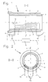
- the basic pipe 1 is one or more, in the present case two Heat exchanger 4 assigned.
- Each heat exchanger 4 is in a circulation system filled with a liquid or gaseous heat transfer medium of a heat pump 5 known per se and not described in detail by means of a so-called forward and return 6a; 6b integrated and expediently connected to the same via pipes 7, it being recommended to use glycol or a mixture of the same with water when using a liquid heat transfer medium to ensure frost protection.
- a heat pump 5 known per se and not described in detail by means of a so-called forward and return 6a; 6b integrated and expediently connected to the same via pipes 7, it being recommended to use glycol or a mixture of the same with water when using a liquid heat transfer medium to ensure frost protection.
- Other suitable antifreeze agents such as alcohol, are also conceivable.
- the heat exchangers 4 are designed as elongated and multi-curved structures in the form of tubes 8.
- a circular cross section of the same is not mandatory, but a tube-like, for example flattened cross section can also be regarded as particularly suitable and is also covered by the invention.
- heat exchangers 4 heat-conducting materials, such as copper, aluminum, steel sheet, if necessary Especially offer stainless steel, glass or plastics.
- the heat exchangers 4 are furthermore fixed, optionally detachable by means of mechanical connecting means known per se, such as screws, on the inner or outer contour of the main pipe 1, in the preferred embodiment preferably in and / or below the liquid level of the waste water. It goes without saying that in the case of thick-walled main pipes 1, the arrangement of the heat exchangers 4 on the inner contour is preferable to the outer contour in order to advantageously support the desired effect of the heat exchange from the waste water into the heat transfer medium of the heat exchangers 4.
- the heat exchangers 4 can also be embedded in the wall 2 of the basic pipe 1, or in recesses 9 thereof, and optionally sealed to the waste water by a plate-shaped seal 10 or completely integrated into the wall 2 of the basic pipe 1, For example, be poured into concrete or plastic pipes (not shown). From the above it has also become clear that the heat exchangers 4 can be in direct as well as indirect contact with the waste water.
- the heat exchangers 4 of the basic pipes 1 are via a forward and return 6a; 6b in the circulation system of the heat pump 5. This can take place during the assembly or during the laying of the basic line pipes 1 in such a way that forward and return 6a; 6b are designed in such a way that they are led through the wall 2 of the basic pipe 1 and by means of connecting means 11, which can be plug-in or screw connections known per se (not shown in more detail), are connected to the circulation system of a heat pump 5.
- feed and rewind 6a; 6b to connect a plurality of heat exchangers 4 of a main line pipe 1 or a plurality of coaxially arranged basic line pipes 1 to one another in series and to the circulation system of the heat pump 5.
- the connection can be carried out by means of screw or plug connections outside the wall 2 (FIG. 3), but also by means of adhesive connections, which is particularly suitable for plastic pipes.
- Other suitable connection options, such as. B. soldering are also covered by the invention.
- the connecting means 11 for the forward and return 6a; 6b designed as plug-in connections and firmly embedded in the end face area of the main line pipes 1 to be connected (FIG. 4).
- a sealing effect with regard to the circulatory system of the heat pump 5 can be achieved, for example, by a conical design of the plug connection or sealing rings known per se.
Landscapes
- Engineering & Computer Science (AREA)
- Physics & Mathematics (AREA)
- Thermal Sciences (AREA)
- Mechanical Engineering (AREA)
- General Engineering & Computer Science (AREA)
- Environmental & Geological Engineering (AREA)
- Health & Medical Sciences (AREA)
- Life Sciences & Earth Sciences (AREA)
- Hydrology & Water Resources (AREA)
- Public Health (AREA)
- Water Supply & Treatment (AREA)
- Heat-Exchange Devices With Radiators And Conduit Assemblies (AREA)
Applications Claiming Priority (2)
| Application Number | Priority Date | Filing Date | Title |
|---|---|---|---|
| DE10062337A DE10062337A1 (de) | 2000-12-14 | 2000-12-14 | Vorrichtung zum Entsorgen von Abwasser |
| DE10062337 | 2000-12-14 |
Publications (1)
| Publication Number | Publication Date |
|---|---|
| EP1215460A2 true EP1215460A2 (fr) | 2002-06-19 |
Family
ID=7667135
Family Applications (1)
| Application Number | Title | Priority Date | Filing Date |
|---|---|---|---|
| EP01129568A Withdrawn EP1215460A2 (fr) | 2000-12-14 | 2001-12-12 | Dispositif pour l'évacuation des eaux usées |
Country Status (2)
| Country | Link |
|---|---|
| EP (1) | EP1215460A2 (fr) |
| DE (1) | DE10062337A1 (fr) |
Cited By (14)
| Publication number | Priority date | Publication date | Assignee | Title |
|---|---|---|---|---|
| EP1591740A1 (fr) * | 2004-04-30 | 2005-11-02 | Urs Studer | Echangeur de chaleur et installation de récupération de la chaleur des eaux usées |
| WO2006056544A1 (fr) * | 2004-11-22 | 2006-06-01 | Joachim Schulte | Absorbeur pour structure de tuyaux ou de canaux et structure de tuyaux ou de canaux muni d'un tel absorbeur |
| ES2284359A1 (es) * | 2005-11-11 | 2007-11-01 | Francisco De Vicente Jimenez | Dispositivo para la recuperacion de parte de la energia residual de los vertidos de agua sanitaria. |
| EP1939572A1 (fr) * | 2006-12-27 | 2008-07-02 | General Electric Company | Système échangeur de chaleur doté de collecteurs structurellement intégrés avec un conduit |
| WO2010031193A1 (fr) * | 2008-09-16 | 2010-03-25 | Rabtherm Ag | Installation pour extraire de la chaleur d'eau courante |
| CN1891916B (zh) * | 2005-07-04 | 2010-11-03 | 大连葆光节能空调设备厂 | 一种生态小区的水循环利用系统 |
| FR2954819A1 (fr) * | 2009-12-30 | 2011-07-01 | Lyonnaise Eaux France | Dispositif pour extraire de la chaleur dans un collecteur d'eaux usees, et installation mettant en oeuvre de tels dispositifs. |
| FR2959300A1 (fr) * | 2010-04-21 | 2011-10-28 | Lyonnaise Eaux France | Procede pour extraire de la chaleur d'un effluent circulant dans une conduite, echangeur de chaleur et installation mettant en oeuvre un tel procede. |
| FR2959301A1 (fr) * | 2010-04-21 | 2011-10-28 | Lyonnaise Eaux France | Installation pour extraire de la chaleur d'un effluent circulant dans une conduite, et echangeur de chaleur pour une telle installation. |
| WO2011138011A3 (fr) * | 2010-05-07 | 2012-02-23 | Uhrig Kanaltechnik Gmbh | Dispositif d'échange thermique, utilisation et ensemble d'échange thermique |
| WO2013005161A1 (fr) | 2011-07-06 | 2013-01-10 | Lyonnaise Des Eaux France | Procédé pour extraire de la chaleur d'un effluent circulant dans une conduite, en particulier d'eaux usées, échangeur de chaleur et matériau pour mettre en oeuvre ce procédé |
| JP2013040469A (ja) * | 2011-08-12 | 2013-02-28 | Toa Grout Kogyo Co Ltd | 管路構造及び施工方法並びにスリーブ及び製造方法 |
| JP2015086625A (ja) * | 2013-10-31 | 2015-05-07 | 株式会社興和 | 採熱構造体,流体熱利用装置及び流体通過体の改修方法 |
| CN115388677A (zh) * | 2022-08-29 | 2022-11-25 | 重庆钢铁股份有限公司 | 废水热量回收装置 |
Families Citing this family (4)
| Publication number | Priority date | Publication date | Assignee | Title |
|---|---|---|---|---|
| DE102006008379B4 (de) * | 2006-02-21 | 2011-03-31 | Henze, Michael, Dipl.-Ing. | Rohrsystem zur Abwasserentsorgung und Wärmerückgewinnung |
| DE102010019728B4 (de) * | 2010-05-07 | 2013-06-27 | Uhrig Kanaltechnik Gmbh | Wärmetauschervorrichtung, Verwendung, Wärmetauscheranordnung |
| DE102010026146A1 (de) * | 2010-07-05 | 2012-01-05 | Brandenburger Patentverwertung Gdbr. | Anordnung zur Rückgewinnung von Wärmeenergie aus Abwasser in einem Abwasserkanal sowie Verfahren zur Montage einer solchen Anordnung |
| DE202012100798U1 (de) * | 2012-03-07 | 2013-06-11 | Joachim Schulte | Wärmerückgewinnungssystem |
Citations (3)
| Publication number | Priority date | Publication date | Assignee | Title |
|---|---|---|---|---|
| DE19723148A1 (de) | 1997-06-03 | 1998-12-10 | Markus Dr Med Daschner | Vorrichtung zur Wärmerückgewinnung aus Abwasser |
| DE19817031A1 (de) | 1998-04-17 | 1999-10-21 | Markus Daschner | Wartungsfreie Vorrichtung zur Wärmerückgewinnung aus Abwasser |
| DE19906999A1 (de) | 1999-02-18 | 2000-08-31 | Biolog Biotechnologie Und Logi | Vorrichtung zur Wärmerückgewinnung aus Abwasser |
Family Cites Families (1)
| Publication number | Priority date | Publication date | Assignee | Title |
|---|---|---|---|---|
| DE4202791A1 (de) * | 1991-05-11 | 1992-11-12 | Linder Rudolf Fa | Waermetauscher fuer abwasser fuehrende rohr- oder schlauchleitungen |
-
2000
- 2000-12-14 DE DE10062337A patent/DE10062337A1/de not_active Ceased
-
2001
- 2001-12-12 EP EP01129568A patent/EP1215460A2/fr not_active Withdrawn
Patent Citations (3)
| Publication number | Priority date | Publication date | Assignee | Title |
|---|---|---|---|---|
| DE19723148A1 (de) | 1997-06-03 | 1998-12-10 | Markus Dr Med Daschner | Vorrichtung zur Wärmerückgewinnung aus Abwasser |
| DE19817031A1 (de) | 1998-04-17 | 1999-10-21 | Markus Daschner | Wartungsfreie Vorrichtung zur Wärmerückgewinnung aus Abwasser |
| DE19906999A1 (de) | 1999-02-18 | 2000-08-31 | Biolog Biotechnologie Und Logi | Vorrichtung zur Wärmerückgewinnung aus Abwasser |
Cited By (35)
| Publication number | Priority date | Publication date | Assignee | Title |
|---|---|---|---|---|
| WO2005106371A1 (fr) * | 2004-04-30 | 2005-11-10 | Ligrufa Ag | Echangeur thermique et dispositif destine a extraire de la chaleur a partir d'eaux usees |
| JP4871858B2 (ja) * | 2004-04-30 | 2012-02-08 | リヨネーズ デ ゾ | 廃水から熱を抽出するための熱交換器および設備 |
| JP2007535651A (ja) * | 2004-04-30 | 2007-12-06 | リグルファ・アクチェンゲゼルシャフト | 廃水から熱を抽出するための熱交換器および設備 |
| US8720533B2 (en) | 2004-04-30 | 2014-05-13 | Lyonnaise Des Eaux | Heat exchanger and installation for extracting heat from waste water |
| EP1591740A1 (fr) * | 2004-04-30 | 2005-11-02 | Urs Studer | Echangeur de chaleur et installation de récupération de la chaleur des eaux usées |
| CN101002065B (zh) * | 2004-04-30 | 2011-04-13 | 里昂水务公司 | 用于从废水中回收热量的热交换器和装置 |
| JP4938681B2 (ja) * | 2004-11-22 | 2012-05-23 | シュルテ ヨアヒム | 管構造物または通路構造物に用いられる吸収器ならびにこのような吸収器を備えた管構造物または通路構造物 |
| WO2006056544A1 (fr) * | 2004-11-22 | 2006-06-01 | Joachim Schulte | Absorbeur pour structure de tuyaux ou de canaux et structure de tuyaux ou de canaux muni d'un tel absorbeur |
| JP2008520953A (ja) * | 2004-11-22 | 2008-06-19 | シュルテ ヨアヒム | 管構造物または通路構造物に用いられる吸収器ならびにこのような吸収器を備えた管構造物または通路構造物 |
| US7637286B2 (en) | 2004-11-22 | 2009-12-29 | Joachim Schulte | Absorber for a pipe construction or sewer construction and pipe or sewer configuration provided with the absorber |
| CN1891916B (zh) * | 2005-07-04 | 2010-11-03 | 大连葆光节能空调设备厂 | 一种生态小区的水循环利用系统 |
| ES2284359B1 (es) * | 2005-11-11 | 2008-07-01 | Francisco De Vicente Jimenez | Dispositivo para la recuperacion de parte de la energia residual de los vertidos de agua sanitaria. |
| ES2284359A1 (es) * | 2005-11-11 | 2007-11-01 | Francisco De Vicente Jimenez | Dispositivo para la recuperacion de parte de la energia residual de los vertidos de agua sanitaria. |
| US7784528B2 (en) | 2006-12-27 | 2010-08-31 | General Electric Company | Heat exchanger system having manifolds structurally integrated with a duct |
| JP2008164276A (ja) * | 2006-12-27 | 2008-07-17 | General Electric Co <Ge> | 導管と一体構造のマニホルドを有する熱交換器システム |
| EP1939572A1 (fr) * | 2006-12-27 | 2008-07-02 | General Electric Company | Système échangeur de chaleur doté de collecteurs structurellement intégrés avec un conduit |
| WO2010031193A1 (fr) * | 2008-09-16 | 2010-03-25 | Rabtherm Ag | Installation pour extraire de la chaleur d'eau courante |
| FR2954819A1 (fr) * | 2009-12-30 | 2011-07-01 | Lyonnaise Eaux France | Dispositif pour extraire de la chaleur dans un collecteur d'eaux usees, et installation mettant en oeuvre de tels dispositifs. |
| WO2011080687A3 (fr) * | 2009-12-30 | 2011-08-25 | Lyonnaise Des Eaux France | Dispositif pour extraire de la chaleur dans un collecteur d'eaux usees, et installation mettant en oeuvre de tels dispositifs |
| FR2959300A1 (fr) * | 2010-04-21 | 2011-10-28 | Lyonnaise Eaux France | Procede pour extraire de la chaleur d'un effluent circulant dans une conduite, echangeur de chaleur et installation mettant en oeuvre un tel procede. |
| FR2959301A1 (fr) * | 2010-04-21 | 2011-10-28 | Lyonnaise Eaux France | Installation pour extraire de la chaleur d'un effluent circulant dans une conduite, et echangeur de chaleur pour une telle installation. |
| WO2011132158A3 (fr) * | 2010-04-21 | 2012-07-26 | Lyonnaise Des Eaux France | Installation pour extraire de la chaleur d ' un effluent circulant dans une conduite |
| WO2011132156A3 (fr) * | 2010-04-21 | 2012-09-07 | Lyonnaise Des Eaux France | Procédé pour extraire de la chaleur d'un effluent circulant dans une conduite, échangeur de chaleur et installation mettant en oeuvre un tel procédé |
| CN102884390B (zh) * | 2010-04-21 | 2015-04-22 | 里昂水务法国公司 | 从管道中流动的废液提取热量的方法、使用该方法的热交换器及设备 |
| CN102884389B (zh) * | 2010-04-21 | 2015-01-21 | 里昂水务法国公司 | 从管道中流动的废液提取热量的设备及设备用的热交换器 |
| CN102884389A (zh) * | 2010-04-21 | 2013-01-16 | 里昂水务法国公司 | 从管道中流动的废液提取热量的设备及设备用的热交换器 |
| CN102884390A (zh) * | 2010-04-21 | 2013-01-16 | 里昂水务法国公司 | 从管道中流动的废液提取热量的方法、使用该方法的热交换器及设备 |
| WO2011138011A3 (fr) * | 2010-05-07 | 2012-02-23 | Uhrig Kanaltechnik Gmbh | Dispositif d'échange thermique, utilisation et ensemble d'échange thermique |
| CN103688124A (zh) * | 2011-07-06 | 2014-03-26 | 里昂水务法国公司 | 从管道中流动的流出物特别是废水中提取热量的方法、以及实施该方法的热交换器和材料 |
| US20140151005A1 (en) * | 2011-07-06 | 2014-06-05 | Lyonnaise Des Eaux France | Method for extraction heat from an effluent, especially waste water, circulating in a conduit, heat exchanger and material for implementing said method |
| FR2977659A1 (fr) * | 2011-07-06 | 2013-01-11 | Lyonnaise Eaux France | Procede pour extraire de la chaleur d'un effluent circulant dans une conduite, en particulier d'eaux usees, echangeur de chaleur et materiau pour mettre en oeuvre ce procede |
| WO2013005161A1 (fr) | 2011-07-06 | 2013-01-10 | Lyonnaise Des Eaux France | Procédé pour extraire de la chaleur d'un effluent circulant dans une conduite, en particulier d'eaux usées, échangeur de chaleur et matériau pour mettre en oeuvre ce procédé |
| JP2013040469A (ja) * | 2011-08-12 | 2013-02-28 | Toa Grout Kogyo Co Ltd | 管路構造及び施工方法並びにスリーブ及び製造方法 |
| JP2015086625A (ja) * | 2013-10-31 | 2015-05-07 | 株式会社興和 | 採熱構造体,流体熱利用装置及び流体通過体の改修方法 |
| CN115388677A (zh) * | 2022-08-29 | 2022-11-25 | 重庆钢铁股份有限公司 | 废水热量回收装置 |
Also Published As
| Publication number | Publication date |
|---|---|
| DE10062337A1 (de) | 2002-07-04 |
Similar Documents
| Publication | Publication Date | Title |
|---|---|---|
| EP1215460A2 (fr) | Dispositif pour l'évacuation des eaux usées | |
| DE19719311C2 (de) | Wärmetauscher | |
| EP1815073B1 (fr) | Absorbeur pour structure de tuyaux ou de canaux et structure de tuyaux ou de canaux muni d'un tel absorbeur | |
| DE102012105539A1 (de) | Wärmenutzungsanlage | |
| DE20203712U1 (de) | Vorrichtung zur Gewinnung von Wärmeenergie mit einer Wärmepumpe | |
| DE102010007726A1 (de) | Wärmetauscheranordnung | |
| WO2022008415A1 (fr) | Procédé et système de refroidissement ou de chauffage d'eaux usées | |
| EP3914872B1 (fr) | Module d'échangeur thermique, système d'échangeur thermique et procédé de fabrication du système d'échangeur thermique | |
| WO2010111998A2 (fr) | Conduite d'eaux usées comportant un dispositif de guidage d'eau fraîche et échangeur de chaleur | |
| EP2020576A2 (fr) | Collecteur solaire destiné au réchauffement d'un liquide | |
| DE2940299A1 (de) | Waermetauscher | |
| DE2641119B2 (de) | Vorrichtung zum Erwärmen von Flüssigkeiten durch Sonnenenergie | |
| DE1601154A1 (de) | Vorrichtung an Rohrwaermeaustauschern mit plattenfoermigen Rohren | |
| CH699393B1 (de) | Wärmetauscher für den Rauchgaskanal einer Feuerung. | |
| DE3045740A1 (de) | Vorrichtung zum rueckgewinnen von waerme an einem geruchsverschluss einer abwasserleitung | |
| DE8203297U1 (de) | Geruchsverschluss | |
| EP4242531B1 (fr) | Dispositif antigel pour dispositif d'alimentation en eau dans un véhicule de loisir | |
| DE3137146A1 (de) | "kessel zur erzeugung und speicherung von heissem wasser" | |
| DE102007031084A1 (de) | Abwasserrohr mit Wärmetauscherelement | |
| DE2609374C3 (de) | Einsteckteil | |
| DE3545423A1 (de) | Abfluss-leitungsabschnitt mit einem waermetauscher | |
| DE3119855A1 (de) | Waermetauscher zur rueckgewinnung von abwaerme | |
| DE102010015851A1 (de) | Solarheizung | |
| DE202008017556U1 (de) | Anlage zur Umwelt-Wärmenutzung | |
| DE102004024794B4 (de) | Wärmetauschervorrichtung |
Legal Events
| Date | Code | Title | Description |
|---|---|---|---|
| PUAI | Public reference made under article 153(3) epc to a published international application that has entered the european phase |
Free format text: ORIGINAL CODE: 0009012 |
|
| AK | Designated contracting states |
Kind code of ref document: A2 Designated state(s): AT BE CH CY DE DK ES FI FR GB GR IE IT LI LU MC NL PT SE TR |
|
| AX | Request for extension of the european patent |
Free format text: AL;LT;LV;MK;RO;SI |
|
| STAA | Information on the status of an ep patent application or granted ep patent |
Free format text: STATUS: THE APPLICATION IS DEEMED TO BE WITHDRAWN |
|
| 18D | Application deemed to be withdrawn |
Effective date: 20040701 |