EP1215543B1 - Appareil de fixation - Google Patents
Appareil de fixation Download PDFInfo
- Publication number
- EP1215543B1 EP1215543B1 EP01129961A EP01129961A EP1215543B1 EP 1215543 B1 EP1215543 B1 EP 1215543B1 EP 01129961 A EP01129961 A EP 01129961A EP 01129961 A EP01129961 A EP 01129961A EP 1215543 B1 EP1215543 B1 EP 1215543B1
- Authority
- EP
- European Patent Office
- Prior art keywords
- oil
- roller
- releasing agent
- fixing
- heat
- Prior art date
- Legal status (The legal status is an assumption and is not a legal conclusion. Google has not performed a legal analysis and makes no representation as to the accuracy of the status listed.)
- Expired - Lifetime
Links
- 230000003578 releasing effect Effects 0.000 claims description 35
- 239000000463 material Substances 0.000 claims description 9
- 238000010438 heat treatment Methods 0.000 claims description 8
- 229920002545 silicone oil Polymers 0.000 claims description 8
- 239000011347 resin Substances 0.000 claims description 6
- 229920005989 resin Polymers 0.000 claims description 6
- 238000009413 insulation Methods 0.000 claims description 5
- 230000005855 radiation Effects 0.000 claims description 3
- 239000003795 chemical substances by application Substances 0.000 description 16
- 239000007788 liquid Substances 0.000 description 15
- 238000010276 construction Methods 0.000 description 13
- 230000005540 biological transmission Effects 0.000 description 8
- 229910052736 halogen Inorganic materials 0.000 description 7
- 150000002367 halogens Chemical class 0.000 description 7
- 238000000034 method Methods 0.000 description 6
- 230000007246 mechanism Effects 0.000 description 5
- 229910052751 metal Inorganic materials 0.000 description 5
- 239000002184 metal Substances 0.000 description 5
- 230000001105 regulatory effect Effects 0.000 description 5
- 229910052782 aluminium Inorganic materials 0.000 description 3
- XAGFODPZIPBFFR-UHFFFAOYSA-N aluminium Chemical compound [Al] XAGFODPZIPBFFR-UHFFFAOYSA-N 0.000 description 3
- 230000006870 function Effects 0.000 description 3
- 230000009467 reduction Effects 0.000 description 3
- 229920002379 silicone rubber Polymers 0.000 description 3
- 239000004945 silicone rubber Substances 0.000 description 3
- RYGMFSIKBFXOCR-UHFFFAOYSA-N Copper Chemical compound [Cu] RYGMFSIKBFXOCR-UHFFFAOYSA-N 0.000 description 2
- 229910052802 copper Inorganic materials 0.000 description 2
- 239000010949 copper Substances 0.000 description 2
- 229920001973 fluoroelastomer Polymers 0.000 description 2
- 230000004048 modification Effects 0.000 description 2
- 238000012986 modification Methods 0.000 description 2
- 230000003287 optical effect Effects 0.000 description 2
- 239000002344 surface layer Substances 0.000 description 2
- 239000004809 Teflon Substances 0.000 description 1
- 229920006362 Teflon® Polymers 0.000 description 1
- 230000015572 biosynthetic process Effects 0.000 description 1
- 239000011248 coating agent Substances 0.000 description 1
- 238000000576 coating method Methods 0.000 description 1
- 230000001276 controlling effect Effects 0.000 description 1
- 230000008878 coupling Effects 0.000 description 1
- 238000010168 coupling process Methods 0.000 description 1
- 238000005859 coupling reaction Methods 0.000 description 1
- 238000010586 diagram Methods 0.000 description 1
- 230000002349 favourable effect Effects 0.000 description 1
- 238000012840 feeding operation Methods 0.000 description 1
- 239000011521 glass Substances 0.000 description 1
- 230000006698 induction Effects 0.000 description 1
- 239000010410 layer Substances 0.000 description 1
- 239000000155 melt Substances 0.000 description 1
- 230000008569 process Effects 0.000 description 1
Images

Classifications
-
- G—PHYSICS
- G03—PHOTOGRAPHY; CINEMATOGRAPHY; ANALOGOUS TECHNIQUES USING WAVES OTHER THAN OPTICAL WAVES; ELECTROGRAPHY; HOLOGRAPHY
- G03G—ELECTROGRAPHY; ELECTROPHOTOGRAPHY; MAGNETOGRAPHY
- G03G15/00—Apparatus for electrographic processes using a charge pattern
- G03G15/20—Apparatus for electrographic processes using a charge pattern for fixing, e.g. by using heat
- G03G15/2003—Apparatus for electrographic processes using a charge pattern for fixing, e.g. by using heat using heat
- G03G15/2014—Apparatus for electrographic processes using a charge pattern for fixing, e.g. by using heat using heat using contact heat
- G03G15/2017—Structural details of the fixing unit in general, e.g. cooling means, heat shielding means
- G03G15/2025—Structural details of the fixing unit in general, e.g. cooling means, heat shielding means with special means for lubricating and/or cleaning the fixing unit, e.g. applying offset preventing fluid
-
- G—PHYSICS
- G03—PHOTOGRAPHY; CINEMATOGRAPHY; ANALOGOUS TECHNIQUES USING WAVES OTHER THAN OPTICAL WAVES; ELECTROGRAPHY; HOLOGRAPHY
- G03G—ELECTROGRAPHY; ELECTROPHOTOGRAPHY; MAGNETOGRAPHY
- G03G2215/00—Apparatus for electrophotographic processes
- G03G2215/20—Details of the fixing device or porcess
- G03G2215/2093—Release agent handling devices
Definitions
- the present invention relates to a fixing apparatus that is suitably used for an image forming apparatus employing an electrophotographic method or an electrostatic recording method and fixes an unfixed image. More particularly, the present invention relates to a fixing apparatus including a releasing liquid applying mechanism.
- a fixing apparatus for applying a releasing agent such as silicone oil
- a fixing roller As a fixing apparatus for applying a releasing agent (hereinafter referred to as the "oil"), such as silicone oil, to a fixing roller, there have conventionally been proposed an apparatus that applies the oil to the fixing roller using felt, an apparatus that draws up the oil using felt and applying the drawn-up oil to the fixing roller through an applying roller, an apparatus that draws up the silicone oil using a draw-up roller, and the like.
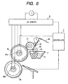
- Fig. 6 attached hereto shows the fixing apparatus that draws up the silicone oil using the draw-up roller.
- symbol P represents an oil pan P as a releasing agent containing means for silicone oil O.
- a first draw-up roller 43 as a releasing agent drawing-up means is partially immersed in the oil O in the oil pan P, and a second draw-up roller 42 as a releasing agent drawing-up means rotates while contacting the first draw-up roller 43 or with a gap therebetween.
- the first and second draw-up rollers 42 and 43 are rotatively driven by a driving source (not shown).
- an applying roller 41 as a releasing agent applying means which is rotatively driven by a driving source (not shown), rotates in contact with the second draw-up roller 42.
- the applying roller 41 is freely switched between a position in which the applying roller 41 contacts a fixing roller 4a and a position in which the applying roller 41 is separated from the fixing roller 4a.
- the applying roller 41 is provided so as to contact the fixing roller 4a at all times. With this construction, the drawn-up oil O is applied to the surface of the fixing roller 4a.
- reference numeral 4b denotes a pressurizing roller that rotates in pressure contact with the fixing roller 4a.
- a nip portion between these rollers 4a and 4b heated by halogen heaters 45a and 45b fixes an image by transporting a recording material with pressure thereon.
- the halogen heaters 45a and 45b are respectively disposed at the centers of the rollers 4a and 4b.
- a metering blade 44 as a releasing agent regulating means contacts the applying roller 41.
- the metering blade 44 is biased by a spring 49 so that the metering blade 44 is pressed against the applying roller 41 with constant pressure at all times.
- the metering blade 44 is made of an elastic body, such as fluororubber. With this construction, the amount of oil on the applying roller 41 is regulated to a predetermined value.
- the temperature of the releasing agent is lower than that of the fixing roller, so that when the releasing agent is applied onto the fixing roller, the applied releasing agent deprives heat from the surface of the fixing roller.
- the fixability is lowered.
- the temperature of the releasing agent is close to room temperature, which leads to the lowest fixability and may cause fixing failures.
- the surface of the fixing roller is formed by coating the surface of a metal core with silicone rubber or fluororubber.
- a fixing roller that is provided with a Teflon coat due to releasing property. This means that the fixing roller basically has a low heat conduction.
- Document US 4045165 discloses a contact heat fixing device which comprises a driving heated roller having a heating mechanism disposed in the interior thereof and a surface coated with an offset preventing material, a press roller which is rotated in intimate contact under pressure with said heat roller, a vessel for containing therein an offset preventing liquid and a feed mechanism for supplying the offset preventing liquid to the heated roller from the vessel, fixation of a toner image being accomplished by the passage of a support having the toner image thereon through the nip position of the heated roller and the press roller, wherein said feed mechanism includes an applicator for applying the offset preventing liquid to the surface of the heated roller and supply means for supplying the offset preventing liquid from the vessel to the applicator, said applicator being arranged so that it can shift between a position where it has a pressing contact with said supply means and a position where it has a pressing contact with said heated roller, in such a manner that the offset preventing liquid is supplied to said applicator when it is at said position, the applicator is moved from
- a fixing apparatus that prevents variations of glossiness during a successive fixing operation is provided.
- a fixing apparatus comprising a fixing rotary body for fixing an unfixed image on a supporting material, an applying member for applying a releasing liquid onto said fixing rotary body, a containing means for containing the releasing liquid and a supplying member contacting the releasing liquid in the containing means for supplying the releasing liquid to said applying member, wherein the containing means includes an outer vessel and an inner vessel for isolating said supplying member from said outer vessel is provided.
- the present invention will be described below by taking, as an example, a case where a copying machine employing an electrophotographic method is used.
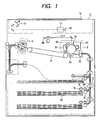
- Fig. 1 is a cross sectional view showing the schematic construction of the copying machine according to the present embodiment.
- a reader unit 1 including a scanning optical system reads image information.
- the image information is photoelectrically converted and is transferred to an image forming unit 2.
- an image is formed on a sheet fed by a sheet feeding unit 3.
- the sheet on which the image has been formed is transported to a fixing apparatus 4 and heat and pressure are applied thereto to fix a transferred image.
- a series of operations performed during an electrophotographic process is known and therefore is not described in detail here.
- a document placed on a document-supporting glass 1a is irradiated with light by a scanning optical system 1b having a light source and a group of reflection mirrors, and reflected light is imaged on a CCD 1d through a reduction lens 1c and is photoelectrically converted. After being A/D converted, this image information is transferred to a memory.
- the maximum document size is LTR or A3.
- a sheet feeding cassette 3a that carries and contains sheets is detachably provided in the lower portion of the copying machine.
- a solenoid (not shown) coupled to a pickup roller 3c is turned on during standby, so that the pickup roller 3c is separated from a surface of the sheets.
- the solenoid when feeding a sheet, the solenoid is turned off, so that the pickup roller 3c is brought into contact with the sheet surface. Then, the first sheet is fed by the pickup roller 3c that receives a rotational driving force.
- the driving force for the pickup roller 3c is transmitted from a transport roller 3e through a timing belt 3t.
- the picked-up sheet is transported while being pinched between the transport roller 3e and a retard roller 3f.
- the transport roller 3e receives a rotational driving force in a direction in which the sheet is to be transported, while the retard roller 3f is rotatively driven through a torque limiter (not shown) in a direction opposite to the transport direction. Accordingly, only the front end of the first sheet exists between these rollers. Therefore, the torque limiter gives in to the friction force between the sheet and the roller and the retard roller 3f rotates in the transport direction. Next, if several overlapping sheets reach the pinching portion between these rollers, the friction force between the first and second sheets gives in to the torque limiter and therefore the retard roller 3f is rotated in a direction opposite to the transport direction. As a result, only the uppermost sheet is separated and fed in advance. Even if a plurality of sheets are picked up at the same time, only the uppermost sheet is separated and fed in advance by the same operation.
- the sheet feeding operation described above makes it possible to feed the carried sheets one by one.
- the sheet fed by the sheet feeding unit 3 is temporarily stopped at the front end thereof by the resist roller 22 and is fed again in accordance with the image formed by the image forming unit 2.
- the image is transferred in a transferring unit.
- the resist roller 22 is rotatively driven by coupling a clutch (not shown) under the control by a controller of a main body.
- a laser light emitting unit 2a emits laser light under the control by a laser driver in accordance with image information read by the reader unit 1. Then, the emitted laser light is scanned in the generating line direction of a photosensitive drum 2c by the rotation of a polygon mirror 2b, and a latent image is formed on the surface of the drum that has been charged in advance by a charger 2d. This latent image is developed by a developer 2e provided around the photosensitive drum 2c, and a toner image is transferred by a transfer charger 2g onto a sheet transported by a pair of pre-transfer rollers 2f. After this image transfer operation, residual toner on the drum surface is removed by a cleaner 2h.
- the sheet S onto which the toner image has been transferred in the image forming unit 2 is introduced into a fixing apparatus 4 by a transport belt 8.
- a fixing roller 4a and a pressurizing roller 4b When passing between a fixing roller 4a and a pressurizing roller 4b, the sheet is given heat and pressure. As a result, the toner image melts and adheres to the sheet.
- Fig. 2 shows the construction of the main part of the fixing apparatus according to the first embodiment of the present invention.
- each of the fixing roller 4a and the pressurizing roller 4b is formed by having silicone rubber fixed onto the upper surface of a metal core made of aluminum.
- Halogen heaters 45a and 45b that are heat sources are respectively disposed inside the metal cores.
- Thermistors 46 and 47 that contact surface layers made of the silicone rubber detect the temperatures of the surface layers, respectively.
- a controller C of the main body compares the temperature detected by each thermistor with a preset temperature. If the detected temperature is lower than the preset temperature, each of the halogen heaters 45a and 45b is turned on through an AC driver D. On the other hand, if the detected temperature is higher than the preset temperature, each of the halogen heaters 45a and 45b is turned off. By controlling the halogen heaters 45a and 45b in this manner, the temperatures of the fixing roller 4a and the pressurizing roller 4b are kept constant.
- Symbol O denotes silicone oil as a releasing agent
- symbol P an oil pan as the outer vessel of a releasing agent containing means for containing the silicone oil O
- reference numeral 43 the first draw-up roller
- numeral 42 the second draw-up roller
- numeral 41 an applying roller.
- a gear 41g receives a rotational driving force from a driving force input means (not shown).
- the driving force is transmitted to gears 42g and 43g in succession and each of the rollers 41, 42, and 43 is rotated in each corresponding arrow direction.
- rollers 41, 42, and 43 are rotatively supported by the same supporting plates 56a and 56b.
- bearings and the like are omitted in this embodiment.
- these rollers may be supported using slide bearings or other bearings.
- the oil O drawn up by the first draw-up roller 43 is regulated by the gap portion between the first draw-up roller 43 and the second draw-up roller 42, so that the amount of oil passing through the gap portion is regulated to some extent.
- the amount of passing oil is determined by the gap and the silicone oil O passing through this gap is drawn up to the nip portion between the applying roller 41 and the second draw-up roller 42.
- the oil O passing through the nip portion with the applying roller 41 is conveyed by the outer surface of the applying roller 41 to a metering blade 44 as a releasing agent applying means.
- the metering blade 44 is capable of rotating about a rotational center axis 44c and is biased against the applying roller 41 with constant pressure by a blade biasing string 49.
- the amount of passing oil is regulated to a desired constant volume.
- the thickness of the oil film has an optimum amount.
- the oil pan P is made of a resin having excellent heat insulation property and prevents heat radiation from the oil pan P.
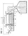
- Fig. 3 is a diagram of the oil pan P viewed from a side thereof.
- a float 50 floats in the oil O in the oil pan P.
- the float 50 is supported by a lever that is capable of rotating about an axis 51, and is raised and lowered in accordance with the liquid level of the oil O. Also, a flag 52 disposed on a side opposite to the float 50 is also rotated at the same time.
- the controller C of the main body detects a signal showing this situation and activates an oil suction pump 54.
- the oil suction pump 54 pumps the oil from an oil tank 55 disposed in a lower portion, thereby supplying the oil to the oil pan P.
- a surrounding member 48 that functions as an inner oil pan is provided inside the oil pan P as an outer oil pan, with the first draw-up roller 43 being surrounded by the surrounding member 48.
- the oil in the oil pan P is divided by this surrounding member 48 into oil in the inner oil pan and oil in the outer oil pan.
- the area of the opening portion 48h is small so that it is impossible for the oil O to freely come and go between the inner oil pan and the outer oil pan.
- the oil O enters from the outer oil pan to the inner oil pan to compensate for the amount of oil O drawn up by the first draw-up roller 43, thereby obtaining constant liquid levels of the oil in the inner oil pan and the outer oil pan.
- the surrounding member 48 that functions as the inner oil pan is made of a resin having excellent heat insulation property and prevents heat radiation to the oil O1 in the outer oil pan. This construction makes it unnecessary to heat all of the oil O in both of the outer oil pan P and the surrounding member 48 as the inner oil pan, when an apparatus is activated. That is, it is enough to heat only the oil O2 in the surrounding member 48 as the inner oil pan. This achieves reduction of a warm-up time.
- a heat source for heating the oil O is the fixing roller 4a. Heat is transmitted from the fixing roller 4a to the applying roller 41, the second draw-up roller 42, and then the first draw-up roller 43, and finally reaches the oil O in the oil pan P.
- a portion for drawing up the oil from the aforementioned oil tank 55 is provided at the end portion outside of the surrounding member 48 and the opening portion of the surrounding member 48 as the inner oil pan exists in the center portion. Therefore, newly drawn-up oil whose temperature is low is not directly drawn up but enters into the inside of the surrounding member 48 after being heated to some extent.
- the surrounding member 48o may be modified as follows.
- the inside of the surrounding member 48o is formed using a metal 48i having a high heat conductivity such as aluminum or copper, and a resin having heat insulation property is fixed to the outside of the surrounding member 48o.
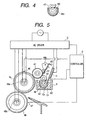
- Fig. 5 shows another embodiment.
- This embodiment relates to an example in which the fixability is further improved by providing a heat source that is used specifically to heat the oil O.
- a heat transmission unit 61 is provided on a side surface of the surrounding member 48 as the inner oil pan in the longitudinal direction, with the heat transmission unit 61 extending upward from an opening end.
- the heat transmission unit 61 is formed using a metal plate having a high heat conduction, such as aluminum or copper.
- a sheet-like heater H is fixed to the outer surface of the heat transmission unit 61. Heat generated by the sheet-like heater H is transmitted to the entire surrounding member via the heat transmission unit 61, thereby heating the oil.
- a thermistor 62 for detecting the temperature of the oil is disposed inside the outer oil pan P.
- the controller C detects the oil temperature and controls the ON/OFF of current-passage for the sheet-like heater H via the AC driver D so that the oil temperature is kept constant with respect to a set temperature.
- the heat transmission plate 61 is disposed so as to surround the first draw-up roller 43 and to divide the oil in the oil pan P into oil in the inner oil pan and oil in the outer oil pan. Also, like in the previous embodiment, an opening portion is provided at the center so that the oil in the inner oil pan communicates with the oil in the outer oil pan through the opening portion.
- the surrounding member 48 having the heat transmission unit 61 for transmitting heat to the oil O surrounds the first draw-up roller 43.
- the amount of oil that needs to be heated is reduced and therefore it becomes possible to shorten a warm-up time.
- the temperature of the oil O is adjusted in the manner described above, so that it is possible to prevent the unevenness and variations of glossiness.
- a resin having excellent heat insulation property may be fixed to the outside of the surrounding member having the heat transmission unit 61. This construction prevents heat from escaping to the outer portion O1 that does not contribute to the drawing-up of the oil.
- the thermistor for detecting the oil temperature may be disposed inside the inner portion O2.
- a sheet-like heating element is used as a heater unit.
- another heat source such as a halogen heater or a heating element employing an induction heating method, may be used in a similar manner.
Landscapes
- Physics & Mathematics (AREA)
- General Physics & Mathematics (AREA)
- Fixing For Electrophotography (AREA)
Claims (7)
- Appareil de fixage comportant :un corps rotatif (4a) de fixage destiné à fixer par chauffage une image non fixée formée sur un support d'enregistrement (S) ;un moyen d'application (41) destiné à appliquer l'agent anti-adhérent (O) sur ledit corps rotatif (4a) de fixage ;un récipient extérieur (P) destiné à emmagasiner un agent anti-adhérent (O) ;un récipient intérieur (48) ayant une excellente propriété d'isolation thermique empêchant un rayonnement thermique vers l'agent anti-adhérent (O) dans le récipient extérieur (P), l'agent anti-adhérent se trouvant dans ledit récipient intérieur (48) communiquant avec l'agent anti-adhérent se trouvant dans ledit récipient extérieur (P) ; etun moyen d'alimentation (43) en contact avec l'agent anti-adhérent (O) pour amener l'agent anti-adhérent dudit récipient intérieur (48) audit moyen d'application (41).
- Appareil de fixage selon la revendication 1, comportant une source de chaleur (4a) destinée à chauffer l'agent anti-adhérent (O) dans ledit récipient intérieur (48).
- Appareil de fixage selon la revendication 2, comportant :un moyen de détection (62) destiné à détecter la température de l'agent anti-adhérent (O) ; etun moyen de commande (C) destiné à commander un courant fourni audit moyen de chauffage (4a) en fonction de la température de l'agent anti-adhérent (O) détectée par ledit moyen de détection (62).
- Appareil de fixage selon les revendications 1 à 3, dans lequel ledit récipient intérieur (48) comprend une couche de résine d'isolation thermique.
- Appareil de fixage selon la revendication 4, dans lequel ledit récipient intérieur (48) comprend une couche à haute conduction de la chaleur située sur une surface intérieure de la couche de résine d'isolation thermique.
- Appareil de fixage selon les revendications 1 à 5, comportant une pompe (54) d'aspiration d'huile destinée à amener un agent anti-adhérent (O) audit récipient extérieur (P).
- Appareil de fixage selon les revendications 1 à 6, dans lequel l'agent anti-adhérent est une huile de silicone.
Applications Claiming Priority (2)
| Application Number | Priority Date | Filing Date | Title |
|---|---|---|---|
| JP2000384002 | 2000-12-18 | ||
| JP2000384002A JP3619152B2 (ja) | 2000-12-18 | 2000-12-18 | 定着装置 |
Publications (3)
| Publication Number | Publication Date |
|---|---|
| EP1215543A2 EP1215543A2 (fr) | 2002-06-19 |
| EP1215543A3 EP1215543A3 (fr) | 2004-10-06 |
| EP1215543B1 true EP1215543B1 (fr) | 2008-09-03 |
Family
ID=18851554
Family Applications (1)
| Application Number | Title | Priority Date | Filing Date |
|---|---|---|---|
| EP01129961A Expired - Lifetime EP1215543B1 (fr) | 2000-12-18 | 2001-12-17 | Appareil de fixation |
Country Status (4)
| Country | Link |
|---|---|
| US (1) | US6577838B2 (fr) |
| EP (1) | EP1215543B1 (fr) |
| JP (1) | JP3619152B2 (fr) |
| DE (1) | DE60135621D1 (fr) |
Families Citing this family (5)
| Publication number | Priority date | Publication date | Assignee | Title |
|---|---|---|---|---|
| JP4125031B2 (ja) * | 2002-04-11 | 2008-07-23 | 株式会社リコー | 定着装置及びその定着装置を有する画像形成装置 |
| US7113735B2 (en) * | 2004-10-27 | 2006-09-26 | Eastman Kodak Company | Precision release agent management system |
| US7046948B1 (en) * | 2005-03-01 | 2006-05-16 | Xerox Corporation | Brush streak eraser |
| JP4810407B2 (ja) | 2006-11-15 | 2011-11-09 | キヤノン株式会社 | シート給送装置及び画像形成装置 |
| US8744328B2 (en) * | 2011-10-28 | 2014-06-03 | Xerox Corporation | Methods and systems for establishing steady state adjusted release fluid rate before sheet processing at a fusing nip |
Family Cites Families (9)
| Publication number | Priority date | Publication date | Assignee | Title |
|---|---|---|---|---|
| JPS5628265B2 (fr) * | 1974-10-19 | 1981-06-30 | ||
| US5145525A (en) * | 1990-10-09 | 1992-09-08 | Xerox Corporation | Oil handling around a metering roll |
| US5146271A (en) * | 1991-05-28 | 1992-09-08 | Eastman Kodak Company | Fusing station having release-oil level detector |
| JP3118096B2 (ja) | 1992-09-30 | 2000-12-18 | キヤノン株式会社 | 画像形成装置 |
| JPH06348167A (ja) * | 1993-06-10 | 1994-12-22 | Canon Inc | 定着装置 |
| JP3880208B2 (ja) | 1997-07-28 | 2007-02-14 | キヤノン株式会社 | 加熱加圧定着装置およびシリコーンゴムローラ |
| JPH1165353A (ja) * | 1997-08-20 | 1999-03-05 | Ricoh Co Ltd | 定着装置 |
| JP2000221827A (ja) * | 1999-02-03 | 2000-08-11 | Ricoh Co Ltd | 定着装置の離型剤供給装置 |
| JP3442003B2 (ja) | 1999-07-30 | 2003-09-02 | キヤノン株式会社 | 定着装置及び画像形成装置 |
-
2000
- 2000-12-18 JP JP2000384002A patent/JP3619152B2/ja not_active Expired - Fee Related
-
2001
- 2001-12-14 US US10/014,429 patent/US6577838B2/en not_active Expired - Fee Related
- 2001-12-17 EP EP01129961A patent/EP1215543B1/fr not_active Expired - Lifetime
- 2001-12-17 DE DE60135621T patent/DE60135621D1/de not_active Expired - Lifetime
Also Published As
| Publication number | Publication date |
|---|---|
| EP1215543A3 (fr) | 2004-10-06 |
| US6577838B2 (en) | 2003-06-10 |
| US20020094218A1 (en) | 2002-07-18 |
| EP1215543A2 (fr) | 2002-06-19 |
| JP2002182512A (ja) | 2002-06-26 |
| DE60135621D1 (de) | 2008-10-16 |
| JP3619152B2 (ja) | 2005-02-09 |
Similar Documents
| Publication | Publication Date | Title |
|---|---|---|
| US6496666B2 (en) | Image forming apparatus and method having an improved heating mechanism in fixing device | |
| KR100844241B1 (ko) | 화상 가열 장치 및 정착 장치 | |
| US7107681B2 (en) | Heating roller, method of producing the heating roller, and heating device, fixing device and image forming apparatus using the heating roller | |
| US6298213B1 (en) | Image forming apparatus with image fixing means of low heat capacity | |
| US7299002B2 (en) | Heater, and image forming apparatus, heating method incorporating same | |
| JPH10207266A (ja) | 画像形成装置 | |
| EP0860752B1 (fr) | Appareil de formation d'images utilisant un appareil de fixage | |
| JPH11143291A (ja) | 画像形成装置 | |
| JP4672850B2 (ja) | 定着装置 | |
| EP1215543B1 (fr) | Appareil de fixation | |
| US6101346A (en) | Image forming apparatus capable of high speed warm-up with low power consumption | |
| EP0601879A2 (fr) | Dispositif de fusion à compensation de boucle de feuille | |
| US6272307B1 (en) | Releasing agent coating device including releasing agent heater | |
| JP2000029334A (ja) | 加熱ヒータ、加熱装置及び画像形成装置 | |
| JPH10198214A (ja) | 画像形成装置 | |
| JPH075784A (ja) | 加熱装置及び画像形成装置 | |
| JP4663086B2 (ja) | 画像形成装置 | |
| JP2941826B2 (ja) | 記録装置 | |
| JP2005345697A (ja) | 定着装置および画像形成装置 | |
| JP2001075412A (ja) | 定着装置およびこれを備えた画像形成装置 | |
| JP2000066548A (ja) | 定着装置 | |
| KR200256087Y1 (ko) | 절전 기능을 가지는 전자 사진 정착기 | |
| JP2851862B2 (ja) | 記録装置 | |
| JPH06337602A (ja) | 加熱装置及び画像形成装置 | |
| JP2002182509A (ja) | 定着装置および画像形成装置 |
Legal Events
| Date | Code | Title | Description |
|---|---|---|---|
| PUAI | Public reference made under article 153(3) epc to a published international application that has entered the european phase |
Free format text: ORIGINAL CODE: 0009012 |
|
| AK | Designated contracting states |
Kind code of ref document: A2 Designated state(s): AT BE CH CY DE DK ES FI FR GB GR IE IT LI LU MC NL PT SE TR |
|
| AX | Request for extension of the european patent |
Free format text: AL;LT;LV;MK;RO;SI |
|
| RIN1 | Information on inventor provided before grant (corrected) |
Inventor name: INOUE, KEISUKE Inventor name: FUJITA, TAKASHI, C/O CANON KABUSHIKI KAISHA Inventor name: SHIMADA, SHOZO Inventor name: ISHIZUKA, JIRO, C/O CANON KABUSHIKI KAISHA |
|
| RIN1 | Information on inventor provided before grant (corrected) |
Inventor name: ISHIZUKA, JIRO, C/O CANON KABUSHIKI KAISHA Inventor name: FUJITA, TAKASHI, C/O CANON KABUSHIKI KAISHA Inventor name: INOUE, KEISUKE Inventor name: SHIMADA, SHOZO |
|
| PUAL | Search report despatched |
Free format text: ORIGINAL CODE: 0009013 |
|
| AK | Designated contracting states |
Kind code of ref document: A3 Designated state(s): AT BE CH CY DE DK ES FI FR GB GR IE IT LI LU MC NL PT SE TR |
|
| AX | Request for extension of the european patent |
Extension state: AL LT LV MK RO SI |
|
| 17P | Request for examination filed |
Effective date: 20050217 |
|
| AKX | Designation fees paid |
Designated state(s): DE FR GB IT |
|
| 17Q | First examination report despatched |
Effective date: 20050621 |
|
| GRAP | Despatch of communication of intention to grant a patent |
Free format text: ORIGINAL CODE: EPIDOSNIGR1 |
|
| GRAS | Grant fee paid |
Free format text: ORIGINAL CODE: EPIDOSNIGR3 |
|
| GRAA | (expected) grant |
Free format text: ORIGINAL CODE: 0009210 |
|
| AK | Designated contracting states |
Kind code of ref document: B1 Designated state(s): DE FR GB IT |
|
| REG | Reference to a national code |
Ref country code: GB Ref legal event code: FG4D |
|
| REF | Corresponds to: |
Ref document number: 60135621 Country of ref document: DE Date of ref document: 20081016 Kind code of ref document: P |
|
| PLBE | No opposition filed within time limit |
Free format text: ORIGINAL CODE: 0009261 |
|
| STAA | Information on the status of an ep patent application or granted ep patent |
Free format text: STATUS: NO OPPOSITION FILED WITHIN TIME LIMIT |
|
| 26N | No opposition filed |
Effective date: 20090604 |
|
| GBPC | Gb: european patent ceased through non-payment of renewal fee |
Effective date: 20081217 |
|
| PG25 | Lapsed in a contracting state [announced via postgrant information from national office to epo] |
Ref country code: IT Free format text: LAPSE BECAUSE OF FAILURE TO SUBMIT A TRANSLATION OF THE DESCRIPTION OR TO PAY THE FEE WITHIN THE PRESCRIBED TIME-LIMIT Effective date: 20080903 |
|
| REG | Reference to a national code |
Ref country code: FR Ref legal event code: ST Effective date: 20090831 |
|
| PG25 | Lapsed in a contracting state [announced via postgrant information from national office to epo] |
Ref country code: GB Free format text: LAPSE BECAUSE OF NON-PAYMENT OF DUE FEES Effective date: 20081217 |
|
| PG25 | Lapsed in a contracting state [announced via postgrant information from national office to epo] |
Ref country code: FR Free format text: LAPSE BECAUSE OF NON-PAYMENT OF DUE FEES Effective date: 20081231 |
|
| PGFP | Annual fee paid to national office [announced via postgrant information from national office to epo] |
Ref country code: DE Payment date: 20101231 Year of fee payment: 10 |
|
| PG25 | Lapsed in a contracting state [announced via postgrant information from national office to epo] |
Ref country code: DE Free format text: LAPSE BECAUSE OF NON-PAYMENT OF DUE FEES Effective date: 20120703 |
|
| REG | Reference to a national code |
Ref country code: DE Ref legal event code: R119 Ref document number: 60135621 Country of ref document: DE Effective date: 20120703 |