EP1215809A2 - Stromrichtersystem zur Erhöhung einer Gleichspannung - Google Patents
Stromrichtersystem zur Erhöhung einer Gleichspannung Download PDFInfo
- Publication number
- EP1215809A2 EP1215809A2 EP01811201A EP01811201A EP1215809A2 EP 1215809 A2 EP1215809 A2 EP 1215809A2 EP 01811201 A EP01811201 A EP 01811201A EP 01811201 A EP01811201 A EP 01811201A EP 1215809 A2 EP1215809 A2 EP 1215809A2
- Authority
- EP
- European Patent Office
- Prior art keywords
- voltage
- connection
- converter
- converter system
- inverter
- Prior art date
- Legal status (The legal status is an assumption and is not a legal conclusion. Google has not performed a legal analysis and makes no representation as to the accuracy of the status listed.)
- Granted
Links
Images




Classifications
-
- H—ELECTRICITY
- H02—GENERATION; CONVERSION OR DISTRIBUTION OF ELECTRIC POWER
- H02M—APPARATUS FOR CONVERSION BETWEEN AC AND AC, BETWEEN AC AND DC, OR BETWEEN DC AND DC, AND FOR USE WITH MAINS OR SIMILAR POWER SUPPLY SYSTEMS; CONVERSION OF DC OR AC INPUT POWER INTO SURGE OUTPUT POWER; CONTROL OR REGULATION THEREOF
- H02M7/00—Conversion of AC power input into DC power output; Conversion of DC power input into AC power output
- H02M7/42—Conversion of DC power input into AC power output without possibility of reversal
- H02M7/44—Conversion of DC power input into AC power output without possibility of reversal by static converters
- H02M7/48—Conversion of DC power input into AC power output without possibility of reversal by static converters using discharge tubes with control electrode or semiconductor devices with control electrode
- H02M7/483—Converters with outputs that each can have more than two voltages levels
- H02M7/487—Neutral point clamped inverters
-
- H—ELECTRICITY
- H02—GENERATION; CONVERSION OR DISTRIBUTION OF ELECTRIC POWER
- H02M—APPARATUS FOR CONVERSION BETWEEN AC AND AC, BETWEEN AC AND DC, OR BETWEEN DC AND DC, AND FOR USE WITH MAINS OR SIMILAR POWER SUPPLY SYSTEMS; CONVERSION OF DC OR AC INPUT POWER INTO SURGE OUTPUT POWER; CONTROL OR REGULATION THEREOF
- H02M1/00—Details of apparatus for conversion
- H02M1/12—Arrangements for reducing harmonics from AC input or output
-
- H—ELECTRICITY
- H02—GENERATION; CONVERSION OR DISTRIBUTION OF ELECTRIC POWER
- H02M—APPARATUS FOR CONVERSION BETWEEN AC AND AC, BETWEEN AC AND DC, OR BETWEEN DC AND DC, AND FOR USE WITH MAINS OR SIMILAR POWER SUPPLY SYSTEMS; CONVERSION OF DC OR AC INPUT POWER INTO SURGE OUTPUT POWER; CONTROL OR REGULATION THEREOF
- H02M3/00—Conversion of DC power input into DC power output
- H02M3/22—Conversion of DC power input into DC power output with intermediate conversion into AC
- H02M3/24—Conversion of DC power input into DC power output with intermediate conversion into AC by static converters
- H02M3/28—Conversion of DC power input into DC power output with intermediate conversion into AC by static converters using discharge tubes with control electrode or semiconductor devices with control electrode to produce the intermediate AC
- H02M3/285—Single converters with a plurality of output stages connected in parallel
-
- H—ELECTRICITY
- H02—GENERATION; CONVERSION OR DISTRIBUTION OF ELECTRIC POWER
- H02M—APPARATUS FOR CONVERSION BETWEEN AC AND AC, BETWEEN AC AND DC, OR BETWEEN DC AND DC, AND FOR USE WITH MAINS OR SIMILAR POWER SUPPLY SYSTEMS; CONVERSION OF DC OR AC INPUT POWER INTO SURGE OUTPUT POWER; CONTROL OR REGULATION THEREOF
- H02M3/00—Conversion of DC power input into DC power output
- H02M3/22—Conversion of DC power input into DC power output with intermediate conversion into AC
- H02M3/24—Conversion of DC power input into DC power output with intermediate conversion into AC by static converters
- H02M3/28—Conversion of DC power input into DC power output with intermediate conversion into AC by static converters using discharge tubes with control electrode or semiconductor devices with control electrode to produce the intermediate AC
- H02M3/325—Conversion of DC power input into DC power output with intermediate conversion into AC by static converters using discharge tubes with control electrode or semiconductor devices with control electrode to produce the intermediate AC using devices of a triode or a transistor type requiring continuous application of a control signal
- H02M3/335—Conversion of DC power input into DC power output with intermediate conversion into AC by static converters using discharge tubes with control electrode or semiconductor devices with control electrode to produce the intermediate AC using devices of a triode or a transistor type requiring continuous application of a control signal using semiconductor devices only
- H02M3/33569—Conversion of DC power input into DC power output with intermediate conversion into AC by static converters using discharge tubes with control electrode or semiconductor devices with control electrode to produce the intermediate AC using devices of a triode or a transistor type requiring continuous application of a control signal using semiconductor devices only having several active switching elements
- H02M3/33571—Half-bridge at primary side of an isolation transformer
-
- H—ELECTRICITY
- H02—GENERATION; CONVERSION OR DISTRIBUTION OF ELECTRIC POWER
- H02M—APPARATUS FOR CONVERSION BETWEEN AC AND AC, BETWEEN AC AND DC, OR BETWEEN DC AND DC, AND FOR USE WITH MAINS OR SIMILAR POWER SUPPLY SYSTEMS; CONVERSION OF DC OR AC INPUT POWER INTO SURGE OUTPUT POWER; CONTROL OR REGULATION THEREOF
- H02M7/00—Conversion of AC power input into DC power output; Conversion of DC power input into AC power output
- H02M7/02—Conversion of AC power input into DC power output without possibility of reversal
- H02M7/04—Conversion of AC power input into DC power output without possibility of reversal by static converters
- H02M7/12—Conversion of AC power input into DC power output without possibility of reversal by static converters using discharge tubes with control electrode or semiconductor devices with control electrode
- H02M7/145—Conversion of AC power input into DC power output without possibility of reversal by static converters using discharge tubes with control electrode or semiconductor devices with control electrode using devices of a thyratron or thyristor type requiring extinguishing means
- H02M7/155—Conversion of AC power input into DC power output without possibility of reversal by static converters using discharge tubes with control electrode or semiconductor devices with control electrode using devices of a thyratron or thyristor type requiring extinguishing means using semiconductor devices only
-
- H—ELECTRICITY
- H02—GENERATION; CONVERSION OR DISTRIBUTION OF ELECTRIC POWER
- H02M—APPARATUS FOR CONVERSION BETWEEN AC AND AC, BETWEEN AC AND DC, OR BETWEEN DC AND DC, AND FOR USE WITH MAINS OR SIMILAR POWER SUPPLY SYSTEMS; CONVERSION OF DC OR AC INPUT POWER INTO SURGE OUTPUT POWER; CONTROL OR REGULATION THEREOF
- H02M1/00—Details of apparatus for conversion
- H02M1/44—Circuits or arrangements for compensating for electromagnetic interference in converters or inverters
-
- H—ELECTRICITY
- H02—GENERATION; CONVERSION OR DISTRIBUTION OF ELECTRIC POWER
- H02M—APPARATUS FOR CONVERSION BETWEEN AC AND AC, BETWEEN AC AND DC, OR BETWEEN DC AND DC, AND FOR USE WITH MAINS OR SIMILAR POWER SUPPLY SYSTEMS; CONVERSION OF DC OR AC INPUT POWER INTO SURGE OUTPUT POWER; CONTROL OR REGULATION THEREOF
- H02M3/00—Conversion of DC power input into DC power output
- H02M3/01—Resonant DC/DC converters
-
- Y—GENERAL TAGGING OF NEW TECHNOLOGICAL DEVELOPMENTS; GENERAL TAGGING OF CROSS-SECTIONAL TECHNOLOGIES SPANNING OVER SEVERAL SECTIONS OF THE IPC; TECHNICAL SUBJECTS COVERED BY FORMER USPC CROSS-REFERENCE ART COLLECTIONS [XRACs] AND DIGESTS
- Y02—TECHNOLOGIES OR APPLICATIONS FOR MITIGATION OR ADAPTATION AGAINST CLIMATE CHANGE
- Y02E—REDUCTION OF GREENHOUSE GAS [GHG] EMISSIONS, RELATED TO ENERGY GENERATION, TRANSMISSION OR DISTRIBUTION
- Y02E10/00—Energy generation through renewable energy sources
- Y02E10/70—Wind energy
- Y02E10/76—Power conversion electric or electronic aspects
Definitions
- the invention relates to the field of power electronics. It starts from one Converter system for increasing a DC voltage and a wind energy system according to the preamble of the independent claims.
- a suitable converter system is, for example in US 4,462,070.
- the converter system described therein serves especially the coupling of two electrical networks.
- the converter system points at the entrance according to US 4,462,070 to a DC voltage circuit by two in series switched DC voltage capacitances is formed at a midpoint connection are interconnected.
- the DC voltage circuit is a voltage inverter connected, as a single-phase bridge circuit for switching two Voltage levels of the DC voltage of the DC voltage circuit is executed and the generation of an AC voltage by appropriately controlling the switching elements of the voltage inverter is used.
- the output of the voltage inverter and the midpoint connection each with a connection of the primary side connected to a transformer.
- a converter on the secondary side of the transformer connected, the setting of a variable load-dependent direct current connected to the output of the converter and formed by an inductor Output circuit serves.
- the output circuit is connected to the Voltage inverter and the DC voltage circuit directly with the DC voltage circuit coupled.
- An additional coupling of the output circuit with the DC voltage circuit is given by the converter connected to another common connection of the voltage inverter and the DC voltage circuit is.
- wind energy systems which today are strengthened due to dwindling energy resources
- transmission systems in particular DC transmission system, such as long DC cables needed to transmit the electrical energy.
- the wind energy system comprises at least one of them Wind energy plant, each wind energy plant being driven by a rotor Generator that has a rectifier unit with a DC voltage transmission system connected is.
- the DC voltage transmission system is with a converter coupling station connected to a common one via a mains transformer electrical supply network is coupled.
- the object of the invention is therefore a converter system for increasing a DC voltage specify that is particularly simple and inexpensive and allows to transmit a high power. Furthermore, a wind energy system is to be developed in such a way that that transmission of electrical energy from wind turbines to the wind energy system with high power through a DC transmission system to one electrical supply network with as little loss as possible and with little circuitry he follows.
- the converter system according to the invention has a first voltage inverter, the first and second input connections of which are connected to a DC voltage circuit, which is formed by at least two DC voltage capacitances connected in series, which are connected together at a midpoint connection.
- the midpoint connection is connected via a third input connection of the first voltage inverter to a midpoint voltage stage of the first voltage inverter designed as a step circuit for generating three switching voltage levels.
- each with a rectifier unit and with a DC voltage transmission system is the rectifier unit According to the invention via the converter system to increase the DC voltage connected to the DC voltage transmission system according to the invention. It is extremely advantageously achieved that an increase in the DC voltage, in particular the DC transmission voltage of the DC transmission system Transfer of a large power particularly easily and with a very low Circuit effort can be carried out without switching elements, especially in the rectifier unit redesigned and used for higher dielectric strength Need to become. Furthermore, by increasing the DC transmission voltage advantageously achieved that a transmission of electrical energy of the wind turbine High power wind power systems with minimal losses in the DC transmission system to an electrical supply network.
- FIG. 1 shows an embodiment of a converter system according to the invention for increasing shown a DC voltage.
- the converter system according to FIG. 1 is through at least one partial converter system 2 is formed.
- Such a partial converter system 2 has an input-side DC voltage circuit 3 which is connected by at least two in series switched DC voltage capacitances 21a, 21b is formed as an energy store serve. 1, two of the DC voltage capacitors 21a, 21b form a center connection 4 interconnected.
- the DC voltage circuit 3 According to the invention with a first and a second input connection 23a, 23b first voltage rectifier 5 connected to the generation of an output side AC voltage is used.
- the midpoint connector 4 is connected to a first connector 22a Primary winding 8 of a transformer 7 connected, the second terminal 22b of the Primary winding 8 connected to the output of the first voltage inverter 5 is. 1, the secondary winding 9 of the transformer 7 with the input of a connected to generate a converter 6 provided on the output side.
- 1 is the midpoint connection 4 of the DC voltage circuit 3 via a third input connection 23c of the first voltage inverter 5 a midpoint voltage stage 24 of the stage circuit for generating three Switching voltage levels trained first voltage inverter 5 connected.
- 4 shows an embodiment of the tap changer. In it shows the tap changer the already mentioned midpoint voltage stage 24, that of generating a zero switching voltage serves. 4 also has a first stage for generation a positive switching voltage provided switching stage 25 and a second Generation of a negative switching voltage provided switching stage 26. According to the invention 4 with the first switching stage 25 connected. Furthermore, the DC voltage circuit 3 is via the first input connection 23a of the inverter 5 connected to the first switching stage.
- the tap changer of the first 4 is by means of power semiconductor switches, in particular passive switching elements such as diodes and / or active switching elements such as thyristors and / or bipolar transistors with insulated Gate electrode that can be controlled realized.
- 4 is a basic circuit diagram the tap changer shown with idealized switches, which the functioning of the electrical Corresponding switching elements.
- the switching frequency of the active switching elements has proven to be particularly advantageous of the first voltage inverter 5 in the range between 300 Hz and 2000 Hz select the harmonics generated by the switching operations of the active switching elements to keep as low as possible.
- the advantage of being a step switch first voltage inverter 5 is that for generating the output side AC voltage switched a higher DC voltage of the DC circuit 3 can be, from which, to the extent desired, a higher power to be transmitted results.
- the switching elements are advantageously not subjected to greater loads and have to be compared to a conventional single-phase bridge circuit with two possible voltage levels cannot be designed for a higher dielectric strength. Additionally allows 4 a reduction in harmonics, since three Voltage levels of the DC voltage of the DC voltage circuit 3 are switched can and thus a more precise sinusoidal curve of the AC voltage to be generated is achieved.
- the converter 6 according to FIG. 1, which, as already mentioned, is on the input side with the Transformer 7 is connected as a voltage rectifier for generating an output side DC voltage formed, with the transformer connected to it 7 generates a DC voltage at the output of the converter and is advantageously independent of the load varies and in particular to a desired extent independent of the load DC voltage of the DC voltage circuit can be increased.
- the transformer 7 continues a galvanic isolation between the DC voltage circuit 3 and the output of the Converter 6, which can be saved in line material, since no further connections provided between the DC voltage circuit 3 and the output of the converter 6 are.
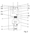
- FIG. 2 shows a second embodiment of a converter system according to the invention shown, which is characterized by the first and above described embodiment 1 differentiates in that the first voltage inverter 5 of the partial converter system 2 according to the invention via a resonance capacitance 10 with the second connection 22b of the primary winding 8 of the transformer 7 is connected.
- This resonant capacitance 10 advantageously serves to form a resonant circuit, with which a smooth switching of the power semiconductor switch switches of the first Voltage inverter 5, in particular at a zero voltage and or one Zero current, is possible.
- the partial converter system 2 of the converter system is the Output of the converter 6 according to the invention with a DC voltage filter circuit 11 connected to smooth the DC output voltage.
- the DC voltage filter circuit 11 preferably has a DC voltage inductance and a DC filter capacity.
- harmonic filter circuit 12 is provided, which has a series resonant circuit.
- the series resonant circuit is on a harmonic frequency, in particular to the second harmonic vibration related to the Basic oscillation of the AC voltage at the output of the first voltage inverter 5 and is used to filter this harmonic in the DC voltage at the output of the converter 6.
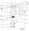
- FIG. 3a of the converter system according to the invention is the converter system by several Partial converter systems 2 formed, whereby advantageously even higher powers are transmitted can be.
- 3a are in the event that the converter system by several Partial converter systems 2 is formed, the partial converter systems 2 on the output side in series and connected in parallel on the input side.
- the series connection of the Partial converter systems 2 add up the individual partial DC voltages at the outputs of the partial converter systems 2 to a total DC voltage, which is then for transmission a desired high performance can be used.
- An adaptation to one required high performance is achieved by varying the number of partial converter systems 2 Power converter system very easily possible.
- a second voltage inverter 27 is provided which is connected on the input side the first and second input terminals 23a, 23b of the first voltage inverter 5 is connected.
- the second voltage inverter 27 is connected to the midpoint 4 connected on the input side.
- the second voltage inverter is on the output side 27 connected to the second connection 22b of the primary winding 8 of the transformer 7, so that a parallel connection of the second voltage inverter 27 to the first Voltage inverter 5 is formed.
- the second voltage inverter 27 is also, like the first voltage inverter 5, as a step circuit for generation three switching voltage levels and thus has the previously described Structure according to FIG. 4. It has also been used for the second voltage inverter 27 proven to be advantageous, the switching frequency of the active switching elements of the second voltage inverter 27 in the range between 300 Hz and 2000 Hz to choose from the switching operations of the active switching elements generated harmonics as possible to keep low.
- a fifth embodiment of the converter system according to the invention shown in FIG. 3c is the second voltage inverter 27 on the input side with the first and second input terminal 23a, 23b of the first voltage inverter 5 connected is.
- the second voltage inverter 27 with the midpoint connection 4 is on the input side connected.
- the second voltage inverter 27 is in place of the center connection 4 to the first connection 22a of the primary winding 8 of the Transformer 7 connected, so that a parallel connection of the second voltage inverter 27 to the first voltage inverter 5 is formed.
- the second voltage inverter 27, like the first voltage inverter 5, is also a step circuit trained to generate three switching voltage levels and thus has the 4 described above.
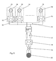
- the wind energy system 5 shows an embodiment of a wind energy system according to the invention, in particular shown with a DC voltage transmission system 17.
- the wind energy system 5 comprises at least one wind turbine 13, each one of one the clarity because of the rotor-driven generator, not shown in FIG. 5 14, which via a rectifier unit 15 to the DC voltage transmission system 17 is connected.
- 5 is the DC voltage transmission system 17 connected to a converter network coupling station 18, which is coupled via a Mains transformer 19 to a common electrical supply network 20 is used.
- the rectifier unit 15 via a converter system according to the invention to increase the DC voltage, in particular the DC transmission voltage of the DC voltage transmission system 17, with the DC voltage transmission system 17 connected.
- This increase in the DC transmission voltage has a particular effect advantageous for DC transmission systems with long transmission paths from how they often occur in off-shore applications of wind energy systems.
- losses, in particular heat losses if the DC transmission voltage is too low due to a large current due to the high power to be transmitted are caused to be minimized with an increased DC transmission voltage.
- line material which is too low DC transmission voltage and at the same time high power to be transmitted is required to be able to handle the correspondingly high current.
- the rectifier units 15 via a DC voltage busbar 16 are connected in parallel to advantageously provide a redundant supply of the rectifier units 15 to achieve
- the wind energy system according to the invention shown in FIG. 5 has also been found proven to be advantageous that the converter 6 of the converter system preferably Has active switching elements and / or passive switching elements, with active Switching elements, in particular by means of controllable semiconductor switches, the direct transmission voltage can advantageously be varied in height by a suitable control can.
- the converter 6 preferably has passive switching elements, especially diodes.
- passive switching elements especially diodes.
- control circuits for the Switching elements can be omitted, which in particular requires maintenance and a possible Failure rate, for example in off-shore applications of wind energy systems, which due to the weather conditions in the sea only during certain seasons serviced, significantly reduced.
- the increase in DC transmission voltage achieved very easily and with little circuitry, as a possible participation the rectifier unit 15 not at the increase in transmission voltage takes place and thus a considerable cost, insulation and circuitry effort by redesigning and replacement of power electronic switching elements of the rectifier unit 15 is not applicable.
Landscapes
- Engineering & Computer Science (AREA)
- Power Engineering (AREA)
- Inverter Devices (AREA)
- Dc-Dc Converters (AREA)
- Power Conversion In General (AREA)
- Supply And Distribution Of Alternating Current (AREA)
Abstract
Description
Leistung übertragen kann, da die doppelte Gleichspannung des Gleichspannungskreises bei Schaltelementen mit gleicher Spannungsfestigkeit angelegt und geschaltet werden kann. Zudem wird eine vorteilhafte Reduktion der Oberschwingungen erzielt, da drei Schaltspannungsniveaus geschaltet werden können und somit ein exakterer sinusförmiger Verlauf der zu erzeugenden Wechselspannung generiert werden kann.
- Fig. 1
- eine erste Ausführungsform eines erfindungsgemässen Stromrichtersystems,
- Fig. 2
- eine zweite Ausführungsform eines erfindungsgemässen Stromrichter-systems,
- Fig. 3a
- eine dritte Ausführungsform eines erfindungsgemässen Stromrichtersystems,
- Fig. 3b
- eine vierte Ausführungsform eines erfindungsgemässen Stromrichter-systems,
- Fig. 3c
- eine fünfte Ausführungsform eines erfindungsgemässen Stromrichter-systems,
- Fig. 4
- eine Ausführungsform einer erfindungsgemässen Stufenschaltung zur Erzeugung dreier Spannungsschaltstufen und
- Fig. 5
- eine Ausführungsform eines erfindungsgemässen Windenergiesystems.
- 2
- Teilstromrichtersystem
- 3
- Gleichspannungskreis
- 4
- Mittelpunktanschluss
- 5
- erster Spannungswechselrichter
- 6
- Umrichter
- 7
- Transformator
- 8
- Primärseite
- 9
- Sekundärseite
- 10
- Resonanzkapazität
- 11
- Gleichspannungsfilterschaltung
- 12
- Oberschwingungsfilterschaltung
- 13
- Windenergieanlage
- 14
- Generator
- 15
- Gleichrichtereinheit
- 16
- Gleichspannungsverschienung
- 17
- Gleichspannungsübertragungssystem
- 18
- Stromrichternetzkopplungsstation
- 19
- Netztransformator
- 20
- elektrisches Versorgungsnetz
- 21a, 21b
- Gleichspannungskapazität
- 22a
- erster Anschluss der Primärseite des Transformators
- 22b
- zweiter Anschluss der Primärseite des Transformators
- 23a,
- erster Eingangsanschluss des ersten Spannungswechselrichters
- 23b
- zweiter Eingangsanschluss des ersten Spannungswechselrichters
- 23c
- dritter Eingangsanschluss des ersten Spannungswechselrichters
- 24
- Mittelpunktspannungsstufe
- 25
- erste Schaltstufe
- 26
- zweite Schaltstufe
- 27
- zweiter Spannungswechselrichter
Claims (15)
- Stromrichtersystem zur Erhöhung einer Gleichspannung gebildet durch mindestens ein Teilstromrichtersystem (2) mit einem an einen ersten Spannungswechselrichter (5) angeschlossenen eingangsseitigen Gleichspannungskreis (3) und einen durch mindestens zwei in Reihe geschalteten Gleichspannungskapazitäten (21a, 21b) des Gleichspannungszwischenkreises (3) gebildeten Mittelpunktanschlusses (4), der an einen ersten Anschluss (22a) der Primärwicklung (8) eines Transformators (7) angeschlossen ist, dessen zweiter Anschluss (22b) der Primärwicklung (8) an den Ausgang des ersten Spannungswechselrichters (5) angeschlossen ist, wobei die Sekundärwicklung (9) des Transformators (7) mit dem Eingang eines ausgangsseitigen und zur Erzeugung einer ausgangsseitigen Gleichspannung vorgesehenen Umrichters (6) verbunden ist, dadurch gekennzeichnet, dass der erste Spannungswechselrichter (5) mit einem ersten und einem zweiten Eingangsanschluss (23a; 23b) mit dem Gleichspannungszwischenkreis (3) verbunden ist und dass der Mittelpunktanschluss (4) über einen dritten Eingangsanschluss (23c) des ersten Spannungswechselrichters (5) mit einer Mittelpunktspannungsstufe (24) des als Stufenschaltung zur Erzeugung dreier Schaltspannungsniveaus ausgebildeten ersten Spannungswechselrichters (5) verbunden ist.
- Stromrichtersystem nach Anspruch 1, dadurch gekennzeichnet, dass die Mittelpunktspannungsstufe (24) mit einer ersten zur Erzeugung eines positiven Schaltspannungsniveaus vorgesehenen Schaltstufe (25) der Stufenschaltung verbunden ist, und dass der Gleichspannungszwischenkreis (3) über den ersten Eingangsanschluss (23a) des ersten Spannungswechselrichters (5) mit der ersten Schaltstufe (25) verbunden ist.
- Stromrichtersystem nach Anspruch 1 oder 2, dadurch gekennzeichnet, dass die Mittelpunktspannungsstufe (24) mit einer zweiten zur Erzeugung eines negativen Schaltspannungsniveaus vorgesehenen Schaltstufe (26) der Stufenschaltung verbunden ist, und dass der Gleichspannungszwischenkreis (3) über den zweiten Eingangsanschluss (23b) des ersten Spannungswechselrichters (5) mit der zweiten Schaltstufe (26) verbunden ist.
- Stromrichtersystem nach Anspruch einem der Ansprüche 1 bis 3, dadurch gekennzeichnet, dass ein zweiter Spannungswechselrichter (27) vorgesehen ist, der eingangsseitig mit dem ersten und zweiten Eingangsanschluss (23a; 23b) des ersten Spannungswechselrichters (5) und mit dem Mittelpunktanschluss (4) eingangseitig verbunden ist und dass der zweite Spannungswechselrichter (27) ausgangsseitig an den zweiten Anschluss (22b) der Primärwicklung (8) angeschlossen ist.
- Stromrichtersystem nach Anspruch einem der Ansprüche 1 bis 3, dadurch gekennzeichnet, dass ein zweiter Spannungswechselrichter (27) vorgesehen ist, der eingangsseitig mit dem ersten und zweiten Eingangsanschluss (23a; 23b) des ersten Spannungswechselrichters (5) und mit dem Mittelpunktanschluss (4) eingangsseitig verbunden ist und dass anstelle des Mittelpunktanschlusses (4) der zweite Spannungswechselrichter (27) ausgangsseitig an den ersten Anschluss (22a) der Primärwicklung (8) angeschlossen ist.
- Stromrichtersystem nach einem der vorhergehenden Ansprüche, dadurch gekennzeichnet, dass die Schaltfrequenz der aktiven Schaltelemente des ersten Spannungswechselrichters (5) im Bereich zwischen 300 Hz und 3000 Hz gewählt ist.
- Stromrichtersystem nach Anspruch 4 oder 5, dadurch gekennzeichnet, dass die Schaltfrequenz der aktiven Schaltelemente des zweiten Spannungswechselrichters (27) im Bereich zwischen 300 Hz und 3000 Hz gewählt ist.
- Stromrichtersystem nach einem der vorhergehenden Ansprüche, dadurch gekennzeichnet, dass das Übersetzungsverhältnis zwischen der Primärseite (8) und der Sekundärseite (9) des Transformators (7) im Bereich zwischen 1:5 und 1: 50 gewählt ist.
- Stromrichtersystem nach einem der vorhergehenden Ansprüche, dadurch gekennzeichnet, dass der erste Spannungswechselrichter (5) über eine Resonanzkapazität (10) mit dem zweiten Anschluss (22b) der Primärwicklung des Transformators (7) verbunden ist.
- Stromrichtersystem nach einem der vorhergehenden Ansprüche, dadurch gekennzeichnet, dass der Ausgang des Umrichters (6) mit einer Gleichspannungsfilterschaltung (11) verbunden ist, die eine Gleichspannungsfilterinduktivität und eine Gleichspannungsfilterkapazität aufweist.
- Stromrichtersystem nach Anspruch 10, dadurch gekennzeichnet, dass eine parallel zur Gleichspannungsfilterschaltung (11) geschaltete Oberschwingungsfilterschaltung (12) vorgesehen ist, die einen auf eine Oberschwingungsfrequenz abgestimmten Serienschwingkreis aufweist.
- Stromrichtersystem nach einem der vorhergehenden Ansprüche, dadurch gekennzeichnet, dass die Teilstromrichtersysteme (2) ausgangsseitig in Reihe geschaltet sind, und dass die Teilstromrichtersysteme (2) eingangsseitig parallel geschaltet sind.
- Windenergiesystem mit mindestens einer Windenergieanlage (13), die je einen von einem Rotor angetriebenen Generator (14) aufweist, der über eine Gleichrichtereinheit (15) an ein Gleichspannungsübertragungssystem (17) angeschlossen ist, das mit einer Stromrichternetzkopplungsstation (18) verbunden ist, die über einen Netztransformator (19) an ein elektrisches Versorgungsnetz (20) angekoppelt ist, dadurch gekennzeichnet, dass die Gleichrichtereinheit (15) über ein zur Erhöhung einer Gleichspannung vorgesehenes Stromrichtersystem, insbesondere nach einem der Ansprüche 1 bis 11, mit dem Gleichspannungsübertragungssystem (17) verbunden ist.
- Windenergiesystem nach Anspruch 13, dadurch gekennzeichnet, dass die Gleichrichtereinheiten (15) mehrerer Windenergieanlagen (18) über eine Gleichspannungsverschienung parallel geschaltet sind.
- Windenergiesystem nach Anspruch 13 oder 14, dadurch gekennzeichnet, dass der Umrichter (6) des Stromrichtersystems passive Schaltelemente, insbesondere Dioden, und/oder aktive Schaltelemente, insbesondere ansteuerbare Halbleiterschalter, aufweist.
Priority Applications (2)
| Application Number | Priority Date | Filing Date | Title |
|---|---|---|---|
| EP01811201A EP1215809B1 (de) | 2000-12-18 | 2001-12-10 | Stromrichtersystem zur Erhöhung einer Gleichspannung |
| DK01811201T DK1215809T3 (da) | 2000-12-18 | 2001-12-10 | Omformersystem til forögelse af en jævnspænding |
Applications Claiming Priority (3)
| Application Number | Priority Date | Filing Date | Title |
|---|---|---|---|
| EP00811204 | 2000-12-18 | ||
| EP00811204 | 2000-12-18 | ||
| EP01811201A EP1215809B1 (de) | 2000-12-18 | 2001-12-10 | Stromrichtersystem zur Erhöhung einer Gleichspannung |
Publications (3)
| Publication Number | Publication Date |
|---|---|
| EP1215809A2 true EP1215809A2 (de) | 2002-06-19 |
| EP1215809A3 EP1215809A3 (de) | 2004-05-19 |
| EP1215809B1 EP1215809B1 (de) | 2005-03-23 |
Family
ID=8175085
Family Applications (1)
| Application Number | Title | Priority Date | Filing Date |
|---|---|---|---|
| EP01811201A Expired - Lifetime EP1215809B1 (de) | 2000-12-18 | 2001-12-10 | Stromrichtersystem zur Erhöhung einer Gleichspannung |
Country Status (6)
| Country | Link |
|---|---|
| US (1) | US6704213B2 (de) |
| EP (1) | EP1215809B1 (de) |
| AT (1) | ATE291789T1 (de) |
| CA (1) | CA2364416A1 (de) |
| DE (1) | DE50105680D1 (de) |
| DK (1) | DK1215809T3 (de) |
Families Citing this family (6)
| Publication number | Priority date | Publication date | Assignee | Title |
|---|---|---|---|---|
| US7366297B1 (en) * | 2003-05-21 | 2008-04-29 | Cisco Technology, Inc. | Method and system for converting alternating current to ethernet in-line power |
| CN101361254B (zh) * | 2005-11-24 | 2012-05-30 | 株式会社小松制作所 | Ac连接双方向dc—dc转换器、使用了该转换器的混合电源系统及混合动力车辆 |
| US8634216B2 (en) | 2010-07-08 | 2014-01-21 | Solarbridge Technologies, Inc. | Communication within a power inverter using transformer voltage frequency |
| KR101394870B1 (ko) | 2013-06-18 | 2014-05-13 | 현대자동차주식회사 | 연료전지의 출력 제어 방법 |
| US9571022B2 (en) * | 2013-08-30 | 2017-02-14 | Abb Schweiz Ag | Electrical generator with integrated hybrid rectification system comprising active and passive rectifiers connected in series |
| CN112994466B (zh) * | 2021-02-23 | 2022-06-28 | 浙江大学 | 一种宽调压范围的变换器 |
Family Cites Families (4)
| Publication number | Priority date | Publication date | Assignee | Title |
|---|---|---|---|---|
| US4462070A (en) | 1982-01-29 | 1984-07-24 | Toyo Denki Seizo Kabushiki Kaisha | DC-DC Converter provided with an AC link |
| DE4131763A1 (de) * | 1991-09-24 | 1993-03-25 | Siemens Ag | Verfahren zur reduzierung von spannungsschwingungen eines zwischenkreismittenanschlusses eines dreipunktumrichters |
| JPH077957A (ja) | 1993-06-14 | 1995-01-10 | Toshiba Corp | 電力変換装置 |
| DE19620906C2 (de) | 1996-05-24 | 2000-02-10 | Siemens Ag | Windenergiepark |
-
2001
- 2001-12-05 CA CA002364416A patent/CA2364416A1/en not_active Abandoned
- 2001-12-07 US US10/005,601 patent/US6704213B2/en not_active Expired - Fee Related
- 2001-12-10 EP EP01811201A patent/EP1215809B1/de not_active Expired - Lifetime
- 2001-12-10 AT AT01811201T patent/ATE291789T1/de not_active IP Right Cessation
- 2001-12-10 DE DE50105680T patent/DE50105680D1/de not_active Expired - Fee Related
- 2001-12-10 DK DK01811201T patent/DK1215809T3/da active
Also Published As
| Publication number | Publication date |
|---|---|
| CA2364416A1 (en) | 2002-06-18 |
| EP1215809A3 (de) | 2004-05-19 |
| DE50105680D1 (de) | 2005-04-28 |
| ATE291789T1 (de) | 2005-04-15 |
| US20020044460A1 (en) | 2002-04-18 |
| US6704213B2 (en) | 2004-03-09 |
| DK1215809T3 (da) | 2005-08-01 |
| EP1215809B1 (de) | 2005-03-23 |
Similar Documents
| Publication | Publication Date | Title |
|---|---|---|
| EP1184963B1 (de) | Hochspannungs-Gleichstromwandler | |
| EP3172823B1 (de) | Gleichspannungswandler mit transformator | |
| EP1118151B1 (de) | Elektrische energieübertragungsanlage | |
| EP1311058B1 (de) | Frequenzumrichter | |
| DE69005647T2 (de) | System zum ableiten elektrischer energie von einer hochspannungs-gleichstrom-übertragungsleitung. | |
| EP3109463B1 (de) | Windparkanbindung mit diodengleichrichter | |
| EP3270501A1 (de) | Vorrichtung für die elektroenergieübertragung mittels hgü | |
| EP2107672A1 (de) | Dreiphasiger Wechselrichter ohne Verbindung zwischen dem Neutralleiter des Netzes und dem Mittelpunkt des Zwischenkreises | |
| EP3622621B1 (de) | Multilevelstromrichter | |
| EP1215809B1 (de) | Stromrichtersystem zur Erhöhung einer Gleichspannung | |
| EP3220527A1 (de) | Modularer mehrstufenumrichter | |
| DE3404076A1 (de) | Gleichstrom-kurzkupplung | |
| EP3656032B1 (de) | Serienkompensationseinrichtung | |
| EP0570839A2 (de) | Schaltungsanordnung zur Kompensation von Spannungsabfällen an Versorgungsleitungen bzw. zur Minderung der Oberwellen des Stromes | |
| EP3513475B1 (de) | Anlage zum übertragen elektrischer leistung mit filtereinheit | |
| WO2021013341A1 (de) | Vorrichtung zum verbinden zweier wechselspannungsnetze und verfahren zum betreiben der vorrichtung | |
| EP3363091B1 (de) | Vorrichtung und verfahren zum steuern eines lastflusses in einem wechselspannungsnetz | |
| DE102013109714A1 (de) | Verfahren zum Betreiben einer elektrischen Schaltung sowie elektrische Schaltung | |
| DE69400477T2 (de) | Verfahren und vorrichtung zum verbinden zweier synchroner mehrphasiger wechselstromnetze | |
| EP3656031B1 (de) | Anordnung zur frequenzstabilisierung | |
| WO2021228769A1 (de) | 3-phasen pv wechselrichter mit 2-phasigem inselbetrieb bei netzstörung | |
| EP1298781B1 (de) | Stromrichterschaltungsanordnung sowie Verfahren zur Anpassung einer variablen Gleichspannung | |
| EP2958225A2 (de) | Verfahren zum betreiben eines einen spannungszwischenkreis aufweisenden modularen mehrstufenstromrichters | |
| EP2262087A1 (de) | Wandlerschaltung mit einem Umrichter | |
| EP3331118A1 (de) | Anlage zum übertragen elektrischer leistung |
Legal Events
| Date | Code | Title | Description |
|---|---|---|---|
| PUAI | Public reference made under article 153(3) epc to a published international application that has entered the european phase |
Free format text: ORIGINAL CODE: 0009012 |
|
| AK | Designated contracting states |
Kind code of ref document: A2 Designated state(s): AT BE CH CY DE DK ES FI FR GB GR IE IT LI LU MC NL PT SE TR |
|
| AX | Request for extension of the european patent |
Free format text: AL;LT;LV;MK;RO;SI |
|
| PUAL | Search report despatched |
Free format text: ORIGINAL CODE: 0009013 |
|
| AK | Designated contracting states |
Kind code of ref document: A3 Designated state(s): AT BE CH CY DE DK ES FI FR GB GR IE IT LI LU MC NL PT SE TR |
|
| AX | Request for extension of the european patent |
Extension state: AL LT LV MK RO SI |
|
| GRAP | Despatch of communication of intention to grant a patent |
Free format text: ORIGINAL CODE: EPIDOSNIGR1 |
|
| 17P | Request for examination filed |
Effective date: 20040624 |
|
| GRAS | Grant fee paid |
Free format text: ORIGINAL CODE: EPIDOSNIGR3 |
|
| GRAA | (expected) grant |
Free format text: ORIGINAL CODE: 0009210 |
|
| AKX | Designation fees paid |
Designated state(s): AT BE CH CY DE DK ES FI FR GB GR IE IT LI LU MC NL PT SE TR |
|
| AK | Designated contracting states |
Kind code of ref document: B1 Designated state(s): AT BE CH CY DE DK ES FI FR GB GR IE IT LI LU MC NL PT SE TR |
|
| PG25 | Lapsed in a contracting state [announced via postgrant information from national office to epo] |
Ref country code: TR Free format text: LAPSE BECAUSE OF FAILURE TO SUBMIT A TRANSLATION OF THE DESCRIPTION OR TO PAY THE FEE WITHIN THE PRESCRIBED TIME-LIMIT Effective date: 20050323 Ref country code: IT Free format text: LAPSE BECAUSE OF FAILURE TO SUBMIT A TRANSLATION OF THE DESCRIPTION OR TO PAY THE FEE WITHIN THE PRESCRIBED TIME-LIMIT;WARNING: LAPSES OF ITALIAN PATENTS WITH EFFECTIVE DATE BEFORE 2007 MAY HAVE OCCURRED AT ANY TIME BEFORE 2007. THE CORRECT EFFECTIVE DATE MAY BE DIFFERENT FROM THE ONE RECORDED. Effective date: 20050323 Ref country code: IE Free format text: LAPSE BECAUSE OF FAILURE TO SUBMIT A TRANSLATION OF THE DESCRIPTION OR TO PAY THE FEE WITHIN THE PRESCRIBED TIME-LIMIT Effective date: 20050323 Ref country code: FI Free format text: LAPSE BECAUSE OF FAILURE TO SUBMIT A TRANSLATION OF THE DESCRIPTION OR TO PAY THE FEE WITHIN THE PRESCRIBED TIME-LIMIT Effective date: 20050323 |
|
| REG | Reference to a national code |
Ref country code: GB Ref legal event code: FG4D Free format text: NOT ENGLISH |
|
| REG | Reference to a national code |
Ref country code: CH Ref legal event code: EP |
|
| REG | Reference to a national code |
Ref country code: IE Ref legal event code: FG4D Free format text: GERMAN |
|
| REF | Corresponds to: |
Ref document number: 50105680 Country of ref document: DE Date of ref document: 20050428 Kind code of ref document: P |
|
| PG25 | Lapsed in a contracting state [announced via postgrant information from national office to epo] |
Ref country code: GR Free format text: LAPSE BECAUSE OF FAILURE TO SUBMIT A TRANSLATION OF THE DESCRIPTION OR TO PAY THE FEE WITHIN THE PRESCRIBED TIME-LIMIT Effective date: 20050623 |
|
| REG | Reference to a national code |
Ref country code: DK Ref legal event code: T3 |
|
| GBT | Gb: translation of ep patent filed (gb section 77(6)(a)/1977) |
Effective date: 20050711 |
|
| PG25 | Lapsed in a contracting state [announced via postgrant information from national office to epo] |
Ref country code: PT Free format text: LAPSE BECAUSE OF FAILURE TO SUBMIT A TRANSLATION OF THE DESCRIPTION OR TO PAY THE FEE WITHIN THE PRESCRIBED TIME-LIMIT Effective date: 20050907 |
|
| REG | Reference to a national code |
Ref country code: IE Ref legal event code: FD4D |
|
| PG25 | Lapsed in a contracting state [announced via postgrant information from national office to epo] |
Ref country code: GB Free format text: LAPSE BECAUSE OF NON-PAYMENT OF DUE FEES Effective date: 20051210 Ref country code: CY Free format text: LAPSE BECAUSE OF FAILURE TO SUBMIT A TRANSLATION OF THE DESCRIPTION OR TO PAY THE FEE WITHIN THE PRESCRIBED TIME-LIMIT Effective date: 20051210 Ref country code: AT Free format text: LAPSE BECAUSE OF NON-PAYMENT OF DUE FEES Effective date: 20051210 |
|
| PG25 | Lapsed in a contracting state [announced via postgrant information from national office to epo] |
Ref country code: ES Free format text: LAPSE BECAUSE OF NON-PAYMENT OF DUE FEES Effective date: 20051212 |
|
| PG25 | Lapsed in a contracting state [announced via postgrant information from national office to epo] |
Ref country code: MC Free format text: LAPSE BECAUSE OF NON-PAYMENT OF DUE FEES Effective date: 20051231 Ref country code: LU Free format text: LAPSE BECAUSE OF NON-PAYMENT OF DUE FEES Effective date: 20051231 Ref country code: LI Free format text: LAPSE BECAUSE OF NON-PAYMENT OF DUE FEES Effective date: 20051231 Ref country code: CH Free format text: LAPSE BECAUSE OF NON-PAYMENT OF DUE FEES Effective date: 20051231 Ref country code: BE Free format text: LAPSE BECAUSE OF NON-PAYMENT OF DUE FEES Effective date: 20051231 |
|
| PG25 | Lapsed in a contracting state [announced via postgrant information from national office to epo] |
Ref country code: DK Free format text: LAPSE BECAUSE OF NON-PAYMENT OF DUE FEES Effective date: 20060102 |
|
| PLBE | No opposition filed within time limit |
Free format text: ORIGINAL CODE: 0009261 |
|
| STAA | Information on the status of an ep patent application or granted ep patent |
Free format text: STATUS: NO OPPOSITION FILED WITHIN TIME LIMIT |
|
| ET | Fr: translation filed | ||
| 26N | No opposition filed |
Effective date: 20051227 |
|
| PG25 | Lapsed in a contracting state [announced via postgrant information from national office to epo] |
Ref country code: NL Free format text: LAPSE BECAUSE OF NON-PAYMENT OF DUE FEES Effective date: 20060701 Ref country code: DE Free format text: LAPSE BECAUSE OF NON-PAYMENT OF DUE FEES Effective date: 20060701 |
|
| REG | Reference to a national code |
Ref country code: DK Ref legal event code: EBP |
|
| REG | Reference to a national code |
Ref country code: CH Ref legal event code: PL |
|
| GBPC | Gb: european patent ceased through non-payment of renewal fee |
Effective date: 20051210 |
|
| NLV4 | Nl: lapsed or anulled due to non-payment of the annual fee |
Effective date: 20060701 |
|
| REG | Reference to a national code |
Ref country code: ES Ref legal event code: FD2A Effective date: 20051212 |
|
| BERE | Be: lapsed |
Owner name: ABB SCHWEIZ A.G. Effective date: 20051231 |
|
| PG25 | Lapsed in a contracting state [announced via postgrant information from national office to epo] |
Ref country code: SE Free format text: LAPSE BECAUSE OF FAILURE TO SUBMIT A TRANSLATION OF THE DESCRIPTION OR TO PAY THE FEE WITHIN THE PRESCRIBED TIME-LIMIT Effective date: 20050623 |
|
| PG25 | Lapsed in a contracting state [announced via postgrant information from national office to epo] |
Ref country code: FR Free format text: LAPSE BECAUSE OF NON-PAYMENT OF DUE FEES Effective date: 20051231 |
|
| REG | Reference to a national code |
Ref country code: FR Ref legal event code: ST Effective date: 20111125 |