EP1216794A1 - Système et methode pour la finission des surfaces concaves à l'aide des particules abrasives, accelerées par electromagnetisme - Google Patents
Système et methode pour la finission des surfaces concaves à l'aide des particules abrasives, accelerées par electromagnetisme Download PDFInfo
- Publication number
- EP1216794A1 EP1216794A1 EP01127843A EP01127843A EP1216794A1 EP 1216794 A1 EP1216794 A1 EP 1216794A1 EP 01127843 A EP01127843 A EP 01127843A EP 01127843 A EP01127843 A EP 01127843A EP 1216794 A1 EP1216794 A1 EP 1216794A1
- Authority
- EP
- European Patent Office
- Prior art keywords
- nozzle
- solenoid
- fluid
- jet
- tip
- Prior art date
- Legal status (The legal status is an assumption and is not a legal conclusion. Google has not performed a legal analysis and makes no representation as to the accuracy of the status listed.)
- Withdrawn
Links
- 239000012530 fluid Substances 0.000 title claims abstract description 87
- 238000000034 method Methods 0.000 title claims abstract description 10
- 230000005291 magnetic effect Effects 0.000 claims abstract description 44
- 230000005294 ferromagnetic effect Effects 0.000 claims abstract description 16
- 238000007493 shaping process Methods 0.000 claims description 22
- 238000004804 winding Methods 0.000 claims description 22
- 239000003302 ferromagnetic material Substances 0.000 claims description 8
- 230000001427 coherent effect Effects 0.000 claims description 7
- 238000007599 discharging Methods 0.000 claims description 4
- 238000004519 manufacturing process Methods 0.000 claims description 4
- 230000006872 improvement Effects 0.000 claims description 3
- 230000009467 reduction Effects 0.000 abstract description 2
- 230000002093 peripheral effect Effects 0.000 abstract 1
- 239000002245 particle Substances 0.000 description 5
- 238000005498 polishing Methods 0.000 description 5
- 239000000758 substrate Substances 0.000 description 5
- 239000012141 concentrate Substances 0.000 description 4
- 230000004323 axial length Effects 0.000 description 3
- 239000000463 material Substances 0.000 description 3
- XEEYBQQBJWHFJM-UHFFFAOYSA-N Iron Chemical compound [Fe] XEEYBQQBJWHFJM-UHFFFAOYSA-N 0.000 description 2
- UQSXHKLRYXJYBZ-UHFFFAOYSA-N Iron oxide Chemical compound [Fe]=O UQSXHKLRYXJYBZ-UHFFFAOYSA-N 0.000 description 2
- 239000003082 abrasive agent Substances 0.000 description 2
- 206010061592 cardiac fibrillation Diseases 0.000 description 2
- 239000000919 ceramic Substances 0.000 description 2
- 229910000420 cerium oxide Inorganic materials 0.000 description 2
- 229910003460 diamond Inorganic materials 0.000 description 2
- 239000010432 diamond Substances 0.000 description 2
- 239000000428 dust Substances 0.000 description 2
- 238000005516 engineering process Methods 0.000 description 2
- 230000002600 fibrillogenic effect Effects 0.000 description 2
- -1 for example Substances 0.000 description 2
- 239000011521 glass Substances 0.000 description 2
- 238000003754 machining Methods 0.000 description 2
- 239000006249 magnetic particle Substances 0.000 description 2
- 239000002184 metal Substances 0.000 description 2
- 229910052751 metal Inorganic materials 0.000 description 2
- BMMGVYCKOGBVEV-UHFFFAOYSA-N oxo(oxoceriooxy)cerium Chemical compound [Ce]=O.O=[Ce]=O BMMGVYCKOGBVEV-UHFFFAOYSA-N 0.000 description 2
- 239000004033 plastic Substances 0.000 description 2
- 229920003023 plastic Polymers 0.000 description 2
- 239000007787 solid Substances 0.000 description 2
- 230000003319 supportive effect Effects 0.000 description 2
- 229910000975 Carbon steel Inorganic materials 0.000 description 1
- RYGMFSIKBFXOCR-UHFFFAOYSA-N Copper Chemical compound [Cu] RYGMFSIKBFXOCR-UHFFFAOYSA-N 0.000 description 1
- 229910000831 Steel Inorganic materials 0.000 description 1
- PNEYBMLMFCGWSK-UHFFFAOYSA-N aluminium oxide Inorganic materials [O-2].[O-2].[O-2].[Al+3].[Al+3] PNEYBMLMFCGWSK-UHFFFAOYSA-N 0.000 description 1
- 230000015572 biosynthetic process Effects 0.000 description 1
- 239000010962 carbon steel Substances 0.000 description 1
- 230000015556 catabolic process Effects 0.000 description 1
- 239000004927 clay Substances 0.000 description 1
- 239000010960 cold rolled steel Substances 0.000 description 1
- 238000010276 construction Methods 0.000 description 1
- 238000001816 cooling Methods 0.000 description 1
- 229910052802 copper Inorganic materials 0.000 description 1
- 239000010949 copper Substances 0.000 description 1
- 238000005520 cutting process Methods 0.000 description 1
- 238000006731 degradation reaction Methods 0.000 description 1
- 230000000694 effects Effects 0.000 description 1
- 230000005611 electricity Effects 0.000 description 1
- 230000005484 gravity Effects 0.000 description 1
- 230000001939 inductive effect Effects 0.000 description 1
- 229910052742 iron Inorganic materials 0.000 description 1
- 150000002739 metals Chemical class 0.000 description 1
- 230000004048 modification Effects 0.000 description 1
- 238000012986 modification Methods 0.000 description 1
- 230000003287 optical effect Effects 0.000 description 1
- 238000011176 pooling Methods 0.000 description 1
- 238000005086 pumping Methods 0.000 description 1
- 238000003892 spreading Methods 0.000 description 1
- 230000007480 spreading Effects 0.000 description 1
- 230000006641 stabilisation Effects 0.000 description 1
- 238000011105 stabilization Methods 0.000 description 1
- 239000010935 stainless steel Substances 0.000 description 1
- 229910001220 stainless steel Inorganic materials 0.000 description 1
- 239000010959 steel Substances 0.000 description 1
- 239000000725 suspension Substances 0.000 description 1
- 239000012780 transparent material Substances 0.000 description 1
- 238000007514 turning Methods 0.000 description 1
Images


Classifications
-
- B—PERFORMING OPERATIONS; TRANSPORTING
- B24—GRINDING; POLISHING
- B24C—ABRASIVE OR RELATED BLASTING WITH PARTICULATE MATERIAL
- B24C11/00—Selection of abrasive materials or additives for abrasive blasts
-
- B—PERFORMING OPERATIONS; TRANSPORTING
- B24—GRINDING; POLISHING
- B24C—ABRASIVE OR RELATED BLASTING WITH PARTICULATE MATERIAL
- B24C5/00—Devices or accessories for generating abrasive blasts
-
- B—PERFORMING OPERATIONS; TRANSPORTING
- B24—GRINDING; POLISHING
- B24C—ABRASIVE OR RELATED BLASTING WITH PARTICULATE MATERIAL
- B24C5/00—Devices or accessories for generating abrasive blasts
- B24C5/08—Devices for generating abrasive blasts non-mechanically, e.g. of metallic abrasives by means of a magnetic field or by detonating cords
Definitions
- the present invention relates to methods and apparatus for shaping and polishing (finishing) a surface; more particularly to methods and apparatus for shaping and polishing a surface by the impingement of a magnetically-modifiable and magnetically-directable jet; and most particularly to a magnetically-efficient nozzle for extruding a jet of magnetically-solidified magnetorheological fluid in an upwards direction.
- Fluid jets containing abrasive particles are known to be used for cutting or shaping materials such as glass, ceramics, plastics and metals.
- This technology is known generally as abrasive stream finishing, or abrasive suspension jet machining, or abrasive flow machining.
- abrasive stream finishing or abrasive suspension jet machining, or abrasive flow machining.
- Such jets are impinged upon the substrate to be cut at a relatively high velocity, which may exceed 10 meters per second.
- the rate of material removal is a function of the kinetic energy of the jet, the sharpness, size, and hardness of the abrasive particles, the material of the substrate, the distance from the jet nozzle to the workpiece, and the angle of incidence of the jet.
- a technology is disclosed by which a magnetorheological (MR) fluid may be formed into a substantially coherent abrasive jet.
- a continuous stream of an MR fluid is directed through a non-ferromagnetic tube disposed axially of the helical windings of an electric solenoid.
- the tube defines a nozzle.
- the MR fluid is combined with a finely-divided abrasive material, for example, cerium oxide, diamond dust, or iron oxide, such that the abrasive is at least temporarily suspended therein.
- Flow of electricity through the solenoid creates an axial magnetic field within the windings which forms in the fluid a field-oriented structure of fibrils from the magnetic particles and thereby reversibly stiffens the flowing MR fluid into a virtually solid rod.
- the rod manifests a very high yield stress when sheared perpendicularly to the direction of flow and a relatively low shear stress when sheared in the direction of flow, as along the wall of the tube.
- anisotropic fibrillation allows the stiffened fluid to flow through the tube in the magnetic field.
- the MR rod ejected from the nozzle defines a highly-collimated, substantially solid jet of MR fluid.
- the MR fluid jet Upon leaving the nozzle, the exit of which is flush with the end of the windings, the MR fluid jet passes beyond the solenoid's magnetic field, and the anisotropic fibrillation within the jet begins to decay.
- remanent high viscosity, and thus consequent stabilization of the MR jet can persist for a sufficient time that the jet may travel up to several feet without significant spreading and loss of structure. This permits use of the abrasive jet to shape and/or polish the surface of a workpiece in a work zone at some distance from the nozzle.
- the prior art apparatus is not suited to finishing deeply concave surfaces. Because of splashing, pooling, and gravitational effects, we have found that the optimal finishing attitude for the abrasive jet is directly upwards. However, some of the spent MR fluid rebounding from the surface of the workpiece falls back onto the solenoid and nozzle, clogging the exit and subsequently deforming the jet.
- the nozzle is a non-ferromagnetic axial tube in which the magnetorheological fluid is stiffened progressively as it flows through the nozzle, creating a progressively increasing viscous drag in the nozzle which must be overcome by the system's pump.
- the pump and energy requirements for the prior art apparatus can become substantial.
- the solenoid lacks a ferro-magnetic core, the axial magnetic field is relatively weak, requiring an undesirably large and expensive solenoid.
- a magnetorheological finishing apparatus which can direct a stiffened jet in any direction, and especially in an upwards direction, continuously without becoming fouled by reflected fluid; which has a small pump by virtue of developing minimal viscous drag in delivery of the stiffened jet; and which has a small, magnetically-efficient solenoid by virtue of having a ferromagnetic solenoid core.
- the non-ferromagnetic nozzle (shown as item 30 therein) within the solenoid is replaced by a nozzle formed of ferromagnetic material such that the fluid is magnetically shielded within the nozzle.
- the improved nozzle serves as a ferromagnetic core for the solenoid, thereby increasing the strength of the axial magnetic field approximately 100-fold and permitting a significant reduction in the required size of the solenoid.
- the exit orifice of the nozzle is recessed within the solenoid turnings, rather than being flush with the end of the solenoid as in the prior art apparatus, thus creating a free space within the solenoid having an intense axial magnetic field near the exit orifice of the nozzle. Stiffening of the magnetorheological fluid is prevented substantially throughout the length of the nozzle until the fluid begins to enter the magnetic field as it leaves the nozzle; thus, there is no buildup of viscous drag through the nozzle. Formation of fibrils and consequent stiffening of the jet occurs principally in free space within the windings of the solenoid.
- the exit end of the nozzle is configured so that the magnetic field at the end of the nozzle and in the free space immediately downstream of the exit is intensified and collimated.
- the nozzle is provided with a radial array of longitudinal channels along its outer surface through which compressed air is injected to form a cylindrical air curtain which surrounds the jet as it emerges from the nozzle and solenoid. Returning MR fluid splashed from the workpiece is diverted by the air curtain and prevented from entering and fouling the solenoid exit and nozzle.
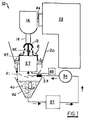
- an embodiment 10 of a polishing apparatus in accordance with the invention for finishing a substrate by vertically upwards abrasive jet comprises many of the elements disclosed in US Patent No. 5,971,835 except as modified below.
- a workpiece 12 to be finished for example, a molded blank for a glass or plastic lens or other optical element, or a similar metal or ceramic element requiring a very high level of accuracy in its final shape and the smoothness of its surface, and especially a deeply concave surface, is mounted in a supportive chuck 14, which in turn is supported for rotation in a machine spindle 16.
- the workpiece and chuck are surrounded by a shroud 20 which serves as a supportive housing and shield for the finishing operations. Outside the shroud is a multi-axis positioner 22, for example, a 5-axis CNC machine available from Boston Digital Corp., Milford, Massachusetts USA, the output shaft 24 of which is connected to machine spindle 16.
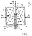
- a magnetic field-shaping subsystem 27 for forming a stiffened jet of magnetorheological fluid, as shown in detail in FIG. 2.
- An electric solenoid 28 capable of generating an axial magnetic field of, for example, about 1000 gauss is mounted such that an extension of the solenoid's axis in space intersects a portion of the surface to be finished on workpiece 12.
- the electric current provided to solenoid 28 may be varied to vary the strength of the magnetic field as desired.
- Solenoid 28 is wound conventionally with electrically conductive windings 29 preferably contained within a magnetically opaque shell 31 formed of, for example, steel.
- Solenoid 28 is provided along a portion of its axial length with an improved shaping nozzle 30, as described in detail below, which comprises the novel improvement of the present invention and which extends partially into the axial space in the solenoid.
- a pump 34 is connected for fluid flow between a fluid reservoir 36 and nozzle 30 to eject a collimated jet 35 of fluid from the nozzle.
- a pulse dampener 33 may be optionally included for suppressing pulses from pump 34.
- a controllable cooling means 37 which may be disposed within reservoir 36, is provided to temper the working fluid.
- Reservoir 36 contains an amount of a magnetorheological fluid 40 which preferably includes a finely-divided abrasive material such as, for example, cerium oxide, diamond dust, alumina, or combinations thereof.
- Spent MR fluid 37 flowing off of workpiece 12 collects in the bottom of shroud 20 and flows by gravity through an outlet tube 21 back into reservoir 36 for re-use, as shown in FIG. 1.
- Such stiffening in free space permits the use of a ferromagnetic material in construction of the nozzle, thereby providing a ferromagnetic core to solenoid 28, and eliminates the viscous drag experienced in the prior art apparatus caused by stiffening of fluid within the nozzle.
- the tip is recessed into the solenoid windings by a distance equal to at least the diameter of the nozzle, and preferably between one and four times such diameter.
- Shaping nozzle 30 is a tubular, generally cylindrical member having an axial bore 33 and an outer diameter substantially the same as the inner diameter of an optional tubular solenoid liner 42 which supports the windings 29 of solenoid 28 and in which nozzle 30 is disposed.
- the nozzle is formed of a ferromagnetic material such as, for example, carbon steel, such that MR fluid flowing through the tube is shielded from the solenoid's magnetic field.
- Liner 42 is formed of a ferromagnetically transparent material, for example, copper or stainless steel.
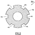
- Nozzle 30 preferably is provided with a plurality of longitudinal passageways 44 formed in the outer surface 46 of nozzle 30, which passageways terminate at a first end in a plenum 48 which is operationally attached to a conventional high-pressure air supply 50 for supplying air through the passageways during operation of apparatus 10.
- the passageways terminate at a second end around the periphery of the outer end 52 of shaping nozzle 30 such that a substantially cylindrical curtain of air 54 is formed and caused to flow axially from end 52 along the inner wall of sleeve 42 toward the open end 56 of liner 42.
- Air curtain 54 fills the space between jet 35 and liner 42 and continually flows out of the solenoid without disturbing jet 35. Spent MR fluid splashing or dripping from workpiece is deflected by the air curtain from entering the solenoid and fouling the continued delivery of jet 35, permitting continuous operation of apparatus 12.
- MR fluid 40 which has a low inherent viscosity, is drawn from reservoir 36 by pump 34 and pumped through nozzle 30.
- the magnetic moments of the magnetic particles become aligned to form fibrils, inducing a rod-like structure in the fluid.
- the fluid becomes highly stiffened to a physical texture like wet clay, and the apparent viscosity across the direction of flow becomes very high.
- the fluid is ejected from the nozzle in the direction of the workpiece as highly collimated jet 35. Because the end 52 of nozzle 30 is recessed within the solenoid, as shown in FIGS. 1 and 2, the jet continues to be stiffened during passage through the axial magnetic field after leaving nozzle. Because the cylindrical air curtain 54 surrounding the jet is travelling at a velocity comparable to that of the jet, the outer surface of the jet undergoes little or no degradation from aerodynamic turbulence.
- protuberant end 52 of nozzle 30 is an important feature of the present invention.
- protuberant end 52 is tapered from outer surface 46 toward bore 33, which taper acts to concentrate, collimate, and shape the magnetic field in the vicinity of tip 58 of end 52.
- a nozzle which is otherwise identical but which has a non-protuberant flush end provides a comparatively weak and gradually divergent magnetic field inferior to that achievable with a protuberant nozzle tip.
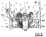
- protuberant 30 is further demonstrated by comparison of isoflux representations of protuberant 30 and non-protuberant 30' nozzle tips. While all protuberant longitudinal cross-sectional shapes, including, but not limited to, spherical, elliptical, and conical, are within the scope of the invention, the currently-preferred shape is frusto-conically tapered. A flush end to the nozzle (0° angle of taper, or 90° included angle 60), as shown in FIG. 7, cannot concentrate and shape the magnetic field around and beyond the tip of the nozzle, as shown for a tapered end 52 in FIG. 6.
- the angle of taper 60 may be varied to suit individual applications; an included angle of about 150°, as shown in FIG. 6, has been found to provided substantial shaping and narrowing of the jet.
- the nozzle may be provided as frusto-conical with a small flat end 58 to the cone.
- nozzle 30 is formed of a ferromagnetic material such as iron or cold-rolled steel tubing, thereby providing a ferromagnetic core over much of the axial length of the solenoid.
- the axial magnetic field is strengthened thereby by as much as several orders of magnitude, permitting use of a very much smaller and less expensive solenoid than that disclosed in the incorporated reference.
- the core does not extend the full axial length of solenoid 28, and consequently the axial magnetic field in the non-core portion is relatively weak, the protuberant tip on nozzle 30 concentrates and shapes the field extending axially from the tip, permitting the desired stiffening to occur in free space within the solenoid.
- Apparatus in accordance with the invention is especially useful in abrasive jet finishing of deeply concave surfaces when operated in a vertical mode as shown in FIG. 1.
- the present invention is still superior to that disclosed in the incorporated reference because of the smaller, less-expensive solenoid it allows.
- the air curtain feature of the invention may be omitted for economy if so desired.
- the invention relates to a method of making a coherent, substantially rigid fluid jet comprising the steps of: a) providing an electric solenoid; b) disposing within said solenoid at least a portion of a nozzle; c) providing a magnetorheological fluid; d) energizing said solenoid to provide a magnetic field within said solenoid; d1) forcing said magnetorheological fluid through said ferromagnetic nozzle; and e) ejecting said fluid from said nozzle to form a jet of said fluid in said free space.
Landscapes
- Engineering & Computer Science (AREA)
- Mechanical Engineering (AREA)
- Finish Polishing, Edge Sharpening, And Grinding By Specific Grinding Devices (AREA)
- Perforating, Stamping-Out Or Severing By Means Other Than Cutting (AREA)
Applications Claiming Priority (2)
| Application Number | Priority Date | Filing Date | Title |
|---|---|---|---|
| US09/718,658 US6561874B1 (en) | 2000-11-22 | 2000-11-22 | Apparatus and method for abrasive jet finishing of deeply concave surfaces using magnetorheological fluid |
| US718658 | 2000-11-22 |
Publications (1)
| Publication Number | Publication Date |
|---|---|
| EP1216794A1 true EP1216794A1 (fr) | 2002-06-26 |
Family
ID=24886960
Family Applications (1)
| Application Number | Title | Priority Date | Filing Date |
|---|---|---|---|
| EP01127843A Withdrawn EP1216794A1 (fr) | 2000-11-22 | 2001-11-22 | Système et methode pour la finission des surfaces concaves à l'aide des particules abrasives, accelerées par electromagnetisme |
Country Status (3)
| Country | Link |
|---|---|
| US (1) | US6561874B1 (fr) |
| EP (1) | EP1216794A1 (fr) |
| JP (1) | JP4070980B2 (fr) |
Cited By (4)
| Publication number | Priority date | Publication date | Assignee | Title |
|---|---|---|---|---|
| CN102172852A (zh) * | 2011-03-08 | 2011-09-07 | 湖南大学 | 复合振动磁流变超精密抛光方法 |
| CN103009263A (zh) * | 2011-09-23 | 2013-04-03 | 上海狮迈科技有限公司 | 一种环形磨料储存装置 |
| CN103612167A (zh) * | 2013-12-06 | 2014-03-05 | 李安林 | 吸附流研磨抛光法 |
| CN108381403A (zh) * | 2018-02-09 | 2018-08-10 | 东北石油大学 | 围压条件下磨料射流割缝试验台 |
Families Citing this family (26)
| Publication number | Priority date | Publication date | Assignee | Title |
|---|---|---|---|---|
| JP4331985B2 (ja) * | 2003-06-30 | 2009-09-16 | 株式会社不二製作所 | 被加工物の研磨方法及び前記方法に使用する噴流誘導手段並びに噴流規制手段 |
| US20050274454A1 (en) * | 2004-06-09 | 2005-12-15 | Extrand Charles W | Magneto-active adhesive systems |
| CN1328007C (zh) * | 2004-11-23 | 2007-07-25 | 哈尔滨工业大学 | 超声波磁流变复合抛光方法及装置 |
| US7959490B2 (en) | 2005-10-31 | 2011-06-14 | Depuy Products, Inc. | Orthopaedic component manufacturing method and equipment |
| US7521980B2 (en) * | 2006-08-25 | 2009-04-21 | Texas Instruments Incorporated | Process and temperature-independent voltage controlled attenuator and method |
| US7455573B2 (en) * | 2006-09-06 | 2008-11-25 | Lightmachinery Inc. | Fluid jet polishing with constant pressure pump |
| US7892071B2 (en) * | 2006-09-29 | 2011-02-22 | Depuy Products, Inc. | Orthopaedic component manufacturing method and equipment |
| JP5623437B2 (ja) * | 2009-03-06 | 2014-11-12 | キューイーディー・テクノロジーズ・インターナショナル・インコーポレーテッド | 磁気流体による基板研磨仕上げシステム |
| US8613640B2 (en) * | 2010-12-23 | 2013-12-24 | Qed Technologies International, Inc. | System for magnetorheological finishing of substrates |
| RU2461087C1 (ru) * | 2011-05-06 | 2012-09-10 | Государственное Научное Учреждение "Институт Тепло- И Массообмена Имени А.В. Лыкова Национальной Академии Наук Беларуси" | Текучая композиция с магнитореологическими свойствами |
| CN102873591B (zh) * | 2012-09-11 | 2016-06-01 | 上海交通大学 | 基于换能装置的型腔表面处理加工装置 |
| CN102873592B (zh) * | 2012-09-11 | 2015-09-16 | 青岛佳普智能材料应用有限公司 | 基于换能装置的表面光整加工装置 |
| CN102962732B (zh) * | 2012-12-05 | 2015-11-18 | 清华大学 | 一种电火花线切割贯通形型腔模具的磁流变抛光方法 |
| WO2015019888A1 (fr) * | 2013-08-07 | 2015-02-12 | コニカミノルタ株式会社 | Particules pour produit de polissage, procédé pour la production de produit de polissage et procédé de traitement par polissage |
| CN103465171A (zh) * | 2013-09-18 | 2013-12-25 | 中国科学院上海光学精密机械研究所 | 磁流变液回收管 |
| CN110052970B (zh) * | 2014-06-18 | 2021-05-04 | 新东工业株式会社 | 分级机构 |
| CN104128891B (zh) * | 2014-08-04 | 2016-10-05 | 安徽理工大学 | 悬浮磨料磁流体射流发生装置 |
| CN105983908A (zh) * | 2015-02-05 | 2016-10-05 | 福建省泉州海丝船舶评估咨询有限公司 | 一种船用超导电磁切割器 |
| CN107009274B (zh) * | 2017-05-12 | 2023-07-07 | 中国工程物理研究院机械制造工艺研究所 | 一种重力驱动传送磁流变抛光液的循环装置 |
| CN107234494B (zh) * | 2017-06-30 | 2024-01-16 | 浙江师范大学 | 一种磁流变浮动抛光装置与方法 |
| CN107263223B (zh) * | 2017-08-17 | 2023-09-05 | 安徽理工大学 | 基于永磁体的交流式磨料磁流体射流发生装置 |
| CN108515465A (zh) * | 2018-04-04 | 2018-09-11 | 中国科学院长春光学精密机械与物理研究所 | 一种磁射流抛光装置及具有该装置的循环系统 |
| CN114248204B (zh) * | 2021-12-10 | 2023-03-24 | 中国科学院长春光学精密机械与物理研究所 | 一种磁射流抛光装置 |
| CN117161835B (zh) * | 2023-09-14 | 2025-01-24 | 南昌航空大学 | 一种射流动压磁流变抛光装置及方法 |
| CN119427138A (zh) * | 2024-12-16 | 2025-02-14 | 南京航空航天大学 | 一种高性能随形磁力研抛工具 |
| CN119388331B (zh) * | 2024-12-17 | 2025-09-30 | 浙江工业大学 | 一种基于cfd仿真的磁流体射流剪切抛光装置及方法 |
Citations (4)
| Publication number | Priority date | Publication date | Assignee | Title |
|---|---|---|---|---|
| DE3611845A1 (de) * | 1986-04-09 | 1987-10-15 | Jost Dipl Ing Wadephul | Vorrichtung zum beschleunigen von strahlmittel |
| EP0261376A2 (fr) * | 1986-08-28 | 1988-03-30 | Alfred Gutmann Gesellschaft für Maschinenbau mbH | Dispositif d'accélération de grenaille magnétique |
| US5569061A (en) * | 1995-04-12 | 1996-10-29 | Kremen; Genady | Method and device for magneto-abrasive machining of parts |
| US5971835A (en) * | 1998-03-25 | 1999-10-26 | Qed Technologies, Inc. | System for abrasive jet shaping and polishing of a surface using magnetorheological fluid |
Family Cites Families (3)
| Publication number | Priority date | Publication date | Assignee | Title |
|---|---|---|---|---|
| US5795212A (en) * | 1995-10-16 | 1998-08-18 | Byelocorp Scientific, Inc. | Deterministic magnetorheological finishing |
| US5951369A (en) * | 1999-01-06 | 1999-09-14 | Qed Technologies, Inc. | System for magnetorheological finishing of substrates |
| US6332829B1 (en) * | 2000-05-04 | 2001-12-25 | Mpm Ltd. | Polishing method and device |
-
2000
- 2000-11-22 US US09/718,658 patent/US6561874B1/en not_active Expired - Lifetime
-
2001
- 2001-11-15 JP JP2001350118A patent/JP4070980B2/ja not_active Expired - Lifetime
- 2001-11-22 EP EP01127843A patent/EP1216794A1/fr not_active Withdrawn
Patent Citations (4)
| Publication number | Priority date | Publication date | Assignee | Title |
|---|---|---|---|---|
| DE3611845A1 (de) * | 1986-04-09 | 1987-10-15 | Jost Dipl Ing Wadephul | Vorrichtung zum beschleunigen von strahlmittel |
| EP0261376A2 (fr) * | 1986-08-28 | 1988-03-30 | Alfred Gutmann Gesellschaft für Maschinenbau mbH | Dispositif d'accélération de grenaille magnétique |
| US5569061A (en) * | 1995-04-12 | 1996-10-29 | Kremen; Genady | Method and device for magneto-abrasive machining of parts |
| US5971835A (en) * | 1998-03-25 | 1999-10-26 | Qed Technologies, Inc. | System for abrasive jet shaping and polishing of a surface using magnetorheological fluid |
Cited By (7)
| Publication number | Priority date | Publication date | Assignee | Title |
|---|---|---|---|---|
| CN102172852A (zh) * | 2011-03-08 | 2011-09-07 | 湖南大学 | 复合振动磁流变超精密抛光方法 |
| CN103009263A (zh) * | 2011-09-23 | 2013-04-03 | 上海狮迈科技有限公司 | 一种环形磨料储存装置 |
| CN103009263B (zh) * | 2011-09-23 | 2015-05-06 | 上海狮迈科技有限公司 | 一种环形磨料储存装置 |
| CN103612167A (zh) * | 2013-12-06 | 2014-03-05 | 李安林 | 吸附流研磨抛光法 |
| CN103612167B (zh) * | 2013-12-06 | 2016-06-29 | 李安林 | 吸附流研磨抛光法 |
| CN108381403A (zh) * | 2018-02-09 | 2018-08-10 | 东北石油大学 | 围压条件下磨料射流割缝试验台 |
| CN108381403B (zh) * | 2018-02-09 | 2019-12-31 | 东北石油大学 | 围压条件下磨料射流割缝试验台 |
Also Published As
| Publication number | Publication date |
|---|---|
| JP2002210657A (ja) | 2002-07-30 |
| JP4070980B2 (ja) | 2008-04-02 |
| US6561874B1 (en) | 2003-05-13 |
Similar Documents
| Publication | Publication Date | Title |
|---|---|---|
| US6561874B1 (en) | Apparatus and method for abrasive jet finishing of deeply concave surfaces using magnetorheological fluid | |
| US5971835A (en) | System for abrasive jet shaping and polishing of a surface using magnetorheological fluid | |
| JP5009356B2 (ja) | ジェットによる基板表面の仕上げ装置 | |
| EP0110529B1 (fr) | Jet abrasif liquide à haute vitesse | |
| US10888971B2 (en) | Apparatus, system, and method for machining an inner diameter of bored structures using an abrasive jet | |
| US20060223423A1 (en) | High pressure abrasive-liquid jet | |
| JP2005096067A (ja) | 曲面加工方法及びその装置 | |
| US6053803A (en) | Apparatus and method for generating a pressurized fluid stream having abrasive particles | |
| CN121156917A (zh) | 空化表面处理方法 | |
| EP0602301A1 (fr) | Assemblage d'orifice et méthode produisant un jet de fluide à haute cohésion | |
| JPH0580269B2 (fr) | ||
| JP2788065B2 (ja) | 液体ジェット加工用ノズル装置 | |
| US20080057839A1 (en) | Abrasivejet Cutting Head With Novel Entrainment Structure and Method | |
| US20050037697A1 (en) | Abrasive media blast nozzle | |
| JP2022089371A (ja) | 電子部品接着用ノズル | |
| JPH035422Y2 (fr) | ||
| JPH06262597A (ja) | ウォータジェットの発生方法及び装置 | |
| JPH06155302A (ja) | 砥材噴出用ノズル | |
| RU51927U1 (ru) | Устройство для подачи смазочно-охлаждающей жидкости (сож) при плоском торцовом шлифовании | |
| RU51553U1 (ru) | Устройство для подачи смазочно-охлаждающей жидкости (сож) при плоском торцовом шлифовании | |
| JP2000317810A (ja) | 流体研磨装置 | |
| JPH05237768A (ja) | アイスブラスト用噴射ノズル | |
| RU51928U1 (ru) | Устройство для подачи смазочно-охлаждающей жидкости (сож) при плоском торцовом шлифовании | |
| RU2005057C1 (ru) | Устройство дл пневмовихревой обработки внутренней поверхности детали | |
| JPS5848034Y2 (ja) | ワイヤカツト放電加工装置用加工液供給ノズル装置 |
Legal Events
| Date | Code | Title | Description |
|---|---|---|---|
| PUAI | Public reference made under article 153(3) epc to a published international application that has entered the european phase |
Free format text: ORIGINAL CODE: 0009012 |
|
| AK | Designated contracting states |
Kind code of ref document: A1 Designated state(s): AT BE CH CY DE DK ES FI FR GB GR IE IT LI LU MC NL PT SE TR |
|
| AX | Request for extension of the european patent |
Free format text: AL;LT;LV;MK;RO;SI |
|
| 17P | Request for examination filed |
Effective date: 20021217 |
|
| AKX | Designation fees paid |
Designated state(s): CH DE FR GB LI NL SE |
|
| 17Q | First examination report despatched |
Effective date: 20030613 |
|
| GRAP | Despatch of communication of intention to grant a patent |
Free format text: ORIGINAL CODE: EPIDOSNIGR1 |
|
| STAA | Information on the status of an ep patent application or granted ep patent |
Free format text: STATUS: THE APPLICATION IS DEEMED TO BE WITHDRAWN |
|
| 18D | Application deemed to be withdrawn |
Effective date: 20040813 |