EP1217207A2 - Système pour détecter des ratés d'allumage pour un moteur à combustion interne - Google Patents
Système pour détecter des ratés d'allumage pour un moteur à combustion interne Download PDFInfo
- Publication number
- EP1217207A2 EP1217207A2 EP01130308A EP01130308A EP1217207A2 EP 1217207 A2 EP1217207 A2 EP 1217207A2 EP 01130308 A EP01130308 A EP 01130308A EP 01130308 A EP01130308 A EP 01130308A EP 1217207 A2 EP1217207 A2 EP 1217207A2
- Authority
- EP
- European Patent Office
- Prior art keywords
- current
- period
- misfire
- comparator
- discharge
- Prior art date
- Legal status (The legal status is an assumption and is not a legal conclusion. Google has not performed a legal analysis and makes no representation as to the accuracy of the status listed.)
- Granted
Links
- 238000001514 detection method Methods 0.000 title claims abstract description 77
- 238000002485 combustion reaction Methods 0.000 title claims abstract description 45
- 230000001934 delay Effects 0.000 claims abstract description 9
- 239000003990 capacitor Substances 0.000 claims description 25
- 239000000446 fuel Substances 0.000 claims description 21
- 230000010354 integration Effects 0.000 claims description 21
- 239000000203 mixture Substances 0.000 claims description 18
- 230000003111 delayed effect Effects 0.000 claims description 13
- 230000001939 inductive effect Effects 0.000 description 17
- 230000000694 effects Effects 0.000 description 11
- 230000000873 masking effect Effects 0.000 description 8
- 238000010586 diagram Methods 0.000 description 6
- 150000002500 ions Chemical class 0.000 description 6
- 230000002411 adverse Effects 0.000 description 5
- 238000000034 method Methods 0.000 description 3
- 239000000567 combustion gas Substances 0.000 description 2
- 238000007599 discharging Methods 0.000 description 2
- 230000009467 reduction Effects 0.000 description 2
- 239000000523 sample Substances 0.000 description 2
- 230000008859 change Effects 0.000 description 1
- 230000005674 electromagnetic induction Effects 0.000 description 1
- 230000005669 field effect Effects 0.000 description 1
- 230000005021 gait Effects 0.000 description 1
- 230000002035 prolonged effect Effects 0.000 description 1
- 230000004044 response Effects 0.000 description 1
- 230000002441 reversible effect Effects 0.000 description 1
Images


Classifications
-
- F—MECHANICAL ENGINEERING; LIGHTING; HEATING; WEAPONS; BLASTING
- F02—COMBUSTION ENGINES; HOT-GAS OR COMBUSTION-PRODUCT ENGINE PLANTS
- F02P—IGNITION, OTHER THAN COMPRESSION IGNITION, FOR INTERNAL-COMBUSTION ENGINES; TESTING OF IGNITION TIMING IN COMPRESSION-IGNITION ENGINES
- F02P17/00—Testing of ignition installations, e.g. in combination with adjusting; Testing of ignition timing in compression-ignition engines
- F02P17/12—Testing characteristics of the spark, ignition voltage or current
-
- G—PHYSICS
- G01—MEASURING; TESTING
- G01L—MEASURING FORCE, STRESS, TORQUE, WORK, MECHANICAL POWER, MECHANICAL EFFICIENCY, OR FLUID PRESSURE
- G01L23/00—Devices or apparatus for measuring or indicating or recording rapid changes, such as oscillations, in the pressure of steam, gas, or liquid; Indicators for determining work or energy of steam, internal-combustion, or other fluid-pressure engines from the condition of the working fluid
- G01L23/22—Devices or apparatus for measuring or indicating or recording rapid changes, such as oscillations, in the pressure of steam, gas, or liquid; Indicators for determining work or energy of steam, internal-combustion, or other fluid-pressure engines from the condition of the working fluid for detecting or indicating knocks in internal-combustion engines; Units comprising pressure-sensitive members combined with ignitors for firing internal-combustion engines
- G01L23/221—Devices or apparatus for measuring or indicating or recording rapid changes, such as oscillations, in the pressure of steam, gas, or liquid; Indicators for determining work or energy of steam, internal-combustion, or other fluid-pressure engines from the condition of the working fluid for detecting or indicating knocks in internal-combustion engines; Units comprising pressure-sensitive members combined with ignitors for firing internal-combustion engines for detecting or indicating knocks in internal combustion engines
- G01L23/225—Devices or apparatus for measuring or indicating or recording rapid changes, such as oscillations, in the pressure of steam, gas, or liquid; Indicators for determining work or energy of steam, internal-combustion, or other fluid-pressure engines from the condition of the working fluid for detecting or indicating knocks in internal-combustion engines; Units comprising pressure-sensitive members combined with ignitors for firing internal-combustion engines for detecting or indicating knocks in internal combustion engines circuit arrangements therefor
-
- G—PHYSICS
- G01—MEASURING; TESTING
- G01M—TESTING STATIC OR DYNAMIC BALANCE OF MACHINES OR STRUCTURES; TESTING OF STRUCTURES OR APPARATUS, NOT OTHERWISE PROVIDED FOR
- G01M15/00—Testing of engines
- G01M15/04—Testing internal-combustion engines
- G01M15/11—Testing internal-combustion engines by detecting misfire
-
- F—MECHANICAL ENGINEERING; LIGHTING; HEATING; WEAPONS; BLASTING
- F02—COMBUSTION ENGINES; HOT-GAS OR COMBUSTION-PRODUCT ENGINE PLANTS
- F02P—IGNITION, OTHER THAN COMPRESSION IGNITION, FOR INTERNAL-COMBUSTION ENGINES; TESTING OF IGNITION TIMING IN COMPRESSION-IGNITION ENGINES
- F02P17/00—Testing of ignition installations, e.g. in combination with adjusting; Testing of ignition timing in compression-ignition engines
- F02P2017/006—Testing of ignition installations, e.g. in combination with adjusting; Testing of ignition timing in compression-ignition engines using a capacitive sensor
-
- F—MECHANICAL ENGINEERING; LIGHTING; HEATING; WEAPONS; BLASTING
- F02—COMBUSTION ENGINES; HOT-GAS OR COMBUSTION-PRODUCT ENGINE PLANTS
- F02P—IGNITION, OTHER THAN COMPRESSION IGNITION, FOR INTERNAL-COMBUSTION ENGINES; TESTING OF IGNITION TIMING IN COMPRESSION-IGNITION ENGINES
- F02P17/00—Testing of ignition installations, e.g. in combination with adjusting; Testing of ignition timing in compression-ignition engines
- F02P17/12—Testing characteristics of the spark, ignition voltage or current
- F02P2017/125—Measuring ionisation of combustion gas, e.g. by using ignition circuits
Definitions
- This invention relates to a system for detecting misfire for internal combustion engines that detects engine misfire based on ionization current occurring upon combustion of an air-fuel mixture, particularly to such a misfire detection system for internal combustion engines that prevents false detection of misfire owing to fluctuation in the discharge period of, or noise produced by, an ignition coil.
- a high voltage generated by an ignition coil is applied through an ignition distributor or the like to ignition plugs installed in the individual cylinders.
- the spark discharge that the high voltages produces across the gap between the ignition plug electrodes ignites the air-fuel mixture, causing combustion.
- certain causes are present during the engine ignition/combustion stroke, the combustion of the air-fuel mixture does not proceed normally, i.e., misfire occurs.
- Misfire attributable to the fuel system is the result of either excessively lean or excessively rich air-fuel mixture. In this case, a spark discharge is produced across the gap of the ignition plug but the air-fuel mixture does not ignite.
- Misfire attributable to the ignition system is the result of ignition plug smoldering caused by adherence of unburned fuel to the ignition plug or of a problem in the ignition circuit that prevents normal spark discharge (mis-sparking).
- the combustion is accompanied by ionization of the air-fuel mixture (more precisely the combustion gas produced by normal burning of the air-fuel mixture) that gives rise to ionization current.
- misfire occurs and the air-fuel mixture does not burn, the air-fuel mixture does not ionize and no ionization current arises.
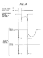
- Figure 10 shows the ionization current waveforms during misfire and normal combustion, in which the discharge is produced by a high voltage of negative polarity.
- the ionization current waveform during normal combustion i.e., when ions are produced, spikes instantaneously in the minus direction just after the discharge across the ignition plug electrodes (as seen at A in the drawing), thereafter continues to flow in proportion to the volume or number of ions produced, and eventually returns to a given level.
- misfire i.e., when ions are not produced
- the waveform spikes instantaneously in the minus direction just after the end of discharge (as seen at A' in the drawing) and then immediately returns to the given level.
- a widely used method of detecting engine misfire has therefore been to detect the ionization current (current waveform) occurring during the combustion stroke using the ignition plug, more exactly the electrodes thereof, as a probe for detecting ionization current, and comparing the detected value with a prescribed value, as taught by, for example, Japanese Laid-open Patent Application No. Hei 5(1993)-99956.
- the present invention was accomplished to overcome the foregoing problems and has as an object to provide a misfire detection system for internal combustion engines that is unaffected by fluctuation in ignition coil discharge period, various kinds of noise and the like, and can therefore ensure accurate misfire detection by preventing erroneous detection (erroneous discrimination) owing to such causes.
- this invention provides a system for detecting misfire for an internal combustion engine having an ignition plug, installed to face into a combustion chamber of a cylinder of the engine and connected to an ignition coil, which produces spark discharge when supplied with discharge current from the ignition coil to ignite air-fuel mixture in the combustion chamber; including: a current detection circuit which detects ionization current, that flows following the discharge current, during a period; a misfire detector which detects occurrence of misfire of the engine based on the detected current; and a processing delay circuit which inputs at least one of the discharge current and the ionization current and based on the inputted current, delays starting of the period by a time point which is not earlier than termination of the discharge current.
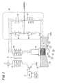
- Figure 1 is a partial circuit diagram of the engine misfire detection system according to the embodiment, showing an ignition circuit for producing a spark in an ignition plug and an ionization current detector for detecting ionization current produced during combustion.
- the engine misfire detection system comprises an ignition coil 10 whose primary side (low-voltage side) coil 10a is connected at one end to an electric power source (onboard battery) 12 and at the other to ground through a power transistor 16 that is switched by an ignition signal from an ECU (electronic control unit) 14.
- ECU electronic control unit
- One end of the secondary side (high-voltage side) coil 10b of the ignition coil 10 is connected to the center electrode 24a of an ignition plug 24 installed to face into a combustion chamber 22 of each cylinder 20 (only one indicated as the corresponding part of a cylinder head 18) of a multi-cylinder internal combustion engine (only illustrated by the cylinder 20 etc.).
- the ground (outer) electrode 24b of the ignition plug 24 is grounded through the cylinder head 18. Following the completion of discharge, the ignition plug 24 also functions as a probe for detecting ionization current. This will be explained in detail later.
- the other end of the secondary coil 10b of the ignition coil 10 is connected to an ionization current detector (current detection circuit) 30.
- the ionization current detector 30 comprises a parallel connection of an ionization current detection capacitor 32 charged in the illustrated polarity by discharge current and a Zener diode 34 that regulates the charging voltage of the ionization current detection capacitor 32, a detection resistor 36 through which the ionization current detection capacitor 32 is connected to ground, and a diode 38 for preventing reverse current flow through which the Zener diode 34 is connected to ground.
- the ECU 14 comprises a microcomputer. It is inputted with the outputs of a group of sensors, including a crank angle sensor 40 that is installed near the crankshaft or camshaft (neither shown) of the engine and outputs a signal representing the TDC position and subdivided crank angles thereof of the individual cylinders, a manifold absolute pressure sensor 42 that outputs a signal representing the absolute pressure (PBA) in the air intake pipe, and other sensors not shown in the drawing.
- a crank angle sensor 40 that is installed near the crankshaft or camshaft (neither shown) of the engine and outputs a signal representing the TDC position and subdivided crank angles thereof of the individual cylinders
- PBA absolute pressure
- the air-fuel mixture (more precisely the combustion gas produced by normal burning of the air-fuel mixture) ionizes.
- the ions produced migrate owing to the effect of the bias voltage of the ionization current detection capacitor 32 and their resulting presence between the electrodes of the ignition plug 24 lowers the electrical resistance between the electrodes.
- ionization current flows through the path of the ionization current detection capacitor 32 ⁇ secondary coil 10b ⁇ ignition plug 24, as indicated by the alternate long and two short dashed line in Figure 1.
- the ionization current occurring at this time changes the voltage drop across the detection resistor 36.
- the ionization current detector 30 outputs this voltage change, i.e., the ionization current waveform, to a waveform converter explained later.
- the ECU 14 calculates an ignition timing based on the inputted values from the crank angle sensor 40, manifold absolute pressure sensor 42 and other sensors, and produces an ignition command current pulse in such a way that ignition occurs at the calculated timing. It also discriminates whether or not the engine is in a misfire state (conducts misfire detection) based on an integral value (voltage) outputted by an integrator explained later.
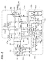
- Figure 2 is a circuit diagram schematically showing the overall configuration of the misfire detection system for internal combustion engines according to this embodiment of the present invention. Part of the ignition circuit is omitted from Figure 2 for convenience of illustration.
- Figure 3 is a block diagram representing the circuit of Figure 2 in block form.
- the ionization current waveform detected in the current detector 30 is forwarded to the waveform converter (now assigned with reference numeral 50) that subjects the waveform to polarity-reversal and voltage-reduction processing.
- the ionization current waveform subjected to polarity-reversal and voltage-reduction in the waveform converter 50 is passed through a high-pass filter 60 to remove its low-frequency components and then input to an integrator 70 that effects integration processing to determine the time integral of the ionization current. As a result, there obtained an output signal proportional to the time integral.
- the ionization current waveform after polarity reversal and voltage reduction in the waveform converter 50 is also sent to a gate width setting unit 80.
- the gate width setting unit 80 passes the ionization current waveform through an internal low-pass filter to attenuate frequency band output (noise) other than the ionization current. It also sets or determining the width of a gate (ionization current integration period) in proportion to the period of ionization current occurrence, thereby setting the period of integration by the integrator 70.
- a processing delay unit (circuit) 90 delays (masks) the integration start time set by the gate width setting unit 80 to a time point that enables avoidance of the effect of inductive noise.
- a gate on/off unit 100 operates to turn the input of the ionization current waveform to the integrator 70 ON and OFF in accordance with the integration period and integration start time set or determined by the gate width setting unit 80 and processing delay unit 90.
- the integration by the integrator 70 is thus limited to a desired period (gate), i.e., only the period during which ionization current occurs.
- the integral value calculated over the integration period (the gate width) by the integrator 70 is reset by an integral reset unit 110 when the next ignition command current pulse is sent to the ignition coil.
- the integration period which defines the ionization current detection period, is set or determined in accordance with the ionization current occurrence period and, in addition, its start time is delayed (masked) to a time point that makes the detection safe from the influence of inductive noise.
- the ionization current detector 30 detects the ionization current waveform (more precisely the voltage waveform) produced by air-fuel mixture combustion and the detected ionization current waveform is outputted to the waveform converter 50.
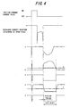
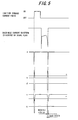
- Figures 4 and 5 are time charts showing outputs (detected current waveforms and pulses) in the engine misfire detection system of the present embodiment.
- the time chart of Figure 4 is for the case of normal combustion.
- One for the case of misfire is shown in Figure 5.
- the symbols a , b , c ..., g in Figures 4 and 5 indicate the outputs at a , b , c ..., g in Figure 2.
- the ionization current waveform detected by the ionization current detector 30 (specifically the detection resistor 36), i.e., the current waveform at the point designated a in Figure 2, spikes instantaneously in the minus direction owing to inductive noise just after the discharge across the gap of the ignition plug 24, current thereafter continues to flow in proportion to the volume or number of ions produced, and eventually returns to a given level.
- the waveform spikes instantaneously just after the end of discharge and then immediately returns to the given level.
- the ionization current waveform detected in the ionization current detector 30 is forwarded to the waveform converter 50, where it is reversed in polarity and lowered in voltage, and is then sent through the high-pass filter 60 to the integrator 70.
- the ionization current waveform after polarity reversal and voltage reduction in the waveform converter 50 is also sent to the gate width setting unit 80.
- the gate width setting unit 80 passes the ionization current waveform through an internal low-pass filter to attenuate frequency band output other than the ionization current, as mentioned earlier.
- the filtered output specifically the current waveform at the point designated b in Figure 2 (shown at b in Figures 4 and 5) is inputted to the negative (inverting) terminal of a gate width setting comparator 82.
- the positive (non-inverting) terminal of the gate width setting comparator 82 is connected to a reference voltage supply circuit 800 (comprising two resistors 800a, 800b provided between the power source 12 and the ground) at a position divided by the two resistors and is constantly inputted with a reference voltage or value (shown at c in Figures 4 and 5).
- the negative (inverting) terminal of the comparator 82 is connected to the output from the waveform converter 50 through capacitors CL1, CL2 and a comparator, as illustrated.
- the two voltages are compared and when the output from the low-pass filter (ionization current waveform) is higher, the output of the gate width setting comparator 82, i.e., the output pulse at the point designated d in Figure 2 (shown at d in Figures 4 and 5) is made Low. In other words, the output pulse of the gate width setting comparator 82 is made High when the reference voltage is higher.
- the Low pulse output period of the gate width setting comparator 82 is the gate width (which corresponds to the period of the integration performed in the integrator 70 and thus to the ionization current detection period for detecting misfire). Since the gate width setting unit 80 thus sets the gate width based on the ionization current waveform (the period of ionization current occurrence), currents that arise outside the period of ionization current occurrence owing to various kinds of noise and other causes are not detected and are therefore prevented from having an effect on the misfire detection. As a result, false misfire detection (erroneous discrimination) owing to such currents is prevented and accurate misfire detection is ensured.
- the output pulse of the gate width setting unit 80 is sent to the processing delay unit 90.
- the processing delay unit 90 delays the integration start time, i.e., sets or determines the masking period at the beginning of the gate width.
- the fall time point of the output pulse from the gate width setting unit 80 (at the time of Low pulse output) is delayed by the charging/discharging of a processing delay capacitor 92.
- the High period of the output pulse is extended to obtain a current waveform at the point designated e in Figure 2 like that shown at e in Figures 4 and 5.
- the so-obtained current waveform is inputted to the positive (non-inverting) terminal of a processing delay comparator 94.
- the negative (inverting) terminal of the comparator 94 is connected to reference voltage supply circuit 900 (comprising two resistors 900a, 900b provided between the power source 12 and the ground) at a position divided by the two resistors and is inputted with a reference voltage or value (shown at f in Figures 4 and 5).
- the two voltages are compared and when the current waveform at e in Figure 2 is lower than the reference voltage, the output of the processing delay comparator 94, i.e., the output pulse g in Figure 2 (shown at g in Figures 4 and 5), is made Low.
- the fall time point of the output pulse finally obtained from the processing delay unit 90 is delayed by a certain time from the start of ionization current occurrence.
- the fall time point of the output pulse is delayed by a certain time from the termination of current discharge, since the ionization current occurrence follows immediately after the termination of current discharge.
- the period (gate) is delayed by a time point which is not earlier than the termination of the discharge current.
- the input to the integrator 70 of the ionization current waveform outputted from the high-pass filter 60 is turned ON and OFF by ON/OFF operating a FET (field effect transistor) 102 of a gate on/off unit 100 based on this output pulse whose fall time point has been delayed.
- the integrator 70 time-integrates the ionization current input thereto in the foregoing manner and sends an output signal proportional to the time integral, namely, the voltage value of an integration capacitor 72, to the ECU 14.
- the ECU 14 compares the voltage value with a certain preset value to discriminate whether or not the engine is in a misfire state (conducts misfire detection).
- the delay time varies with the capacity (indicative of time constant) of the processing delay capacitor 92 and the magnitude of the reference voltage indicated at f in Figures 4 and 5. Therefore, by appropriately setting or determining one or both of these values, the length of the delay time can be set to one that eliminates the influence of inductive noise. Since this makes it possible reliably mask the region of the ionization current waveform outputted from the high-pass filter 60 that corresponds to the period of inductive noise occurrence, the inductive noise can be prevented from having an adverse effect on the misfire detection. As a result, false misfire detection (discrimination) caused by inductive noise can be prevented to achieve still more accurate misfire detection.
- the voltage of the integration capacitor 72 is reset when the next ignition command current pulse is sent to the ignition coil as mentioned above, by turning on a switch 112 of the integral reset unit 110 so as to discharge the integration capacitor 72.
- the starting of the gate is delayed by a time which is not earlier than the termination of the discharge current and the gate width is set based on the waveform of the ionization current (period of ionization current occurrence, i.e., the termination of current discharge) so as to avoid detection of currents produced by various kinds of noise occurring outside the period of ionization current occurrence.
- the ionization current period of ionization current occurrence, i.e., the termination of current discharge
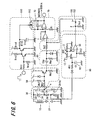
- Figure 6 is a view, similar to Figure 2, but showing the configuration of a misfire detection system for internal combustion engines according to a second embodiment of the present invention.
- the system is configured such that the gate width setting unit 80 is incorporated into the processing delay unit 9 and the current detector 30 is modified to output the discharge current (produced in the secondary coil 10b when the current flow through the primary coil 10a is discontinued) to the processing delay unit 90 in such a way that the integration start time is delayed (masked) to a time point from the termination of the discharge current, more precisely by a time point which is not earlier than the termination of the discharge current that enables avoidance of the effect of inductive noise.
- the diode 38 is grounded through a secondary detection resistor 36b, and at a point 39 therebetween, the line is branched in such a manner that the voltage at the junction is outputted and is sent, via the processing delay capacitor 92, to the positive (non-inverting) terminal of the processing delay comparator 94 of the processing delay unit 90.
- the negative (inverting) terminal of the comparator 94 is connected to the reference voltage supply circuit 900 at a position divided by the two resistors 900a, 900b and is constantly inputted with the reference voltage.
- the fall time point of the discharge current waveform (at the time of Low pulse output) can be delayed by the charging/discharging of the processing delay capacitor 92.
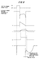
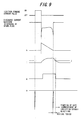
- the High period of the output pulse is extended to obtain a current waveform at the point designated g in Figure 7 like that shown at g in Figures 8 and 9, beyond the termination of the discharge current at the point 39 as shown at h in the figures.
- the processing delay capacitor 92 and the reference voltage supply circuit 900 now constitutes the processing delay unit 90.
- the discharge current waveform detected at the point (junction) 39 is inputted to the positive (non-inverting terminal) of the processing delay comparator 92 through a diode and a resistor Rt1.
- the current waveform at the point designated i in Figure 7 is shown at i in Figures 8 and 9, and compared with the reference voltage input to the negative (inverting) terminal of the comparator 94 is supplied with the reference voltage (shown at j in Figures 6, 8 and 9).
- the output of the comparator 94 i.e., the output pulse at the point designated g in Figure 6 is made Low, whose pulse output period (pulse) defines the gate width (which corresponds to the period of the integration performed in the integrator 70 and thus to the ionization current detection period for detecting misfire.
- the delay time varies with the capacity (indicative of time constant) of the processing delay capacitor 92 and the magnitude of the reference voltage indicated at j in Figures 8 and 9. Therefore, by appropriately setting or determining one or both of these values, the length of the delay time can be set to one that eliminates the influence of inductive noise. Since this makes it possible reliably mask the region of the ionization current waveform output from the high-pass filter 60 that corresponds to the period of inductive noise occurrence, the inductive noise can be prevented from having an adverse effect on the misfire detection. As a result, false misfire detection (discrimination) caused by inductive noise can be prevented to achieve still more accurate misfire detection.
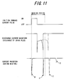
- the gate on/off unit 100 since the gate on/off unit 100 only determines the opening of the gate and the gait is left open until it is reset by the next ignition command current pulse, the system cannot exclude the detection of various kinds of noise (such as indicated at D in Figure 11) occurring at times other than during the masking period. Except for the above, the rest of the configuration including the misfire detection by the integrated ionization current is the same as that of the first embodiment.
- the first and second embodiments are thus configured to have a system for detecting misfire for an internal combustion engine having an ignition plug (24), installed to face into a combustion chamber (22) of a cylinder (20) of the engine and connected to an ignition coil (10), which produces spark discharge when supplied with discharge current from the ignition coil to ignite air-fuel mixture in the combustion chamber; including: a current detection circuit (current detector 30) which detects ionization current, that flows following the discharge current, during a period (gate); and a misfire detector (ECU 14) which detects occurrence of misfire of the engine based on the detected current.
- a current detection circuit current detector 30
- ECU 14 misfire detector
- the characterizing feature is that;the system includes: a processing delay circuit (ECU 14, unit 90) which inputs at least one of the discharge current and the ionization current and based on the inputted current, delays starting of the period by a time point which is not earlier than termination of the discharge current.
- a processing delay circuit ECU 14, unit 90
- the processing delay circuit includes; a comparator (94) which inputs the current to compares with a reference value (voltage) and produces an output indicative of at least starting of the period, and a capacitor (92) provided before the comparator which delays inputting of the current to the comparator such that the starting of the period is delayed by the time.
- the processing delay circuit includes; a comparator (94) which inputs the current to compares with a reference value (voltage) and produces an output indicative of at least starting of the period, and a reference value (voltage) supply circuit (800, 900) which varies the reference value (voltage) to delay producing of the output of the comparator such that the starting of the period is delayed by the time.
- the system further including a comparator (82) which inputs the ionization current to be compared with a reference value (voltage) and produces the output indicative of the starting and ending of the period (gate).
- the comparator (94) inputs the discharge current and produces the output indicative of the starting of the period (gate).
- the current detection circuit more precisely the integrator 70 includes an integration capacitor (72) to be charged by the ionization current, and the misfire detector detects the occurrence of misfire of the engine based on an output of the integration capacitor.
- the engine misfire detection system is configured to delay the start of the integration period by a prescribed period (the masking period) from the start of the period of ionization current occurrence, waveforms during the time of inductive noise occurrence can be reliably masked and prevented from exerting any adverse effect. False misfire detection caused by such a waveform can therefore be prevented to enable still more accurate detection of misfire.
- a processing delay circuit (unit 90) which inputs at least one of the discharge current and the ionization current and based on the inputted current, delays starting of the period by a time point which is not earlier than termination of the discharge current.
Landscapes
- Engineering & Computer Science (AREA)
- Chemical & Material Sciences (AREA)
- Combustion & Propulsion (AREA)
- Physics & Mathematics (AREA)
- General Physics & Mathematics (AREA)
- Mechanical Engineering (AREA)
- General Engineering & Computer Science (AREA)
- Ignition Installations For Internal Combustion Engines (AREA)
- Combined Controls Of Internal Combustion Engines (AREA)
Applications Claiming Priority (4)
| Application Number | Priority Date | Filing Date | Title |
|---|---|---|---|
| JP2000387040 | 2000-12-20 | ||
| JP2000387040A JP3507793B2 (ja) | 2000-12-20 | 2000-12-20 | 内燃機関の失火検出装置 |
| JP2001317676A JP3704303B2 (ja) | 2001-10-16 | 2001-10-16 | 内燃機関の失火検出装置 |
| JP2001317676 | 2001-10-16 |
Publications (3)
| Publication Number | Publication Date |
|---|---|
| EP1217207A2 true EP1217207A2 (fr) | 2002-06-26 |
| EP1217207A3 EP1217207A3 (fr) | 2004-04-07 |
| EP1217207B1 EP1217207B1 (fr) | 2006-05-24 |
Family
ID=26606181
Family Applications (1)
| Application Number | Title | Priority Date | Filing Date |
|---|---|---|---|
| EP01130308A Expired - Lifetime EP1217207B1 (fr) | 2000-12-20 | 2001-12-19 | Système pour détecter des ratés d'allumage pour un moteur à combustion interne |
Country Status (3)
| Country | Link |
|---|---|
| US (1) | US6803765B2 (fr) |
| EP (1) | EP1217207B1 (fr) |
| DE (1) | DE60119879T8 (fr) |
Cited By (7)
| Publication number | Priority date | Publication date | Assignee | Title |
|---|---|---|---|---|
| GB2396187A (en) * | 2002-11-01 | 2004-06-16 | Visteon Global Tech Inc | I.c. engine in-cylinder ionization detection system with ionization detection circuit and ignition coil driver circuit integrated into a single package |
| FR2859506A1 (fr) * | 2003-09-04 | 2005-03-11 | Visteon Global Tech Inc | Procede de conditionnement d'un signal d'ionisation d'un moteur a combustion interne |
| DE10350855B4 (de) * | 2002-11-01 | 2012-01-19 | Visteon Global Technologies Inc. | Zündspule mit integrierter Spulentreiber- und Ionisierungserfassungs-Schaltung |
| CN102418643A (zh) * | 2011-08-08 | 2012-04-18 | 同济大学 | 用于火花点燃式发动机失火控制的装置及方法 |
| WO2013119178A1 (fr) * | 2012-02-09 | 2013-08-15 | Sem Ab | Moteur avec détection des ratés d'allumage pour des véhicules utilisant des carburants alternatifs |
| DE102006023500B4 (de) * | 2005-12-16 | 2013-09-26 | Mitsubishi Denki K.K. | Zündvorrichtung für einen Verbrennungsmotor |
| GB2592239A (en) * | 2020-02-20 | 2021-08-25 | Delphi Automotive Systems Lux | Method of controlling and monitoring spark ignition systems |
Families Citing this family (5)
| Publication number | Priority date | Publication date | Assignee | Title |
|---|---|---|---|---|
| US7690352B2 (en) | 2002-11-01 | 2010-04-06 | Visteon Global Technologies, Inc. | System and method of selecting data content of ionization signal |
| US7472687B2 (en) * | 2002-11-01 | 2009-01-06 | Visteon Global Technologies, Inc. | System and method for pre-processing ionization signal to include enhanced knock information |
| JP6063677B2 (ja) * | 2012-09-06 | 2017-01-18 | ローム株式会社 | 信号検出回路及びイグナイタ |
| US11193432B2 (en) | 2016-12-29 | 2021-12-07 | Cummins Inc. | Gated ionization current supply voltage |
| PE20221432A1 (es) * | 2019-11-27 | 2022-09-21 | Tvs Motor Co Ltd | Deteccion de fallas de encendido de un motor de combustion interna |
Citations (1)
| Publication number | Priority date | Publication date | Assignee | Title |
|---|---|---|---|---|
| JPH0599956A (ja) | 1991-10-04 | 1993-04-23 | Mitsubishi Electric Corp | 内燃機関のイオン電流検出装置 |
Family Cites Families (12)
| Publication number | Priority date | Publication date | Assignee | Title |
|---|---|---|---|---|
| US533716A (en) * | 1895-02-05 | Machine for perforating and grading fruit | ||
| JP2721604B2 (ja) * | 1991-09-30 | 1998-03-04 | 株式会社日立製作所 | 燃焼状態診断装置 |
| US5337716A (en) * | 1992-02-04 | 1994-08-16 | Mitsubishi Denki Kabushiki Kaisha | Control apparatus for internal combustion engine |
| US5534781A (en) * | 1994-08-15 | 1996-07-09 | Chrysler Corporation | Combustion detection via ionization current sensing for a "coil-on-plug" ignition system |
| JPH08200196A (ja) * | 1995-01-31 | 1996-08-06 | Hitachi Ltd | 内燃機関の失火検出装置および失火検出方法 |
| US5777216A (en) * | 1996-02-01 | 1998-07-07 | Adrenaline Research, Inc. | Ignition system with ionization detection |
| JP3129403B2 (ja) * | 1997-05-15 | 2001-01-29 | トヨタ自動車株式会社 | イオン電流検出装置 |
| US5896842A (en) * | 1997-06-05 | 1999-04-27 | General Motors Corporation | Closed-loop ignition timing control |
| US5778855A (en) * | 1997-07-03 | 1998-07-14 | Ford Global Technologies, Inc. | Combustion stability control for lean burn engines |
| WO1999031384A1 (fr) * | 1997-12-12 | 1999-06-24 | Temic Telefunken Microelectronic Gmbh | Procede de mesure de flux ionique dans des moteurs a combustion interne, et dispositif de mesure de flux ionique |
| DE19915088A1 (de) * | 1999-04-01 | 2000-10-05 | Bosch Gmbh Robert | Verfahren und Vorrichtung zur Auswertung von Ionenstromsignalen zur Beurteilung von Verbrennungsvorgängen |
| US6360587B1 (en) * | 2000-08-10 | 2002-03-26 | Delphi Technologies, Inc. | Pre-ignition detector |
-
2001
- 2001-12-19 DE DE60119879T patent/DE60119879T8/de not_active Expired - Fee Related
- 2001-12-19 EP EP01130308A patent/EP1217207B1/fr not_active Expired - Lifetime
- 2001-12-20 US US10/022,869 patent/US6803765B2/en not_active Expired - Fee Related
Patent Citations (1)
| Publication number | Priority date | Publication date | Assignee | Title |
|---|---|---|---|---|
| JPH0599956A (ja) | 1991-10-04 | 1993-04-23 | Mitsubishi Electric Corp | 内燃機関のイオン電流検出装置 |
Cited By (13)
| Publication number | Priority date | Publication date | Assignee | Title |
|---|---|---|---|---|
| GB2396187A (en) * | 2002-11-01 | 2004-06-16 | Visteon Global Tech Inc | I.c. engine in-cylinder ionization detection system with ionization detection circuit and ignition coil driver circuit integrated into a single package |
| GB2396187B (en) * | 2002-11-01 | 2005-03-23 | Visteon Global Tech Inc | A device for reducing the part count and package size of an in-cylinder ionization detection system |
| US7063079B2 (en) | 2002-11-01 | 2006-06-20 | Visteon Global Technologies, Inc. | Device for reducing the part count and package size of an in-cylinder ionization detection system by integrating the ionization detection circuit and ignition coil driver into a single package |
| DE10350855B4 (de) * | 2002-11-01 | 2012-01-19 | Visteon Global Technologies Inc. | Zündspule mit integrierter Spulentreiber- und Ionisierungserfassungs-Schaltung |
| FR2859506A1 (fr) * | 2003-09-04 | 2005-03-11 | Visteon Global Tech Inc | Procede de conditionnement d'un signal d'ionisation d'un moteur a combustion interne |
| US7197913B2 (en) | 2003-09-04 | 2007-04-03 | Visteon Global Technologies, Inc. | Low cost circuit for IC engine diagnostics using ionization current signal |
| DE102006023500B4 (de) * | 2005-12-16 | 2013-09-26 | Mitsubishi Denki K.K. | Zündvorrichtung für einen Verbrennungsmotor |
| CN102418643B (zh) * | 2011-08-08 | 2013-06-26 | 同济大学 | 用于火花点燃式发动机失火控制的装置及方法 |
| CN102418643A (zh) * | 2011-08-08 | 2012-04-18 | 同济大学 | 用于火花点燃式发动机失火控制的装置及方法 |
| WO2013119178A1 (fr) * | 2012-02-09 | 2013-08-15 | Sem Ab | Moteur avec détection des ratés d'allumage pour des véhicules utilisant des carburants alternatifs |
| US9810191B2 (en) | 2012-02-09 | 2017-11-07 | Sem Ab | Engine for vehicle using alternative fuels |
| GB2592239A (en) * | 2020-02-20 | 2021-08-25 | Delphi Automotive Systems Lux | Method of controlling and monitoring spark ignition systems |
| GB2592239B (en) * | 2020-02-20 | 2022-06-22 | Delphi Automotive Systems Lux | Method of controlling and monitoring spark ignition systems |
Also Published As
| Publication number | Publication date |
|---|---|
| EP1217207A3 (fr) | 2004-04-07 |
| DE60119879D1 (de) | 2006-06-29 |
| EP1217207B1 (fr) | 2006-05-24 |
| US6803765B2 (en) | 2004-10-12 |
| DE60119879T2 (de) | 2006-11-30 |
| DE60119879T8 (de) | 2007-05-24 |
| US20020093339A1 (en) | 2002-07-18 |
Similar Documents
| Publication | Publication Date | Title |
|---|---|---|
| US4987771A (en) | Misfire detection device for an internal combustion engine | |
| US5785020A (en) | Combustion state detecting apparatus for an internal-combustion engine | |
| JP2602075B2 (ja) | 内燃機関の点火システムにおける電離電流を検出する方法および装置 | |
| EP1217207B1 (fr) | Système pour détecter des ratés d'allumage pour un moteur à combustion interne | |
| KR960004282B1 (ko) | 내연기관의 녹킹 검출장치 | |
| US6092015A (en) | Combustion state detecting apparatus for an internal-combustion engine | |
| US5226394A (en) | Misfire-detecting system for internal combustion engines | |
| US5606118A (en) | System and method for detecting misfire in an internal combustion engine | |
| US5349299A (en) | Fuel supply misfire-detecting system for internal combustion engines | |
| JP3783823B2 (ja) | 内燃機関のノック制御装置 | |
| US6155241A (en) | Method for identifying knocking combustion in an internal combustion engine with an alternating current ignition system | |
| JP2003314352A (ja) | 内燃機関の失火検出装置 | |
| US6691555B2 (en) | Firing state discrimination system for internal combustion engines | |
| US4515132A (en) | Ionization probe interface circuit with high bias voltage source | |
| US5327090A (en) | Misfire-detecting system for an internal combustion engine which detects a misfire due to the fuel supply system | |
| JP3633580B2 (ja) | 内燃機関の失火検出装置 | |
| JP3874800B2 (ja) | 圧縮行程にある燃焼エンジンの燃焼室を特定する方法、燃焼エンジンを始動する方法および燃焼エンジンのための装置 | |
| US7251571B2 (en) | Methods of diagnosing open-secondary winding of an ignition coil using the ionization current signal | |
| JPS6368774A (ja) | 内燃機関用スパ−クプラグのプレイグニシヨン検出装置 | |
| JP3704303B2 (ja) | 内燃機関の失火検出装置 | |
| JP3507793B2 (ja) | 内燃機関の失火検出装置 | |
| KR20010042831A (ko) | 4-행정 오토 엔진에서 이온 전류 측정을 이용한 위상인식을 위한 방법 및 장치 | |
| JP2003184635A (ja) | イオン電流を用いたエンジンの失火検出装置及び該装置に用いられるプログラムを記録した記録媒体 | |
| JP3577217B2 (ja) | 内燃機関の点火プラグくすぶり検出装置 | |
| JP2003286892A (ja) | 内燃機関の失火検出装置 |
Legal Events
| Date | Code | Title | Description |
|---|---|---|---|
| PUAI | Public reference made under article 153(3) epc to a published international application that has entered the european phase |
Free format text: ORIGINAL CODE: 0009012 |
|
| 17P | Request for examination filed |
Effective date: 20011219 |
|
| AK | Designated contracting states |
Kind code of ref document: A2 Designated state(s): AT BE CH CY DE DK ES FI FR GB GR IE IT LI LU MC NL PT SE TR |
|
| AX | Request for extension of the european patent |
Free format text: AL;LT;LV;MK;RO;SI |
|
| PUAL | Search report despatched |
Free format text: ORIGINAL CODE: 0009013 |
|
| AK | Designated contracting states |
Kind code of ref document: A3 Designated state(s): AT BE CH CY DE DK ES FI FR GB GR IE IT LI LU MC NL PT SE TR |
|
| AX | Request for extension of the european patent |
Extension state: AL LT LV MK RO SI |
|
| AKX | Designation fees paid |
Designated state(s): DE GB |
|
| 17Q | First examination report despatched |
Effective date: 20041206 |
|
| GRAP | Despatch of communication of intention to grant a patent |
Free format text: ORIGINAL CODE: EPIDOSNIGR1 |
|
| GRAS | Grant fee paid |
Free format text: ORIGINAL CODE: EPIDOSNIGR3 |
|
| GRAA | (expected) grant |
Free format text: ORIGINAL CODE: 0009210 |
|
| AK | Designated contracting states |
Kind code of ref document: B1 Designated state(s): DE GB |
|
| REG | Reference to a national code |
Ref country code: GB Ref legal event code: FG4D |
|
| REF | Corresponds to: |
Ref document number: 60119879 Country of ref document: DE Date of ref document: 20060629 Kind code of ref document: P |
|
| PGFP | Annual fee paid to national office [announced via postgrant information from national office to epo] |
Ref country code: GB Payment date: 20061213 Year of fee payment: 6 |
|
| PGFP | Annual fee paid to national office [announced via postgrant information from national office to epo] |
Ref country code: DE Payment date: 20061214 Year of fee payment: 6 |
|
| PLBE | No opposition filed within time limit |
Free format text: ORIGINAL CODE: 0009261 |
|
| STAA | Information on the status of an ep patent application or granted ep patent |
Free format text: STATUS: NO OPPOSITION FILED WITHIN TIME LIMIT |
|
| 26N | No opposition filed |
Effective date: 20070227 |
|
| GBPC | Gb: european patent ceased through non-payment of renewal fee |
Effective date: 20071219 |
|
| PG25 | Lapsed in a contracting state [announced via postgrant information from national office to epo] |
Ref country code: DE Free format text: LAPSE BECAUSE OF NON-PAYMENT OF DUE FEES Effective date: 20080701 |
|
| PG25 | Lapsed in a contracting state [announced via postgrant information from national office to epo] |
Ref country code: GB Free format text: LAPSE BECAUSE OF NON-PAYMENT OF DUE FEES Effective date: 20071219 |