EP1218903B1 - Verbesserter elektroschalter mit fühlbarem effekt und einen einzigen schaltglied - Google Patents
Verbesserter elektroschalter mit fühlbarem effekt und einen einzigen schaltglied Download PDFInfo
- Publication number
- EP1218903B1 EP1218903B1 EP00964265A EP00964265A EP1218903B1 EP 1218903 B1 EP1218903 B1 EP 1218903B1 EP 00964265 A EP00964265 A EP 00964265A EP 00964265 A EP00964265 A EP 00964265A EP 1218903 B1 EP1218903 B1 EP 1218903B1
- Authority
- EP
- European Patent Office
- Prior art keywords
- contact
- contact plate
- electrical switch
- switch according
- blades
- Prior art date
- Legal status (The legal status is an assumption and is not a legal conclusion. Google has not performed a legal analysis and makes no representation as to the accuracy of the status listed.)
- Expired - Lifetime
Links
- 230000000694 effects Effects 0.000 title claims description 5
- 230000000087 stabilizing effect Effects 0.000 claims description 18
- 239000004020 conductor Substances 0.000 claims description 4
- 230000000994 depressogenic effect Effects 0.000 abstract 1
- 239000002184 metal Substances 0.000 description 4
- 230000002093 peripheral effect Effects 0.000 description 4
- 238000005192 partition Methods 0.000 description 3
- 230000000295 complement effect Effects 0.000 description 2
- 230000035807 sensation Effects 0.000 description 2
- 238000005452 bending Methods 0.000 description 1
- 238000010276 construction Methods 0.000 description 1
- 238000000034 method Methods 0.000 description 1
- 238000010619 multiway switching Methods 0.000 description 1
- 239000012811 non-conductive material Substances 0.000 description 1
- 238000007789 sealing Methods 0.000 description 1
Images


Classifications
-
- H—ELECTRICITY
- H01—ELECTRIC ELEMENTS
- H01H—ELECTRIC SWITCHES; RELAYS; SELECTORS; EMERGENCY PROTECTIVE DEVICES
- H01H13/00—Switches having rectilinearly-movable operating part or parts adapted for pushing or pulling in one direction only, e.g. push-button switch
- H01H13/02—Details
- H01H13/26—Snap-action arrangements depending upon deformation of elastic members
- H01H13/48—Snap-action arrangements depending upon deformation of elastic members using buckling of disc springs
Definitions
- the present invention relates to an electrical switch having a tactile effect.
- the invention relates more particularly to a very small switch of the type comprising a contact-carrying support which defines a housing in the bottom of which at least two fixed electrical contacts are placed and which houses an overall dome-shaped tripping member which is elastically deformable, from a stable rest state, due to the action of an actuating member, especially a pusher, which acts on the central part of the tripping member in a direction approximately perpendicular to the bottom of the housing, for the purpose of establishing electrical connection between the two fixed contacts.
- the sudden change of state of the tripping member gives its user, who acts directly or indirectly on the actuating pusher, a tactile sensation of the change of state of the tripping member and therefore the change of the switch.
- the tripping member is, for example, made in the form of a domed disc or of an element having a rectangular outline of pyramidal overall shape.
- the switch is of the type comprising:
- the intermediate contact plate is interposed vertically between the tripping member and the bottom of the housing, and the actuating member acts, directly or indirectly, on the tripping member.
- a simple tripping action on the single tripping member thus makes it possible to electrically connect the output terminals, almost simultaneously, so as to ensure switching of several electrical channels connected to the output terminals of the switch, for example three channels.
- the central part of the monostable-type tripping member "strikes" the free ends of the contact blades, which flex elastically with a relatively large deformation travel.
- the aim of the invention is to propose another example of a construction of an electrical switch of the above-mentioned type which makes it possible to improve its reliability and to further reduce its dimensions.
- the invention provides a switch characterized in that the tripping member is vertically interposed between the bottom of the housing and a central part of the contact plate so as to define a high vertical position of the contact plate corresponding to its rest state, and in that the contact plate comprises at least one pair of elastically deformable opposed stabilizing branches which extend from the central part and the free ends of which bear against the bottom of the housing.
- the tripping member no longer participates directly in establishing the electrical connections between the contact blades and their associated fixed contacts which result from the vertical downward travel of the contact plate.
- the contact blades are only slightly flexed at the end of travel.
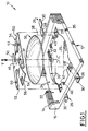
- Figure 1 shows a contact-carrying support which, according to a known general design, essentially consists of a body or casing 12 which is moulded in an insulating plastic and which in this case is of rectangular parallelepipedal overall shape.
- the body 12 is produced by overmoulding over conducting elements which constitute, in the example illustrated in the figures, a series of four fixed electrical contacts 26.
- the switch also comprises actuating means and an upper closure plate of known design (not shown).
- the fixed contacts 26 here are four in number, which lie longitudinally parallel to one another and are associated in pairs of fixed contacts 26 aligned longitudinally two by two in the bottom 25 of the housing 22.
- the upper faces of the inner contact ends 28 lie in the same plane parallel to the plane at the bottom 25.
- the switch 10 includes a tripping member 36, designed to be housed in the housing 22, this member being an element made from a sheet, for example metal sheet, which has an overall dome shape in the form of a spherical cap, the circular lower outline 38 of which has a shape and dimensions which are complementary to those of a cavity 32 made in the bottom of the housing and which is bounded by a peripheral part 34 of additional thickness and by four longitudinally oriented vertical partitions 40 adjacent to the inner ends 28 of the fixed contacts 26, the free ends 42 of which partitions 40 participate in the positioning of the monostable dome 36 by engaging with its lower edge 38.
- a tripping member 36 designed to be housed in the housing 22, this member being an element made from a sheet, for example metal sheet, which has an overall dome shape in the form of a spherical cap, the circular lower outline 38 of which has a shape and dimensions which are complementary to those of a cavity 32 made in the bottom of the housing and which is bounded by a peripheral part 34 of additional thickness and by four longitudinally
- the general concavity of the tripping member 36 is turned towards the bottom 25 and the tripping member can be deformed, in opposition to its intrinsic elasticity, in a vertical tripping direction V and from its stable rest state illustrated in the Figures 1, 2 and 3 to an unstable trip state illustrated in Figures 5 and 6.
- a tripping member 36 changes state suddenly, beyond a defined tripping travel, so as to impart a tactile sensation of the tripping to the user.
- a contact plate 44 is interposed vertically between the actuating member (not shown) and the tripping member 36.
- the contact plate 44 is a plate made of a conductive material which is, for example, produced by cutting it out of a thin metal sheet in order to give it the grid shape illustrated by way of example in the figures.
- each contact blade 50 extends longitudinally in cantilever fashion from a central part 46, in the form of a transverse strip, and the length of each contact blade is such that its rounded free end 52 is located in line with the inner end 28 of an associated fixed contact 26 of the casing 12.
- the contact blades 50 extend in the general plane of the contact plate 44.
- Each pair of two longitudinally aligned contact blades 50 is, in this illustrative example, placed at a transverse end of the central part 46 of the contact plate.
- each stabilizing branch 54 flares out from its root which joins it to the central part 46 of the plate 44.
- Each stabilizing branch 54 is bent vertically downwards, while the central part 46 is plane and horizontal.
- each stabilizing branch bears against a facing part of the bottom 25, which part is bounded transversely by the partitions 40 and longitudinally by the part 34 of additional thickness.
- the high rest position of the contact plate 44 is such that the lower face 47 of its central part is slightly away from the convex upper face 37 of the dome 36.
- the actuating member brings the lower face 47 into contact with the dome 36, 37.
- the user trips the device by acting, directly or indirectly, on the central part 46 of the tripping member 36 (vertically downwards) in order to act simultaneously on the dome 36 and to cause it to trip from the stable position illustrated in Figures 3 and 4, that is to say to cause the sudden deformation of the dome 36 which reaches its unstable configuration and its position illustrated in Figure 5.
- each free end 52 of a contact blade thus "lands" on the inner end 28 of the associated fixed contact and each contact blade is then flexed elastically so as to guarantee the electrical contact.
- the elasticity of the monostable dome 36 causes it to return automatically to its stable rest state by acting vertically upwards on the central part 46 of the contact plate which is thus elastically returned to its high rest position by the stabilizing branches 54.
- a rectangular sealing film (not shown) which is, for example, adhesively bonded around its periphery to the upper face 35 of the peripheral part 34 of additional thickness.
- the contact plate 44 has two pairs of opposed stabilizing branches 54 which are arranged at the opposed transverse ends of the central part 46, while the two pairs of contact blades are in this case adjacent and located between the stabilizing branches 54.
- one of the contact blades 50 is initially permanently deformed by bending it so that its free end 52 is permanently in contact with an associated fixed contact 26 of the insulating casing 12, this being so whatever the state of the tripping member 36.
- one of the output terminals 30 constitutes the common reference contact of the contact plate 44, this design facilitating the downstream electronic management of the signals resulting from establishing the electrical contact for the three channels, especially by making it easier to carry out an operation to electrically test the trip state of the switch.
Landscapes
- Push-Button Switches (AREA)
- Keying Circuit Devices (AREA)
- Switches With Compound Operations (AREA)
- Switches That Are Operated By Magnetic Or Electric Fields (AREA)
Claims (11)
- Elektroschalter (10), der einen fühlbaren Effekt aufweist, mit:dadurch gekennzeichnet, dass das Schaltglied (36) vertikal zwischen dem Boden (25) des Gehäuses (22) und einem mittleren Teil (46) der Kontaktplatte (44) angeordnet ist, um so eine hohe vertikale Lage der Kontaktplatte auszubilden, die ihrem Ruhestatus entspricht;einem Träger (12), der ein Gehäuse (22) im Boden (25) bildet, auf dem mindestens zwei feststehende elektrische Kontaktstücke (26, 28) platziert sind;einer Kontaktplatte (44), die aus einem leitfähigen Material hergestellt ist, die mindestens zwei Kontaktzungen (50) aufweist und die zwischen einem Element zur Betätigung des Schalters und dem Boden (25, 34) des Gehäuses vertikal platziert ist und unter Einwirkung des Betätigungselements von einem stationären Ruhestatus, in welchem sich jede Kontaktzunge (50) vertikal oberhalb eines zugehörigen feststehenden Kontaktstückes befindet, in einen aktiven Kontaktstatus schalten kann, in welchem jede Kontaktzunge (50) mit dem zugehörigen feststehenden Kontaktstück (26, 28) in Kontakt ist; undeinem insgesamt kuppenartigen Schaltglied (36), das aus einem stationären Ruhestatus auf Grund der Einwirkung eines Betätigungselements elastisch verformbar ist, das auf den mittleren Teil des Schaltglieds (36) in eine ungefähr vertikale Richtung (V) hin zum Boden (25) des Gehäuses (22) zum Zwecke der Herstellung einer elektrischen Verbindung zwischen den zwei feststehenden Kontaktstücken (26) über die Kontaktplatte (44) einwirkt;
und dadurch, dass die Kontaktplatte (44) mindestens ein Paar elastisch verformbare, sich gegenüberliegende Stabilisierungszweige (54) aufweist, die sich von dem mittleren Teil (46) erstrecken, von denen die freien Enden (56) gegen den Boden (25) des Gehäuses auflagern. - Elektroschalter nach dem voranstehenden Anspruch, dadurch gekennzeichnet, dass die Kontaktzungen (50) elastisch verformbar sind.
- Elektroschalter nach einem der voranstehenden Ansprüche, dadurch gekennzeichnet, dass die Kontaktzungen (50) längsseitig parallel zueinander liegen.
- Elektroschalter nach einem der voranstehenden Ansprüche, dadurch gekennzeichnet, dass sich jede der Kontaktzungen (50) in der Ebene der Kontaktplatte (44) befindet.
- Elektroschalter nach dem voranstehenden Anspruch, dadurch gekennzeichnet, dass die Stabilisierungszweige (54) ungefähr parallel zu den Kontaktzungen (50) liegen.
- Elektroschalter nach einem der voranstehenden Ansprüche, dadurch gekennzeichnet, dass die Kontaktzungen (50) sich paarweise gegenüberliegen mit ihren Scheitelpunkten, welche mit dem mittleren Teil (46) der Kontaktplatte verbunden sind, von dem sie sich in Freiträgerform erstrecken.
- Elektroschalter nach dem voranstehenden Anspruch, dadurch gekennzeichnet, dass er zwei Kontaktzungenpaare (50) aufweist, die mit den vier zugehörigen feststehenden Kontaktstücken (26, 28) in Eingriff gelangen können.
- Elektroschalter nach dem voranstehenden Anspruch, dadurch gekennzeichnet, dass die Kontaktplatte ein Paar Stabilisierungszweige (54) aufweist, die querseitig zwischen den zwei Kontaktzungenpaaren (50) angeordnet sind.
- Elektroschalter nach Anspruch 7, dadurch gekennzeichnet, dass die Kontaktplatte zwei Paar Stabilisierungszweige (54) aufweist, die querseitig zwischen den zwei benachbarten Kontaktzungenpaaren (50) angeordnet sind.
- Elektroschalter nach einem der voranstehenden Ansprüche, dadurch gekennzeichnet, dass sich alle feststehenden Kontaktstücke (26, 28) ungefähr in der gleichen Ebene befinden.
- Elektroschalter nach einem der voranstehenden Ansprüche, dadurch gekennzeichnet, dass eine der Kontaktzungen der Kontaktplatte permanent verformt ist, so dass sich ihr freies Ende permanent in einem elektrischem Kontakt mit einem zugehörigen, feststehenden Elektrokontaktstück befindet, welches vom Betriebsstatus der Kontaktplatte unabhängig ist.
Applications Claiming Priority (3)
| Application Number | Priority Date | Filing Date | Title |
|---|---|---|---|
| FR9912546 | 1999-10-08 | ||
| FR9912546A FR2799570B1 (fr) | 1999-10-08 | 1999-10-08 | Commutateur electrique perfectionne a effet tactile a plusieurs voies et a organe de declenchement unique |
| PCT/EP2000/009631 WO2001027952A1 (en) | 1999-10-08 | 2000-10-02 | Improved multiway electrical switch having a tactile effect and a single tripping member |
Publications (2)
| Publication Number | Publication Date |
|---|---|
| EP1218903A1 EP1218903A1 (de) | 2002-07-03 |
| EP1218903B1 true EP1218903B1 (de) | 2004-01-02 |
Family
ID=9550698
Family Applications (1)
| Application Number | Title | Priority Date | Filing Date |
|---|---|---|---|
| EP00964265A Expired - Lifetime EP1218903B1 (de) | 1999-10-08 | 2000-10-02 | Verbesserter elektroschalter mit fühlbarem effekt und einen einzigen schaltglied |
Country Status (11)
| Country | Link |
|---|---|
| US (1) | US6552287B2 (de) |
| EP (1) | EP1218903B1 (de) |
| JP (1) | JP2003511840A (de) |
| CN (1) | CN1375108A (de) |
| AT (1) | ATE257274T1 (de) |
| DE (1) | DE60007537T2 (de) |
| DK (1) | DK1218903T3 (de) |
| ES (1) | ES2209993T3 (de) |
| FR (1) | FR2799570B1 (de) |
| PT (1) | PT1218903E (de) |
| WO (1) | WO2001027952A1 (de) |
Families Citing this family (66)
| Publication number | Priority date | Publication date | Assignee | Title |
|---|---|---|---|---|
| FR2799570B1 (fr) | 1999-10-08 | 2001-11-16 | Itt Mfg Enterprises Inc | Commutateur electrique perfectionne a effet tactile a plusieurs voies et a organe de declenchement unique |
| JP2002237233A (ja) * | 2001-02-07 | 2002-08-23 | Citizen Electronics Co Ltd | タクトスイッチ |
| US6694605B2 (en) * | 2001-06-12 | 2004-02-24 | Robert Galli | Method of manufacturing a selectively insulated dome switch |
| US6853587B2 (en) * | 2002-06-21 | 2005-02-08 | Micron Technology, Inc. | Vertical NROM having a storage density of 1 bit per 1F2 |
| AU2003263748A1 (en) * | 2002-06-21 | 2004-01-06 | Micron Technology, Inc. | Nrom memory cell, memory array, related devices and methods |
| TW572345U (en) * | 2003-06-23 | 2004-01-11 | Emi Stop Corp | Elastic sheet of ingle-piece circuit switch |
| JP2005024665A (ja) * | 2003-06-30 | 2005-01-27 | Ricoh Co Ltd | 粉体搬送装置、画像形成装置、トナー収容部及びプロセスカートリッジ |
| US6979857B2 (en) | 2003-07-01 | 2005-12-27 | Micron Technology, Inc. | Apparatus and method for split gate NROM memory |
| US7095075B2 (en) * | 2003-07-01 | 2006-08-22 | Micron Technology, Inc. | Apparatus and method for split transistor memory having improved endurance |
| US7085170B2 (en) * | 2003-08-07 | 2006-08-01 | Micron Technology, Ind. | Method for erasing an NROM cell |
| US6873550B2 (en) * | 2003-08-07 | 2005-03-29 | Micron Technology, Inc. | Method for programming and erasing an NROM cell |
| US6977412B2 (en) * | 2003-09-05 | 2005-12-20 | Micron Technology, Inc. | Trench corner effect bidirectional flash memory cell |
| US6830963B1 (en) * | 2003-10-09 | 2004-12-14 | Micron Technology, Inc. | Fully depleted silicon-on-insulator CMOS logic |
| US7184315B2 (en) * | 2003-11-04 | 2007-02-27 | Micron Technology, Inc. | NROM flash memory with self-aligned structural charge separation |
| WO2005045867A1 (en) * | 2003-11-06 | 2005-05-19 | Philip Adrian Sjostrom | Switch element |
| US7202523B2 (en) * | 2003-11-17 | 2007-04-10 | Micron Technology, Inc. | NROM flash memory devices on ultrathin silicon |
| US7050330B2 (en) * | 2003-12-16 | 2006-05-23 | Micron Technology, Inc. | Multi-state NROM device |
| US7241654B2 (en) * | 2003-12-17 | 2007-07-10 | Micron Technology, Inc. | Vertical NROM NAND flash memory array |
| US7157769B2 (en) * | 2003-12-18 | 2007-01-02 | Micron Technology, Inc. | Flash memory having a high-permittivity tunnel dielectric |
| US6878991B1 (en) * | 2004-01-30 | 2005-04-12 | Micron Technology, Inc. | Vertical device 4F2 EEPROM memory |
| US7221018B2 (en) * | 2004-02-10 | 2007-05-22 | Micron Technology, Inc. | NROM flash memory with a high-permittivity gate dielectric |
| US6952366B2 (en) * | 2004-02-10 | 2005-10-04 | Micron Technology, Inc. | NROM flash memory cell with integrated DRAM |
| US7075146B2 (en) * | 2004-02-24 | 2006-07-11 | Micron Technology, Inc. | 4F2 EEPROM NROM memory arrays with vertical devices |
| US7072217B2 (en) * | 2004-02-24 | 2006-07-04 | Micron Technology, Inc. | Multi-state memory cell with asymmetric charge trapping |
| US7102191B2 (en) * | 2004-03-24 | 2006-09-05 | Micron Technologies, Inc. | Memory device with high dielectric constant gate dielectrics and metal floating gates |
| JP4445837B2 (ja) * | 2004-04-21 | 2010-04-07 | ホシデン株式会社 | プッシュオンスイッチ |
| US7274068B2 (en) * | 2004-05-06 | 2007-09-25 | Micron Technology, Inc. | Ballistic direct injection NROM cell on strained silicon structures |
| US7176889B2 (en) * | 2004-05-21 | 2007-02-13 | Interlink Electronics, Inc. | Force sensing pointing device with click function |
| US7173206B2 (en) * | 2005-04-22 | 2007-02-06 | Tyco Electronics Canada Ltd. | Sealed soft switch assemblies |
| US20080237009A1 (en) * | 2007-03-27 | 2008-10-02 | Adam Weisz-Margulescu | Sealed switch assembly |
| US8173915B2 (en) * | 2008-12-10 | 2012-05-08 | Honeywell International Inc. | Ignition key switch apparatus with improved snap action mechanism |
| USRE48951E1 (en) | 2015-08-05 | 2022-03-01 | Ecolab Usa Inc. | Hand hygiene compliance monitoring |
| DE102010037551A1 (de) * | 2010-09-15 | 2012-03-15 | Huf Hülsbeck & Fürst Gmbh & Co. Kg | Schalter |
| TWD154407S1 (zh) * | 2011-04-26 | 2013-07-01 | Smk股份有限公司 | 開關 |
| US9449772B2 (en) | 2012-10-30 | 2016-09-20 | Apple Inc. | Low-travel key mechanisms using butterfly hinges |
| US9502193B2 (en) | 2012-10-30 | 2016-11-22 | Apple Inc. | Low-travel key mechanisms using butterfly hinges |
| US9710069B2 (en) | 2012-10-30 | 2017-07-18 | Apple Inc. | Flexible printed circuit having flex tails upon which keyboard keycaps are coupled |
| JP6313339B2 (ja) | 2013-02-06 | 2018-04-18 | アップル インコーポレイテッド | 動的に調整可能な外観及び機能を有する入力/出力デバイス |
| WO2014193850A1 (en) | 2013-05-27 | 2014-12-04 | Apple Inc. | Low travel switch assembly |
| US9908310B2 (en) | 2013-07-10 | 2018-03-06 | Apple Inc. | Electronic device with a reduced friction surface |
| JP2016532232A (ja) | 2013-09-30 | 2016-10-13 | アップル インコーポレイテッド | 厚みを薄くしたキーキャップ |
| WO2015047606A1 (en) | 2013-09-30 | 2015-04-02 | Apple Inc. | Keycaps having reduced thickness |
| US9704665B2 (en) | 2014-05-19 | 2017-07-11 | Apple Inc. | Backlit keyboard including reflective component |
| US10796863B2 (en) | 2014-08-15 | 2020-10-06 | Apple Inc. | Fabric keyboard |
| US10082880B1 (en) | 2014-08-28 | 2018-09-25 | Apple Inc. | System level features of a keyboard |
| US9870880B2 (en) | 2014-09-30 | 2018-01-16 | Apple Inc. | Dome switch and switch housing for keyboard assembly |
| CA2981181C (en) | 2015-04-01 | 2023-10-03 | Ecolab Usa Inc. | Flexible mounting system for hand hygiene dispensers |
| CN205959841U (zh) | 2015-05-13 | 2017-02-15 | 苹果公司 | 电子设备和键盘组件 |
| US9997304B2 (en) | 2015-05-13 | 2018-06-12 | Apple Inc. | Uniform illumination of keys |
| JP6637070B2 (ja) | 2015-05-13 | 2020-01-29 | アップル インコーポレイテッドApple Inc. | 電子デバイス用のキーボード |
| US9997308B2 (en) | 2015-05-13 | 2018-06-12 | Apple Inc. | Low-travel key mechanism for an input device |
| US9934915B2 (en) | 2015-06-10 | 2018-04-03 | Apple Inc. | Reduced layer keyboard stack-up |
| US9971084B2 (en) | 2015-09-28 | 2018-05-15 | Apple Inc. | Illumination structure for uniform illumination of keys |
| US10353485B1 (en) | 2016-07-27 | 2019-07-16 | Apple Inc. | Multifunction input device with an embedded capacitive sensing layer |
| WO2018027129A1 (en) * | 2016-08-04 | 2018-02-08 | Rsc Chemical Solutions | Multi-functional fluid dispensing system and associated methods for dispensing |
| US10115544B2 (en) | 2016-08-08 | 2018-10-30 | Apple Inc. | Singulated keyboard assemblies and methods for assembling a keyboard |
| US10755877B1 (en) | 2016-08-29 | 2020-08-25 | Apple Inc. | Keyboard for an electronic device |
| US11500538B2 (en) | 2016-09-13 | 2022-11-15 | Apple Inc. | Keyless keyboard with force sensing and haptic feedback |
| US11272815B2 (en) | 2017-03-07 | 2022-03-15 | Ecolab Usa Inc. | Monitoring modules for hand hygiene dispensers |
| CN117270637A (zh) | 2017-07-26 | 2023-12-22 | 苹果公司 | 具有键盘的计算机 |
| WO2019087556A1 (ja) * | 2017-10-30 | 2019-05-09 | アルプスアルパイン株式会社 | プッシュスイッチ |
| EP3581897B1 (de) | 2018-06-11 | 2020-09-16 | GWA Hygiene GmbH | Spendersystem für händehygieneprodukt mit einem wiederverwendbaren sensormodul |
| EP3900307A1 (de) | 2018-12-20 | 2021-10-27 | Ecolab USA, Inc. | Bidirektionale netzwerkkommunikation mit adaptiver route |
| FR3099633B1 (fr) * | 2019-08-01 | 2021-07-30 | C&K Components Sas | Ensemble comportant un commutateur électrique normalement ouvert et une lame de commande de son changement d’état qui le maintient fermé au repos |
| WO2022159378A1 (en) | 2021-01-20 | 2022-07-28 | Ecolab Usa Inc. | Product dispenser holder with compliance module |
| CN114758913B (zh) * | 2022-03-28 | 2024-10-22 | 广州市震泓科技股份有限公司 | 全角度任意点触发构件及升降设备 |
Family Cites Families (9)
| Publication number | Priority date | Publication date | Assignee | Title |
|---|---|---|---|---|
| DE3132918C2 (de) * | 1980-09-16 | 1985-11-28 | Alps Electric Co., Ltd., Tokio/Tokyo | Druckknopfschalter |
| US4843197A (en) * | 1986-10-31 | 1989-06-27 | Idec Izumi Corporation | Bush switch and method of production thereof |
| FR2734398B1 (fr) * | 1995-05-16 | 1997-07-18 | Itt Composants Instr | Commutateur electrique a actionnement lateral |
| JPH0927241A (ja) * | 1995-07-12 | 1997-01-28 | Fuji Denshi Kogyo Kk | 薄型スイッチ |
| US5898147A (en) * | 1997-10-29 | 1999-04-27 | C & K Components, Inc. | Dual tact switch assembly |
| FR2771846B1 (fr) * | 1997-11-28 | 1999-12-31 | Itt Mfg Enterprises Inc | Commutateur electrique a effet tactile a plusieurs voies et a organe de declenchement unique |
| US6018132A (en) * | 1999-08-27 | 2000-01-25 | Hon Hai Precision Ind. Co., Ltd. | Horizontal tact switch |
| FR2799570B1 (fr) | 1999-10-08 | 2001-11-16 | Itt Mfg Enterprises Inc | Commutateur electrique perfectionne a effet tactile a plusieurs voies et a organe de declenchement unique |
| US6271487B1 (en) * | 2000-03-21 | 2001-08-07 | Itt Manufacturing Enterprises, Inc. | Normally open extended travel dual tact switch assembly with sequential actuation of individual switches |
-
1999
- 1999-10-08 FR FR9912546A patent/FR2799570B1/fr not_active Expired - Fee Related
-
2000
- 2000-10-02 ES ES00964265T patent/ES2209993T3/es not_active Expired - Lifetime
- 2000-10-02 DK DK00964265T patent/DK1218903T3/da active
- 2000-10-02 JP JP2001530880A patent/JP2003511840A/ja not_active Withdrawn
- 2000-10-02 PT PT00964265T patent/PT1218903E/pt unknown
- 2000-10-02 DE DE60007537T patent/DE60007537T2/de not_active Expired - Fee Related
- 2000-10-02 WO PCT/EP2000/009631 patent/WO2001027952A1/en not_active Ceased
- 2000-10-02 AT AT00964265T patent/ATE257274T1/de not_active IP Right Cessation
- 2000-10-02 EP EP00964265A patent/EP1218903B1/de not_active Expired - Lifetime
- 2000-10-02 CN CN00813159A patent/CN1375108A/zh active Pending
-
2002
- 2002-03-20 US US10/103,314 patent/US6552287B2/en not_active Expired - Fee Related
Also Published As
| Publication number | Publication date |
|---|---|
| FR2799570A1 (fr) | 2001-04-13 |
| ES2209993T3 (es) | 2004-07-01 |
| DE60007537D1 (de) | 2004-02-05 |
| DE60007537T2 (de) | 2004-12-23 |
| US20020100676A1 (en) | 2002-08-01 |
| FR2799570B1 (fr) | 2001-11-16 |
| PT1218903E (pt) | 2004-05-31 |
| EP1218903A1 (de) | 2002-07-03 |
| CN1375108A (zh) | 2002-10-16 |
| JP2003511840A (ja) | 2003-03-25 |
| US6552287B2 (en) | 2003-04-22 |
| WO2001027952A1 (en) | 2001-04-19 |
| ATE257274T1 (de) | 2004-01-15 |
| DK1218903T3 (da) | 2004-05-03 |
Similar Documents
| Publication | Publication Date | Title |
|---|---|---|
| EP1218903A1 (de) | Verbesserter mehrwege elektrischer schalter mit fühlbarem effekt und ein einziges schaltglied | |
| EP1113472B1 (de) | Seitwärts betätigbarer elektrischer Schalter | |
| US5898147A (en) | Dual tact switch assembly | |
| EP1928008B1 (de) | Anordnung für die Oberflächenmontage eines elektrischen Bauteils durch Löten und elektrisches Bauteil für eine solche Anordnung | |
| KR20010102408A (ko) | 인터로크에 의해 회로 기판에 고정되는 밀폐된 개별 전기스위치 | |
| EP0084734A1 (de) | Membranschalter mit aufeinanderfolgend schliessenden Kontakten | |
| US6323449B1 (en) | Touch sensitive multiple electrical switch | |
| US5216316A (en) | Piezo electric transducer | |
| US6262383B1 (en) | Tact switch and its movable contact piece | |
| US5936505A (en) | Circuit breaker | |
| US6486427B1 (en) | Electrical switch | |
| US6169257B1 (en) | Smart card actuated dome contact switch | |
| US4046982A (en) | Switch means for short-stroke push-button keys | |
| EP1700323B1 (de) | Beleuchteter elektrischer schalter mit berührungseffekt | |
| US4412108A (en) | Electrical switch and actuating mechanism therefor | |
| EP3806122B1 (de) | Kuppelaktuatorstruktur zur verwendung in einem kuppelschalter und kuppelschalter mit einer solchen struktur | |
| US4753000A (en) | Method of making snap action switches | |
| GB2225166A (en) | Push-button switch | |
| EP0155390A2 (de) | Herstellungsverfahren eines Schnappschalters | |
| KR200297764Y1 (ko) | 택트 스위치 | |
| JP4032381B2 (ja) | 押し当て式コネクタ | |
| EP1008999A2 (de) | Elektrischer Schalter | |
| JP2601363Y2 (ja) | 小形プッシュスイッチ | |
| JPH10144173A (ja) | プッシュオンスイッチおよびその製造方法 | |
| CA1042965A (en) | Switch element for short-stroke push-button keys |
Legal Events
| Date | Code | Title | Description |
|---|---|---|---|
| PUAI | Public reference made under article 153(3) epc to a published international application that has entered the european phase |
Free format text: ORIGINAL CODE: 0009012 |
|
| 17P | Request for examination filed |
Effective date: 20020321 |
|
| AK | Designated contracting states |
Kind code of ref document: A1 Designated state(s): AT BE CH CY DE DK ES FI FR GB GR IE IT LI LU MC NL PT SE |
|
| 17Q | First examination report despatched |
Effective date: 20021120 |
|
| GRAH | Despatch of communication of intention to grant a patent |
Free format text: ORIGINAL CODE: EPIDOS IGRA |
|
| GRAS | Grant fee paid |
Free format text: ORIGINAL CODE: EPIDOSNIGR3 |
|
| GRAA | (expected) grant |
Free format text: ORIGINAL CODE: 0009210 |
|
| AK | Designated contracting states |
Kind code of ref document: B1 Designated state(s): AT BE CH CY DE DK ES FI FR GB GR IE IT LI LU MC NL PT SE |
|
| PG25 | Lapsed in a contracting state [announced via postgrant information from national office to epo] |
Ref country code: CY Free format text: LAPSE BECAUSE OF FAILURE TO SUBMIT A TRANSLATION OF THE DESCRIPTION OR TO PAY THE FEE WITHIN THE PRESCRIBED TIME-LIMIT Effective date: 20040102 |
|
| REG | Reference to a national code |
Ref country code: GB Ref legal event code: FG4D |
|
| REG | Reference to a national code |
Ref country code: CH Ref legal event code: EP |
|
| REG | Reference to a national code |
Ref country code: IE Ref legal event code: FG4D |
|
| REG | Reference to a national code |
Ref country code: CH Ref legal event code: NV Representative=s name: SCHMAUDER & PARTNER AG PATENTANWALTSBUERO |
|
| REF | Corresponds to: |
Ref document number: 60007537 Country of ref document: DE Date of ref document: 20040205 Kind code of ref document: P |
|
| REG | Reference to a national code |
Ref country code: SE Ref legal event code: TRGR |
|
| REG | Reference to a national code |
Ref country code: DK Ref legal event code: T3 |
|
| REG | Reference to a national code |
Ref country code: GR Ref legal event code: EP Ref document number: 20040401106 Country of ref document: GR |
|
| REG | Reference to a national code |
Ref country code: PT Ref legal event code: SC4A Free format text: AVAILABILITY OF NATIONAL TRANSLATION Effective date: 20040402 |
|
| REG | Reference to a national code |
Ref country code: ES Ref legal event code: FG2A Ref document number: 2209993 Country of ref document: ES Kind code of ref document: T3 |
|
| ET | Fr: translation filed | ||
| PGFP | Annual fee paid to national office [announced via postgrant information from national office to epo] |
Ref country code: NL Payment date: 20040916 Year of fee payment: 5 |
|
| PGFP | Annual fee paid to national office [announced via postgrant information from national office to epo] |
Ref country code: AT Payment date: 20040921 Year of fee payment: 5 |
|
| PGFP | Annual fee paid to national office [announced via postgrant information from national office to epo] |
Ref country code: PT Payment date: 20040922 Year of fee payment: 5 |
|
| PG25 | Lapsed in a contracting state [announced via postgrant information from national office to epo] |
Ref country code: IE Free format text: LAPSE BECAUSE OF NON-PAYMENT OF DUE FEES Effective date: 20041004 |
|
| PGFP | Annual fee paid to national office [announced via postgrant information from national office to epo] |
Ref country code: FR Payment date: 20041020 Year of fee payment: 5 |
|
| PGFP | Annual fee paid to national office [announced via postgrant information from national office to epo] |
Ref country code: DK Payment date: 20041021 Year of fee payment: 5 Ref country code: SE Payment date: 20041021 Year of fee payment: 5 |
|
| PGFP | Annual fee paid to national office [announced via postgrant information from national office to epo] |
Ref country code: FI Payment date: 20041022 Year of fee payment: 5 |
|
| PGFP | Annual fee paid to national office [announced via postgrant information from national office to epo] |
Ref country code: LU Payment date: 20041027 Year of fee payment: 5 Ref country code: GR Payment date: 20041027 Year of fee payment: 5 |
|
| PGFP | Annual fee paid to national office [announced via postgrant information from national office to epo] |
Ref country code: CH Payment date: 20041029 Year of fee payment: 5 |
|
| PLBE | No opposition filed within time limit |
Free format text: ORIGINAL CODE: 0009261 |
|
| STAA | Information on the status of an ep patent application or granted ep patent |
Free format text: STATUS: NO OPPOSITION FILED WITHIN TIME LIMIT |
|
| PGFP | Annual fee paid to national office [announced via postgrant information from national office to epo] |
Ref country code: ES Payment date: 20041110 Year of fee payment: 5 Ref country code: GB Payment date: 20041110 Year of fee payment: 5 |
|
| PGFP | Annual fee paid to national office [announced via postgrant information from national office to epo] |
Ref country code: MC Payment date: 20041122 Year of fee payment: 5 |
|
| PGFP | Annual fee paid to national office [announced via postgrant information from national office to epo] |
Ref country code: BE Payment date: 20041125 Year of fee payment: 5 |
|
| PGFP | Annual fee paid to national office [announced via postgrant information from national office to epo] |
Ref country code: DE Payment date: 20041130 Year of fee payment: 5 |
|
| 26N | No opposition filed |
Effective date: 20041005 |
|
| REG | Reference to a national code |
Ref country code: IE Ref legal event code: MM4A |
|
| PG25 | Lapsed in a contracting state [announced via postgrant information from national office to epo] |
Ref country code: IT Free format text: LAPSE BECAUSE OF NON-PAYMENT OF DUE FEES Effective date: 20051002 Ref country code: GB Free format text: LAPSE BECAUSE OF NON-PAYMENT OF DUE FEES Effective date: 20051002 Ref country code: AT Free format text: LAPSE BECAUSE OF NON-PAYMENT OF DUE FEES Effective date: 20051002 |
|
| PG25 | Lapsed in a contracting state [announced via postgrant information from national office to epo] |
Ref country code: ES Free format text: LAPSE BECAUSE OF NON-PAYMENT OF DUE FEES Effective date: 20051003 Ref country code: SE Free format text: LAPSE BECAUSE OF NON-PAYMENT OF DUE FEES Effective date: 20051003 |
|
| PG25 | Lapsed in a contracting state [announced via postgrant information from national office to epo] |
Ref country code: BE Free format text: LAPSE BECAUSE OF NON-PAYMENT OF DUE FEES Effective date: 20051031 Ref country code: LI Free format text: LAPSE BECAUSE OF NON-PAYMENT OF DUE FEES Effective date: 20051031 Ref country code: DK Free format text: LAPSE BECAUSE OF NON-PAYMENT OF DUE FEES Effective date: 20051031 Ref country code: CH Free format text: LAPSE BECAUSE OF NON-PAYMENT OF DUE FEES Effective date: 20051031 Ref country code: LU Free format text: LAPSE BECAUSE OF NON-PAYMENT OF DUE FEES Effective date: 20051031 Ref country code: MC Free format text: LAPSE BECAUSE OF NON-PAYMENT OF DUE FEES Effective date: 20051031 |
|
| PG25 | Lapsed in a contracting state [announced via postgrant information from national office to epo] |
Ref country code: PT Free format text: LAPSE BECAUSE OF NON-PAYMENT OF DUE FEES Effective date: 20060403 |
|
| PG25 | Lapsed in a contracting state [announced via postgrant information from national office to epo] |
Ref country code: NL Free format text: LAPSE BECAUSE OF NON-PAYMENT OF DUE FEES Effective date: 20060501 |
|
| PG25 | Lapsed in a contracting state [announced via postgrant information from national office to epo] |
Ref country code: DE Free format text: LAPSE BECAUSE OF NON-PAYMENT OF DUE FEES Effective date: 20060503 |
|
| REG | Reference to a national code |
Ref country code: PT Ref legal event code: MM4A Effective date: 20060403 |
|
| REG | Reference to a national code |
Ref country code: DK Ref legal event code: EBP |
|
| REG | Reference to a national code |
Ref country code: CH Ref legal event code: PL |
|
| EUG | Se: european patent has lapsed | ||
| GBPC | Gb: european patent ceased through non-payment of renewal fee |
Effective date: 20051002 |
|
| PG25 | Lapsed in a contracting state [announced via postgrant information from national office to epo] |
Ref country code: FR Free format text: LAPSE BECAUSE OF NON-PAYMENT OF DUE FEES Effective date: 20060630 |
|
| NLV4 | Nl: lapsed or anulled due to non-payment of the annual fee |
Effective date: 20060501 |
|
| REG | Reference to a national code |
Ref country code: FR Ref legal event code: ST Effective date: 20060630 |
|
| REG | Reference to a national code |
Ref country code: ES Ref legal event code: FD2A Effective date: 20051003 |
|
| BERE | Be: lapsed |
Owner name: *ITT MFG ENTERPRISES INC. Effective date: 20051031 |
|
| PG25 | Lapsed in a contracting state [announced via postgrant information from national office to epo] |
Ref country code: GR Free format text: LAPSE BECAUSE OF NON-PAYMENT OF DUE FEES Effective date: 20040102 |