EP1700323B1 - Beleuchteter elektrischer schalter mit berührungseffekt - Google Patents
Beleuchteter elektrischer schalter mit berührungseffekt Download PDFInfo
- Publication number
- EP1700323B1 EP1700323B1 EP04820853.2A EP04820853A EP1700323B1 EP 1700323 B1 EP1700323 B1 EP 1700323B1 EP 04820853 A EP04820853 A EP 04820853A EP 1700323 B1 EP1700323 B1 EP 1700323B1
- Authority
- EP
- European Patent Office
- Prior art keywords
- casing
- support plate
- face
- light source
- vertical
- Prior art date
- Legal status (The legal status is an assumption and is not a legal conclusion. Google has not performed a legal analysis and makes no representation as to the accuracy of the status listed.)
- Expired - Lifetime
Links
- 230000000694 effects Effects 0.000 title claims description 4
- 239000002184 metal Substances 0.000 claims description 7
- 230000014759 maintenance of location Effects 0.000 claims description 3
- 238000007789 sealing Methods 0.000 description 4
- 238000005476 soldering Methods 0.000 description 4
- 238000005219 brazing Methods 0.000 description 2
- 230000000295 complement effect Effects 0.000 description 2
- 238000002788 crimping Methods 0.000 description 2
- 238000000465 moulding Methods 0.000 description 2
- 239000004033 plastic Substances 0.000 description 2
- 239000000853 adhesive Substances 0.000 description 1
- 230000001070 adhesive effect Effects 0.000 description 1
- 239000004020 conductor Substances 0.000 description 1
- 238000011109 contamination Methods 0.000 description 1
- 239000011810 insulating material Substances 0.000 description 1
- 238000000034 method Methods 0.000 description 1
- 239000002991 molded plastic Substances 0.000 description 1
- 230000002093 peripheral effect Effects 0.000 description 1
- 238000000926 separation method Methods 0.000 description 1
Images







Classifications
-
- H—ELECTRICITY
- H01—ELECTRIC ELEMENTS
- H01H—ELECTRIC SWITCHES; RELAYS; SELECTORS; EMERGENCY PROTECTIVE DEVICES
- H01H9/00—Details of switching devices, not covered by groups H01H1/00 - H01H7/00
- H01H9/18—Distinguishing marks on switches, e.g. for indicating switch location in the dark; Adaptation of switches to receive distinguishing marks
-
- H—ELECTRICITY
- H01—ELECTRIC ELEMENTS
- H01H—ELECTRIC SWITCHES; RELAYS; SELECTORS; EMERGENCY PROTECTIVE DEVICES
- H01H13/00—Switches having rectilinearly-movable operating part or parts adapted for pushing or pulling in one direction only, e.g. push-button switch
- H01H13/02—Details
- H01H13/023—Light-emitting indicators
-
- H—ELECTRICITY
- H01—ELECTRIC ELEMENTS
- H01H—ELECTRIC SWITCHES; RELAYS; SELECTORS; EMERGENCY PROTECTIVE DEVICES
- H01H1/00—Contacts
- H01H1/58—Electric connections to or between contacts; Terminals
- H01H2001/5888—Terminals of surface mounted devices [SMD]
Definitions
- the present invention relates to an electrical switch with a tactile effect.
- the invention relates more particularly to an electrical switch of the luminous or illuminated type, which is especially used in large quantities for equipping motor vehicles, and is of the type comprising:
- the action of the actuating member on the trip member establishes an electrical connection between the two fixed contacts for the purpose of supplying electrical power to the light source, which is connected to a power supply circuit controlled by the switch.
- the invention proposes an electrical according to Claim 1.
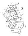
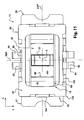
- the switch 10 illustrated in the figures exhibits a double general design symmetry relative to the vertical longitudinal mid-plane LMP and the vertical transverse mid-plane TMP indicated in Figure 11 , these planes intersecting on the vertical central axis A.
- the switch 10 essentially comprises, stacked vertically upwards along the vertical central axis A, the lower casing 12, two superposed trip members 14, two superposed flexible sealing films 16, an actuating member or actuator 18, a horizontal support plate 20 of a light-emitting diode or LED 22, and an upper cage 24 for closing off and fastening the components.
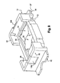
- the lower casing 12 is a hollow part of rectangular parallelepipedal general shape, this part being produced by overmoulding with an insulating plastic.
- the casing 12 comprises a lower horizontal bottom plate 26 bounded by a lower face 27, from which plate 26 there extend, vertically upwards, two longitudinal vertical side walls 28 and two transverse vertical side walls 30 that are bounded vertically upwards by an upper face or horizontal edge 32.
- the opposed internal faces 29 of the longitudinal walls 28 and 31 of the transverse walls 30, define an internal central cavity 34 in which various components of the switch 10 are placed.
- the bottom plate 26 is overmoulded, in a known manner, over two conducting, cut and folded, metal parts, namely a lateral part 36 and a central part 38.
- the fixed lateral contact 36 is extended longitudinally to the outside of the casing, beyond the external face of the lefthand transverse wall 30 when considering the figures, by a longitudinal electrical connection tab 40, the horizontal lower face 41 of which is coplanar with the lower face 27 of the bottom plate 26.
- the central contact 38 is extended longitudinally to the outside of the casing 12, beyond the external face of the right-hand transverse wall 30, by a contact plate 39, the horizontal lower face 37 of which is flush and coplanar with the lower face 27 of the bottom plate 26.
- the horizontal upper face 42 of the fixed contact 36 extends into the bottom of the cavity 34, being offset vertically above the upper face 25 of the bottom plate 26 and at the same height as the horizontal upper face 44 of an overthickness 46 made by moulding with the bottom plate 26 of insulating material.
- the fixed central contact 38 comprises a central disc 48, the conducting horizontal upper face 49 of which is at a greater height than that of the face 25 of the plate 26, but it is vertically offset downwards with respect to the horizontal plane passing through the upper face 42 of the fixed contact 36 and through the insulating horizontal face 44.
- the cavity 34 has a peripheral annular bottom 50 of rectangular outline.
- the two trip members with a tactile effect 14 are identical superposed elements made of conducting material having the general shape of a rectangular pyramid with a central dome 52.
- the outline and the dimensions of the two members are such that they are housed practically without any clearance, as may be seen in Figures 3 and 4 , so as to bear vertically on the faces 42 and 44 and beneath the edge 50.
- a central vertical downward action along the axis A on the superposed domes 52 causes, in a known manner, the sudden change of state of the members 14 in such a way that the domes 52 suddenly come into contact with the upper face 49 of the fixed central contact 38, 48 in order to establish an electrical connection between the fixed contacts 36 and 38 and therefore between the external electrical connection tabs 40 and 39.
- the bottom housing of the lower casing 12, bounded upwards by the lower horizontal edge 50, in which housing the fixed contacts 36-42 and 38-48 and the trip members 14 are placed, is closed off in a sealed manner by two superposed sealing films 16, the periphery of which is for example adhesively bonded to the upper face of the lower horizontal edge 50.
- the longitudinal side walls 28 each have a central recess 56 which extends vertically from the plane of the edge 50 right up to the top and which is bounded by transverse vertical faces 58.
- the cavity 34 houses the actuating member or actuator 18.
- the actuator 18 is a metal part made of thick sheet metal, produced by cutting and folding, which consists essentially of a lower horizontal actuating plate 60 having, at its centre, a central actuating boss 63, the convex lower face 64 of which is centred on the axis A and bears, via the films 16, on the upper face of the superposed central domes 52.
- the lower actuating plate 60 of the actuator 18 is bent over through 180° in the manner of a hairpin, thus having two horizontal bent-over parts 62 that extend longitudinally inwards towards the axis A.
- the longitudinal dimensions of the plate 60 with its bent-over parts 62 are such that it is housed practically without any clearance in the cavity 34 bounded by the internal faces 31 of the side walls 30.
- the dimensions of the plate 60 with its bent-over parts 62 are such that the upper horizontal face 64 of the bent-over parts 62 is slightly offset upwards relative to the plane of the horizontal face or horizontal upper edge 32 of the moulded lower casing 12, this dimension being determined by the stack of the actuator 18, of the films 16 and of the actuating members 14 in the bottom of the casing 12.
- the actuator 18 has two vertical central branches 66 of transverse orientation, each of which is bent back through 90° horizontally and longitudinally towards the outside so as to be extended by an upper horizontal branch 68, the branches 68 being coplanar with and bounded by two horizontal upper faces 70.
- the horizontal branches 70 allow a translucent button (not shown) to be mounted and fixed, the design of the said button depending on the application in which the switch is used.
- the support plate 20 is a plastic moulded part, this being a plate of substantially rectangular shape bounded by a plane lower horizontal face 72 so as firstly to constitute the closure plate of the cavity 34, in order to "imprison" therein the actuator 18, by extending horizontally above the horizontal upper face 61 of the lower plate 60 of the actuator 18.
- the lower face 72 bears vertically downwards on the edge 50 with interposition of the lateral outline of the sealing films 16.
- the dimension along the longitudinal direction separating the vertical transverse lateral faces 74 of the plate 20 is such that it is housed with longitudinal clearance between the facing internal faces 67 of the vertical branches 66 of the actuator 18 in such a way that the latter can move vertically downwards.
- the stack of the components is such that, in the rest position, the trip members 14 are slightly prestressed vertically, exerting a vertically upward return force on the actuator 18, via the sealing films 16, in such a way that the upper face 61 of the actuating plate 60 bears vertically upwards against the upper face 72 of the plate 20.
- the plate 20 is a moulded plastic part that is overmoulded here around four fixed contact elements 76, these being illustrated in greater detail in Figure 17 .
- Each fixed contact element 76 is a small horizontal plate bounded by a horizontal upper contact face 77.
- each small plate 76 belongs to an element made of cut and folded sheet metal.
- the four fixed contacts 76 here are arranged in a square around the central axis A, each with a central circularly arcuate recess 78 defining a vertical cylindrically arcuate face.
- Each fixed contact 76 is extended transversely outwards by a horizontal tab 80 vertically offset downwards relative to the plane of the small plates 76.
- Each tab 80 is extended by a vertical branch 82 that lies in a longitudinal vertical plane and is itself extended by a curved lower end branch 84, with its lower convex face 86 oriented downwards so as to constitute, for each fixed contact 76, an electrical connection terminal.
- the length of the horizontal tabs 80 that project transversely outwards beyond the longitudinal lateral faces 75 of the plate 20 is such that the electrical connection terminals 82-84 extend vertically outwards from the lower casing 12 and along the external faces of the longitudinal side walls 28 of the lower casing 12.
- the upper faces 77 of the four small fixed contact plates 76 are flush with the horizontal upper face 88 of the plate 20, the latter having, in the concave wall, a cylindrical central hole 90 with which the faces 78 are also flush owing to the separation of the four fixed contacts 76 after overmoulding of the body of the plate 20.
- the plate 20 has two rectangular overthicknesses 92 that cover the rest of the upper faces 77 and define, by their opposed internal vertical transverse faces 94, a central housing intended to house the light source, which here consists of the diode or LED 22.
- the latter is here of rectangular parallelepipedal general shape and has, in its lower horizontal face (not shown), electrical contact elements that bear on and are in electrical connection with the corresponding facing portions of the upper faces 77 of the small plates 76.
- the LED 22 is fastened to the support plate 20 by, for example, soldering, brazing and/or bonding by means of a conductive adhesive.
- the support plate 20 may also be overmoulded, at least partly, over the fixed contacts 76 and over the body of the diode 22.
- the diode or LED 22 extends generally vertically above the support plate 20 between the branches 66 and 68 of the actuator 18.
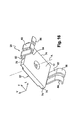
- the support plate 20 is fastened by the upper cage 24, which therefore imprisons the other components in the lower casing 12, said cage being a part made of cut and folded sheet metal having in particular an upper closure frame 100 of rectangular flat outline bounded by a lower face 102 (see Figure 15 ) which bears on the edge 32 of rectangular outline.
- the closure frame 100 is extended downwards by two transverse vertical tabs 104, each of which is housed in a complementary housing 108 formed for this purpose, by moulding, in the external face of the associated transverse side wall 30.
- the dimensions of the tabs 104 and of the housings 108 are such that the cage 24 is thus positioned practically without any clearance in the horizontal plane relative to the lower casing 12 on the upper face 32 of which it bears vertically via its frame 100-102.
- the cage 24 is extended by four longitudinal vertical tabs 106, each of which, in order to limit the transverse extent of the switch, is housed in a recess 112 provided for this purpose in the outer face of the longitudinal side wall 28, also participating in the positioning of the cage 24 relative to the casing 12.
- Each vertical fastening tab 106 is extended, at its lower end, by a crimp-fastening tab 110 that extends horizontally outwards in a substantially longitudinal direction and extends initially, that is to say before it is deformed by crimping, in the same vertical plane as the tab 106.
- each lower plate 110 is deformed transversely inwards so as to be housed in a complementary recess 112 provided for this purpose and formed at the base of the lower casing 12 in the external face of the longitudinal side wall 28, which recess also emerges in the lower face 27 of the bottom plate.
- the upper frame 100 is extended inwards beyond the edge 32 by two ribs 114 of longitudinal orientation and forming an overthickness, the vertical longitudinal faces 116 of which ribs extend opposite the vertical lateral faces 117 of the vertical branches 66 of the actuator 18.
- the upper closure frame 100 with its face 102, thus provides the positioning and the vertically upward retention of the support plate 20 of the LED 22.
- the support plate is thus sandwiched vertically between the casing 12 and the cage 24.
- each connection terminal 82-84 lies substantially in the plane of the lower face 27 of the lower casing 12, slightly offset below the latter.
- the terminals 84 are able to ensure electrical contact by elastic pressure on and/or via the soldering to the corresponding conducting tracks (not shown) of the printed-circuit board PCB.
- diodes 22 it is possible to provide one or more diodes 22 on the support plate 20, it being possible for the latter to have a larger number of electrical connection terminals depending on the number of diodes used.
Landscapes
- Push-Button Switches (AREA)
- Switch Cases, Indication, And Locking (AREA)
Claims (7)
- Elektrischer Schalter (10) mit Tasteffekt der Bauart, welche umfasst:- ein unteres Gehäuse (12), dessen Unterseite (27) so gestaltet ist, dass sie auf der Oberseite einer Platine aufliegt, welches untere Gehäuse einen inneren Hohlraum (34) bildet, in dessen Boden mindestens zwei feste elektrische Kontaktelemente (36, 38) angeordnet sind, die jeweils mit einer Anschlusszunge (40, 39) verbunden sind, die für den elektrischen Anschluss der festen Kontaktelemente an eine Leiterbahn der Platine zu Außenseite des Gehäuses (12) vorspringen;- ein Auslöseelement (14) mit allgemein kuppelförmiger Form, welches in dem Hohlraum (34) untergebracht ist und aus einem stabilen Ruhezustand unter der Einwirkung eines Betätigungselements (18) elastisch verformbar ist, dessen unterer Teil (60, 63) in dem Hohlraum (34) untergebracht ist und auf das Auslöseelement (14, 52) entlang einer zu dem Boden (26) des Hohlraums (34) annähernd senkrechten Richtung (A) wirkt;- mindestens eine Lichtquelle (22), die von einer Trägerplatte (20) getragen wird, welche sich über der offenen Oberseite des Hohlraums horizontal erstreckt, welche das Betätigungselement (18) überbrückt, welche in dem unteren Gehäuse eingeschlossen ist und welche Klemmen (82) für den elektrischen Anschluss der Lichtquelle (22) an eine Stromversorgungsschaltung für die Lichtquelle (22) einschließt, insbesondere eine solche, die von dem Schalter (10) gesteuert wird; und- einen Käfig (24) zur Befestigung der Trägerplatte (20) an dem Gehäuse (12), wobei die Trägerplatte senkrecht zwischen dem Gehäuse (12) und dem Käfig (24) sandwichartig eingeschlossen ist,
wobei die elektrischen Anschlussklemmen (82) der Lichtquelle (23) senkrecht zu Außenseite des Gehäuses (12) entlang senkrechten Seitenflächen (28) des Gehäuses verlaufen. - Schalter nach dem vorhergehenden Anspruch, dadurch gekennzeichnet, dass das Gehäuse (12) zwei senkrechte, parallele und einander gegenüberliegende Seitenwände (28) hat, deren obere Ränder jeweils ein nach oben offenes Gehäuse (56) haben, in dem ein gegenüberliegender Teil der Trägerplatte (20) untergebracht ist.
- Schalter nach dem vorhergehenden Anspruch, dadurch gekennzeichnet, dass der Befestigungskäfig ein Metallkäfig ist, der einen oberen Verschlussrahmen (100) aufweist, der den oberen Rändern (32) der Seitenwände des Gehäuses (28, 30) gegenüberliegend verläuft und senkrechte Arme (106) zur Befestigung des Rahmens (100) an dem Gehäuse (12) hat.
- Schalter nach dem vorhergehenden Anspruch, dadurch gekennzeichnet, dass der Verschlussrahmen (100) senkrecht auf den oberen Rändern (33) der Seitenwände (28, 30) des Gehäuses (12) aufliegt.
- Schalter nach einem der Ansprüche 3 und 4, dadurch gekennzeichnet, dass der obere Verschlussrahmen (100) für die Positionierung und den oberen senkrechten Rückhalt der Trägerplatte (20) sorgt.
- Schalter nach einem der vorhergehenden Ansprüche, dadurch gekennzeichnet, dass die unteren freien Enden (86) der elektrischen Anschlussklemmen (82, 84) der Lichtquelle so geformt sind, dass sie auf Leiterbahnen auf der Oberseite der Platine federnd aufliegen.
- Schalter nach einem der vorhergehenden Ansprüche, dadurch gekennzeichnet, dass die Trägerplatte (20) senkrecht nach oben die Ruheposition des Auslöseelements (18), in welche Ruheposition es elastisch rückgestellt wird, begrenzt.
Applications Claiming Priority (2)
| Application Number | Priority Date | Filing Date | Title |
|---|---|---|---|
| FR0315611A FR2864691B1 (fr) | 2003-12-31 | 2003-12-31 | Commutateur electrique lumineux a effet tactile |
| PCT/EP2004/053417 WO2005064633A1 (en) | 2003-12-31 | 2004-12-13 | Illuminated electrical switch with a tactile effect |
Publications (2)
| Publication Number | Publication Date |
|---|---|
| EP1700323A1 EP1700323A1 (de) | 2006-09-13 |
| EP1700323B1 true EP1700323B1 (de) | 2015-08-19 |
Family
ID=34639721
Family Applications (1)
| Application Number | Title | Priority Date | Filing Date |
|---|---|---|---|
| EP04820853.2A Expired - Lifetime EP1700323B1 (de) | 2003-12-31 | 2004-12-13 | Beleuchteter elektrischer schalter mit berührungseffekt |
Country Status (5)
| Country | Link |
|---|---|
| US (1) | US7427724B2 (de) |
| EP (1) | EP1700323B1 (de) |
| CN (1) | CN100583334C (de) |
| FR (1) | FR2864691B1 (de) |
| WO (1) | WO2005064633A1 (de) |
Families Citing this family (4)
| Publication number | Priority date | Publication date | Assignee | Title |
|---|---|---|---|---|
| JP4788576B2 (ja) * | 2006-11-09 | 2011-10-05 | パナソニック株式会社 | 可動接点 |
| US7825345B1 (en) | 2008-08-26 | 2010-11-02 | Kano Yoshio W | Reversely mounted tactile switch assembly and printed circuit board therewith |
| US8209868B2 (en) | 2009-07-27 | 2012-07-03 | The Gillette Company | Device with an illuminated button assembly |
| FR3068109B1 (fr) * | 2017-06-27 | 2019-10-04 | Valeo Vision | Dispositif et systeme d'eclairage pour vehicule automobile utilisant une diode electroluminescente organique |
Family Cites Families (8)
| Publication number | Priority date | Publication date | Assignee | Title |
|---|---|---|---|---|
| FR2503446B1 (fr) * | 1981-04-02 | 1984-05-25 | Secme | Commutateur miniature notamment pour circuit imprime |
| JPH0541132A (ja) * | 1991-08-07 | 1993-02-19 | Matsushita Electric Ind Co Ltd | 照光式プツシユスイツチ |
| JPH0765666A (ja) | 1993-08-24 | 1995-03-10 | Oki Electric Ind Co Ltd | 照光式スイッチ |
| FR2771846B1 (fr) * | 1997-11-28 | 1999-12-31 | Itt Mfg Enterprises Inc | Commutateur electrique a effet tactile a plusieurs voies et a organe de declenchement unique |
| US6310308B1 (en) * | 2000-09-20 | 2001-10-30 | Spectra Lux Corporation | Compact push-button switch assembly |
| FR2849953B1 (fr) * | 2003-01-10 | 2005-04-08 | Itt Mfg Entpr S Inc | Dispositif de commutation a source lumineuse integree. |
| US6756554B1 (en) * | 2003-04-29 | 2004-06-29 | Hon Hai Precision Ind. Co., Ltd. | Tact switch |
| FR2859818B1 (fr) * | 2003-09-12 | 2013-07-26 | Itt Mfg Enterprises Inc | Dispositif de commutation equipe d'une source lumineuse |
-
2003
- 2003-12-31 FR FR0315611A patent/FR2864691B1/fr not_active Expired - Fee Related
-
2004
- 2004-12-13 CN CN200480037271A patent/CN100583334C/zh not_active Expired - Fee Related
- 2004-12-13 WO PCT/EP2004/053417 patent/WO2005064633A1/en not_active Ceased
- 2004-12-13 EP EP04820853.2A patent/EP1700323B1/de not_active Expired - Lifetime
-
2006
- 2006-05-25 US US11/442,495 patent/US7427724B2/en not_active Expired - Fee Related
Also Published As
| Publication number | Publication date |
|---|---|
| US7427724B2 (en) | 2008-09-23 |
| CN100583334C (zh) | 2010-01-20 |
| US20060278515A1 (en) | 2006-12-14 |
| CN1894761A (zh) | 2007-01-10 |
| FR2864691A1 (fr) | 2005-07-01 |
| FR2864691B1 (fr) | 2006-03-10 |
| EP1700323A1 (de) | 2006-09-13 |
| WO2005064633A1 (en) | 2005-07-14 |
Similar Documents
| Publication | Publication Date | Title |
|---|---|---|
| EP1218903B1 (de) | Verbesserter elektroschalter mit fühlbarem effekt und einen einzigen schaltglied | |
| US7906739B2 (en) | Arrangement for surface mounting an electrical component by soldering, and electrical component for such an arrangement | |
| US7655859B2 (en) | Connector for a solar module | |
| US6100484A (en) | Electrical switch with insert-molded circuitry | |
| US8902603B2 (en) | Solder and lead free electronic circuit and method of manufacturing same | |
| US20030213686A1 (en) | Push switch | |
| US7202429B2 (en) | Switch with light supported in operating member | |
| US7427724B2 (en) | Illuminated electrical switch with a tactile effect | |
| US4364619A (en) | Interconnection system for printed circuit board devices | |
| KR0149161B1 (ko) | 키보드 스위치의 제조방법 및 키보드 스위치 | |
| US4368369A (en) | Electrical switch | |
| JP3541797B2 (ja) | 電気スイッチ | |
| HK1007629B (en) | Method of producing a keyboard switch and keyboard switch obtained | |
| JPH11232962A (ja) | プッシュオンスイッチ | |
| KR200284437Y1 (ko) | 피씨비형 택트 스위치 | |
| US6495780B1 (en) | Waterproof sealed switch with a single contact and method for manufacturing same | |
| EP0841673A2 (de) | Elektrischer Schaltmodul | |
| US4753000A (en) | Method of making snap action switches | |
| KR960038270A (ko) | 공기조화기 | |
| KR100458968B1 (ko) | 플랙시블 피씨비형 택트 스위치 | |
| EP0155390B1 (de) | Herstellungsverfahren eines Schnappschalters | |
| KR20070112143A (ko) | 상보형 다이오드부를 갖는 스위치 | |
| JPH0531042U (ja) | 押釦スイツチのキートツプ | |
| KR200297764Y1 (ko) | 택트 스위치 | |
| JP2002033029A (ja) | キートップの取付構造 |
Legal Events
| Date | Code | Title | Description |
|---|---|---|---|
| PUAI | Public reference made under article 153(3) epc to a published international application that has entered the european phase |
Free format text: ORIGINAL CODE: 0009012 |
|
| 17P | Request for examination filed |
Effective date: 20060522 |
|
| AK | Designated contracting states |
Kind code of ref document: A1 Designated state(s): AT BE BG CH CY CZ DE DK EE ES FI FR GB GR HU IE IS IT LI LT LU MC NL PL PT RO SE SI SK TR |
|
| DAX | Request for extension of the european patent (deleted) | ||
| 17Q | First examination report despatched |
Effective date: 20070726 |
|
| RAP1 | Party data changed (applicant data changed or rights of an application transferred) |
Owner name: COACTIVE TECHNOLOGIES, INC. |
|
| RAP1 | Party data changed (applicant data changed or rights of an application transferred) |
Owner name: COACTIVE TECHNOLOGIES, LLC |
|
| RAP1 | Party data changed (applicant data changed or rights of an application transferred) |
Owner name: COACTIVE TECHNOLOGIES, LLC |
|
| GRAP | Despatch of communication of intention to grant a patent |
Free format text: ORIGINAL CODE: EPIDOSNIGR1 |
|
| RIC1 | Information provided on ipc code assigned before grant |
Ipc: H01H 13/02 20060101AFI20150326BHEP Ipc: H01H 9/18 20060101ALI20150326BHEP |
|
| INTG | Intention to grant announced |
Effective date: 20150428 |
|
| GRAS | Grant fee paid |
Free format text: ORIGINAL CODE: EPIDOSNIGR3 |
|
| GRAA | (expected) grant |
Free format text: ORIGINAL CODE: 0009210 |
|
| AK | Designated contracting states |
Kind code of ref document: B1 Designated state(s): AT BE BG CH CY CZ DE DK EE ES FI FR GB GR HU IE IS IT LI LT LU MC NL PL PT RO SE SI SK TR |
|
| REG | Reference to a national code |
Ref country code: GB Ref legal event code: FG4D |
|
| REG | Reference to a national code |
Ref country code: CH Ref legal event code: EP |
|
| REG | Reference to a national code |
Ref country code: IE Ref legal event code: FG4D |
|
| REG | Reference to a national code |
Ref country code: AT Ref legal event code: REF Ref document number: 744317 Country of ref document: AT Kind code of ref document: T Effective date: 20150915 |
|
| REG | Reference to a national code |
Ref country code: DE Ref legal event code: R096 Ref document number: 602004047738 Country of ref document: DE |
|
| REG | Reference to a national code |
Ref country code: FR Ref legal event code: PLFP Year of fee payment: 12 |
|
| REG | Reference to a national code |
Ref country code: AT Ref legal event code: MK05 Ref document number: 744317 Country of ref document: AT Kind code of ref document: T Effective date: 20150819 |
|
| REG | Reference to a national code |
Ref country code: LT Ref legal event code: MG4D |
|
| REG | Reference to a national code |
Ref country code: NL Ref legal event code: MP Effective date: 20150819 |
|
| PG25 | Lapsed in a contracting state [announced via postgrant information from national office to epo] |
Ref country code: GR Free format text: LAPSE BECAUSE OF FAILURE TO SUBMIT A TRANSLATION OF THE DESCRIPTION OR TO PAY THE FEE WITHIN THE PRESCRIBED TIME-LIMIT Effective date: 20151120 Ref country code: FI Free format text: LAPSE BECAUSE OF FAILURE TO SUBMIT A TRANSLATION OF THE DESCRIPTION OR TO PAY THE FEE WITHIN THE PRESCRIBED TIME-LIMIT Effective date: 20150819 Ref country code: LT Free format text: LAPSE BECAUSE OF FAILURE TO SUBMIT A TRANSLATION OF THE DESCRIPTION OR TO PAY THE FEE WITHIN THE PRESCRIBED TIME-LIMIT Effective date: 20150819 |
|
| PG25 | Lapsed in a contracting state [announced via postgrant information from national office to epo] |
Ref country code: PL Free format text: LAPSE BECAUSE OF FAILURE TO SUBMIT A TRANSLATION OF THE DESCRIPTION OR TO PAY THE FEE WITHIN THE PRESCRIBED TIME-LIMIT Effective date: 20150819 Ref country code: AT Free format text: LAPSE BECAUSE OF FAILURE TO SUBMIT A TRANSLATION OF THE DESCRIPTION OR TO PAY THE FEE WITHIN THE PRESCRIBED TIME-LIMIT Effective date: 20150819 Ref country code: SE Free format text: LAPSE BECAUSE OF FAILURE TO SUBMIT A TRANSLATION OF THE DESCRIPTION OR TO PAY THE FEE WITHIN THE PRESCRIBED TIME-LIMIT Effective date: 20150819 Ref country code: ES Free format text: LAPSE BECAUSE OF FAILURE TO SUBMIT A TRANSLATION OF THE DESCRIPTION OR TO PAY THE FEE WITHIN THE PRESCRIBED TIME-LIMIT Effective date: 20150819 Ref country code: IS Free format text: LAPSE BECAUSE OF FAILURE TO SUBMIT A TRANSLATION OF THE DESCRIPTION OR TO PAY THE FEE WITHIN THE PRESCRIBED TIME-LIMIT Effective date: 20151219 Ref country code: PT Free format text: LAPSE BECAUSE OF FAILURE TO SUBMIT A TRANSLATION OF THE DESCRIPTION OR TO PAY THE FEE WITHIN THE PRESCRIBED TIME-LIMIT Effective date: 20151221 |
|
| PG25 | Lapsed in a contracting state [announced via postgrant information from national office to epo] |
Ref country code: NL Free format text: LAPSE BECAUSE OF FAILURE TO SUBMIT A TRANSLATION OF THE DESCRIPTION OR TO PAY THE FEE WITHIN THE PRESCRIBED TIME-LIMIT Effective date: 20150819 |
|
| PG25 | Lapsed in a contracting state [announced via postgrant information from national office to epo] |
Ref country code: SK Free format text: LAPSE BECAUSE OF FAILURE TO SUBMIT A TRANSLATION OF THE DESCRIPTION OR TO PAY THE FEE WITHIN THE PRESCRIBED TIME-LIMIT Effective date: 20150819 Ref country code: EE Free format text: LAPSE BECAUSE OF FAILURE TO SUBMIT A TRANSLATION OF THE DESCRIPTION OR TO PAY THE FEE WITHIN THE PRESCRIBED TIME-LIMIT Effective date: 20150819 Ref country code: CZ Free format text: LAPSE BECAUSE OF FAILURE TO SUBMIT A TRANSLATION OF THE DESCRIPTION OR TO PAY THE FEE WITHIN THE PRESCRIBED TIME-LIMIT Effective date: 20150819 Ref country code: IT Free format text: LAPSE BECAUSE OF FAILURE TO SUBMIT A TRANSLATION OF THE DESCRIPTION OR TO PAY THE FEE WITHIN THE PRESCRIBED TIME-LIMIT Effective date: 20150819 Ref country code: DK Free format text: LAPSE BECAUSE OF FAILURE TO SUBMIT A TRANSLATION OF THE DESCRIPTION OR TO PAY THE FEE WITHIN THE PRESCRIBED TIME-LIMIT Effective date: 20150819 |
|
| REG | Reference to a national code |
Ref country code: DE Ref legal event code: R097 Ref document number: 602004047738 Country of ref document: DE |
|
| PG25 | Lapsed in a contracting state [announced via postgrant information from national office to epo] |
Ref country code: BE Free format text: LAPSE BECAUSE OF NON-PAYMENT OF DUE FEES Effective date: 20151231 Ref country code: RO Free format text: LAPSE BECAUSE OF FAILURE TO SUBMIT A TRANSLATION OF THE DESCRIPTION OR TO PAY THE FEE WITHIN THE PRESCRIBED TIME-LIMIT Effective date: 20150819 |
|
| PLBE | No opposition filed within time limit |
Free format text: ORIGINAL CODE: 0009261 |
|
| STAA | Information on the status of an ep patent application or granted ep patent |
Free format text: STATUS: NO OPPOSITION FILED WITHIN TIME LIMIT |
|
| 26N | No opposition filed |
Effective date: 20160520 |
|
| PG25 | Lapsed in a contracting state [announced via postgrant information from national office to epo] |
Ref country code: LU Free format text: LAPSE BECAUSE OF FAILURE TO SUBMIT A TRANSLATION OF THE DESCRIPTION OR TO PAY THE FEE WITHIN THE PRESCRIBED TIME-LIMIT Effective date: 20151213 Ref country code: MC Free format text: LAPSE BECAUSE OF FAILURE TO SUBMIT A TRANSLATION OF THE DESCRIPTION OR TO PAY THE FEE WITHIN THE PRESCRIBED TIME-LIMIT Effective date: 20150819 |
|
| REG | Reference to a national code |
Ref country code: CH Ref legal event code: PL |
|
| GBPC | Gb: european patent ceased through non-payment of renewal fee |
Effective date: 20151213 |
|
| PG25 | Lapsed in a contracting state [announced via postgrant information from national office to epo] |
Ref country code: SI Free format text: LAPSE BECAUSE OF FAILURE TO SUBMIT A TRANSLATION OF THE DESCRIPTION OR TO PAY THE FEE WITHIN THE PRESCRIBED TIME-LIMIT Effective date: 20150819 |
|
| REG | Reference to a national code |
Ref country code: IE Ref legal event code: MM4A |
|
| PG25 | Lapsed in a contracting state [announced via postgrant information from national office to epo] |
Ref country code: IE Free format text: LAPSE BECAUSE OF NON-PAYMENT OF DUE FEES Effective date: 20151213 Ref country code: GB Free format text: LAPSE BECAUSE OF NON-PAYMENT OF DUE FEES Effective date: 20151213 Ref country code: LI Free format text: LAPSE BECAUSE OF NON-PAYMENT OF DUE FEES Effective date: 20151231 Ref country code: CH Free format text: LAPSE BECAUSE OF NON-PAYMENT OF DUE FEES Effective date: 20151231 |
|
| REG | Reference to a national code |
Ref country code: FR Ref legal event code: PLFP Year of fee payment: 13 |
|
| PG25 | Lapsed in a contracting state [announced via postgrant information from national office to epo] |
Ref country code: BE Free format text: LAPSE BECAUSE OF FAILURE TO SUBMIT A TRANSLATION OF THE DESCRIPTION OR TO PAY THE FEE WITHIN THE PRESCRIBED TIME-LIMIT Effective date: 20150819 |
|
| PGFP | Annual fee paid to national office [announced via postgrant information from national office to epo] |
Ref country code: FR Payment date: 20161227 Year of fee payment: 13 |
|
| PGFP | Annual fee paid to national office [announced via postgrant information from national office to epo] |
Ref country code: DE Payment date: 20161229 Year of fee payment: 13 |
|
| PG25 | Lapsed in a contracting state [announced via postgrant information from national office to epo] |
Ref country code: HU Free format text: LAPSE BECAUSE OF FAILURE TO SUBMIT A TRANSLATION OF THE DESCRIPTION OR TO PAY THE FEE WITHIN THE PRESCRIBED TIME-LIMIT; INVALID AB INITIO Effective date: 20041213 Ref country code: BG Free format text: LAPSE BECAUSE OF FAILURE TO SUBMIT A TRANSLATION OF THE DESCRIPTION OR TO PAY THE FEE WITHIN THE PRESCRIBED TIME-LIMIT Effective date: 20150819 |
|
| PG25 | Lapsed in a contracting state [announced via postgrant information from national office to epo] |
Ref country code: CY Free format text: LAPSE BECAUSE OF FAILURE TO SUBMIT A TRANSLATION OF THE DESCRIPTION OR TO PAY THE FEE WITHIN THE PRESCRIBED TIME-LIMIT Effective date: 20150819 |
|
| PG25 | Lapsed in a contracting state [announced via postgrant information from national office to epo] |
Ref country code: TR Free format text: LAPSE BECAUSE OF FAILURE TO SUBMIT A TRANSLATION OF THE DESCRIPTION OR TO PAY THE FEE WITHIN THE PRESCRIBED TIME-LIMIT Effective date: 20150819 |
|
| REG | Reference to a national code |
Ref country code: DE Ref legal event code: R119 Ref document number: 602004047738 Country of ref document: DE |
|
| REG | Reference to a national code |
Ref country code: FR Ref legal event code: ST Effective date: 20180831 |
|
| PG25 | Lapsed in a contracting state [announced via postgrant information from national office to epo] |
Ref country code: DE Free format text: LAPSE BECAUSE OF NON-PAYMENT OF DUE FEES Effective date: 20180703 Ref country code: FR Free format text: LAPSE BECAUSE OF NON-PAYMENT OF DUE FEES Effective date: 20180102 |