EP1219060B1 - Procede et dispositif de transmission de trames de donnees et procede et dispositif d'adaptation des debits de donnees - Google Patents
Procede et dispositif de transmission de trames de donnees et procede et dispositif d'adaptation des debits de donnees Download PDFInfo
- Publication number
- EP1219060B1 EP1219060B1 EP00969267.4A EP00969267A EP1219060B1 EP 1219060 B1 EP1219060 B1 EP 1219060B1 EP 00969267 A EP00969267 A EP 00969267A EP 1219060 B1 EP1219060 B1 EP 1219060B1
- Authority
- EP
- European Patent Office
- Prior art keywords
- repetition
- repeated
- bit
- bits
- frames
- Prior art date
- Legal status (The legal status is an assumption and is not a legal conclusion. Google has not performed a legal analysis and makes no representation as to the accuracy of the status listed.)
- Expired - Lifetime
Links
- 238000000034 method Methods 0.000 title claims description 62
- 238000006073 displacement reaction Methods 0.000 claims description 14
- 238000004364 calculation method Methods 0.000 claims description 12
- 230000032258 transport Effects 0.000 description 19
- 238000004891 communication Methods 0.000 description 17
- 230000000694 effects Effects 0.000 description 11
- 230000005540 biological transmission Effects 0.000 description 9
- 230000008569 process Effects 0.000 description 6
- 230000006978 adaptation Effects 0.000 description 3
- 230000008901 benefit Effects 0.000 description 3
- 238000006243 chemical reaction Methods 0.000 description 3
- 238000009826 distribution Methods 0.000 description 3
- 238000012986 modification Methods 0.000 description 3
- 230000004048 modification Effects 0.000 description 3
- 238000010586 diagram Methods 0.000 description 2
- 239000011159 matrix material Substances 0.000 description 2
- 238000010295 mobile communication Methods 0.000 description 2
- 238000006467 substitution reaction Methods 0.000 description 2
- 238000009827 uniform distribution Methods 0.000 description 2
- ZIIRLFNUZROIBX-UHFFFAOYSA-N 2,3,5-trichlorobenzene-1,4-diol Chemical compound OC1=CC(Cl)=C(O)C(Cl)=C1Cl ZIIRLFNUZROIBX-UHFFFAOYSA-N 0.000 description 1
- 238000013459 approach Methods 0.000 description 1
- 230000015556 catabolic process Effects 0.000 description 1
- 230000001010 compromised effect Effects 0.000 description 1
- 239000004020 conductor Substances 0.000 description 1
- 238000012937 correction Methods 0.000 description 1
- 238000013523 data management Methods 0.000 description 1
- 230000007423 decrease Effects 0.000 description 1
- 230000003247 decreasing effect Effects 0.000 description 1
- 238000006731 degradation reaction Methods 0.000 description 1
- 230000001419 dependent effect Effects 0.000 description 1
- 230000006866 deterioration Effects 0.000 description 1
- 230000001627 detrimental effect Effects 0.000 description 1
- 238000011161 development Methods 0.000 description 1
- 230000018109 developmental process Effects 0.000 description 1
- 238000005516 engineering process Methods 0.000 description 1
- 230000007717 exclusion Effects 0.000 description 1
- 239000000835 fiber Substances 0.000 description 1
- 238000009472 formulation Methods 0.000 description 1
- 230000006872 improvement Effects 0.000 description 1
- 230000000116 mitigating effect Effects 0.000 description 1
- 239000000203 mixture Substances 0.000 description 1
- 238000005457 optimization Methods 0.000 description 1
- 238000012545 processing Methods 0.000 description 1
- 230000003252 repetitive effect Effects 0.000 description 1
- 238000012546 transfer Methods 0.000 description 1
Images


Classifications
-
- H—ELECTRICITY
- H04—ELECTRIC COMMUNICATION TECHNIQUE
- H04B—TRANSMISSION
- H04B14/00—Transmission systems not characterised by the medium used for transmission
- H04B14/02—Transmission systems not characterised by the medium used for transmission characterised by the use of pulse modulation
- H04B14/04—Transmission systems not characterised by the medium used for transmission characterised by the use of pulse modulation using pulse code modulation
-
- H—ELECTRICITY
- H04—ELECTRIC COMMUNICATION TECHNIQUE
- H04L—TRANSMISSION OF DIGITAL INFORMATION, e.g. TELEGRAPHIC COMMUNICATION
- H04L1/00—Arrangements for detecting or preventing errors in the information received
- H04L1/004—Arrangements for detecting or preventing errors in the information received by using forward error control
- H04L1/0056—Systems characterized by the type of code used
- H04L1/0067—Rate matching
- H04L1/0068—Rate matching by puncturing
- H04L1/0069—Puncturing patterns
-
- H—ELECTRICITY
- H04—ELECTRIC COMMUNICATION TECHNIQUE
- H04L—TRANSMISSION OF DIGITAL INFORMATION, e.g. TELEGRAPHIC COMMUNICATION
- H04L1/00—Arrangements for detecting or preventing errors in the information received
- H04L1/08—Arrangements for detecting or preventing errors in the information received by repeating transmission, e.g. Verdan system
Definitions
- the present invention relates to a method and a device for transmitting data frames and to a method and a device for data rate adaptation, in particular using a repetition of bits to be transmitted.
- Digital communication systems are designed to communicate data by presenting the data in a form that facilitates transmission of the data over a communication medium.
- the data is transmitted as radio signals between transmitters and receivers of the communication system.
- the data may be displayed as light and transmitted, for example, over a fiber optic network between transmitters and receivers of the system.
- the data communication systems often include means for mitigating the corruption of data that occurs during transmission.
- One of these means is to provide transmitters of the system with encoders that encode the data before transmission in accordance with an error control code.
- the error control code is designed to add redundancy to the data in a controlled manner.
- the decoding is effected using an error decoding algorithm corresponding to the error control code known to the receiver.
- rate matching often requires puncturing or repeating data bits or symbols from a block of encoded data before transmitting that data.
- the term puncturing / repetition is intended here to mean a process of removing or deleting bits from a coded data block, with the effect that the punctured bits are not transmitted with this data block or signify a process of repeating bits from a coded data block the effect that the bits to be repeated are transmitted several times with this data block.
- puncturing might be required because a multiple access method used to communicate the data across the data-carrying media requires formatting the data into blocks of a predetermined size that does not match the size of the coded data frame.
- data bits from the encoded data frame are either dotted, in order to reduce the size of the coded data block in a case where the coded data frame is larger than the size of the transport block or repeats bits of the coded data frame in a case where the coded data frame is smaller than the predetermined size of the transport block ,
- the data bits (bits) or symbols are repeated (repeating) in an amount necessary for filling the rest of the transport data block.
- bit positions should also be used in a coded or uncoded data frame where data bits are to be repeated, arranged they are evenly separated throughout the data frame.
- EP 0912009 discloses a data rate adjuster wherein only one always rigidly performing the same repetition is performed for each frame.
- Known methods for selecting the positions of bits or symbols to be punctured or repeated in a coded data frame include dividing the number of bits or symbols in a frame by the number of bits or symbols to be punctured or repeated, and selecting bit positions having integer values corresponding to the division.
- the number of bits to be punctured is not an integer division of the number of bits of the data frame, a uniform spacing of the punctured or repeated bit positions does not occur, thereby causing the disadvantage that certain bit positions become closer as this whole number lie to each other or further than this whole number are apart from each other (partly clearly further) and in some cases also beside each other.
- interleaving is performed in a two-step transport multiplexing process.
- the various solutions to puncturing / repetition have certain consequences when puncturing is performed after the first interleaver, as intended for the UMTS system.
- the bits associated with a frame are still nested by a second interleaver, for example described in TS 25.212 (see below for more details), chapter "4.2.11 2nd interleaving".
- this second interleaver has no influence on aspects of puncturing / repetition and will therefore not be considered further in the following; in terms of the present invention, it is meaningless. Therefore, the above-mentioned first interleaver in this document is often called simply interleaver.
- a block interleaver with a column swap works as follows: First, the bits are written into a matrix line by line. This matrix consists of F columns, where F is the number of frames (also called radio frames or columns hereafter) to which the data of a data frame is distributed; See also TS 25.212 (for more details see below) chapter "4.2.5 1st interleaving".
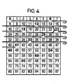
- FIG. 4 an interleaving interval of 80ms and a repetition rate of 1: 6 are assumed.
- the bold numbers indicate the bits to be repeated. Repeating every 6th bit would repeat only bits in the columns 0,2,4,6 but not in the columns 1,3,5,7, resulting in an uneven distribution of the repeated bits on the radio frames.
- the recurrence interval is sometimes changed (once in this example) to prevent the same columns from being always punctured. This will be in Fig. 4 shown.
- the narrow horizontal arrows in thin contours show a repetition distance of 6 and the broad horizontal arrow in thick outline a different repetition distance of 5, to avoid that the first column is repeated a second time too early.
- the repeat pattern can be shifted down 6 lines to determine the next bits to repeat (starting at 48) and so on. Obviously, this approach is equivalent to puncturing a column every 6th bit and shifting that puncturing pattern in different columns relative to each other.
- N c be the number of bits per radio frame before rate matching
- N i be the number of bits per radio frame after the rate match
- the frame number with k and the number of frames over which the interleaving is performed is denoted by F.
- N c > N i ie puncturing
- the formulas are also applicable to the case of repetition.
- the displacement of the puncturing pattern can then be determined by the following formulas.
- the context of the entire application takes place after the double-line "-" a comment of the corresponding steps.
- e offset is sometimes called e init .
- the rate matching method for UMTS applied within a single frame is described in TS25.212 (for more details see above), section 4.2.7.4 "Rate matching pattern determination”. It describes an error control based puncturing procedure. This process is described again here:
- the bits are denoted as follows: x i, 1 , x i, 2 , x i, 3 , x i, 4 ,... X i, N , where i is the number of the transport channel (TrCH number) and N is the parameter defined in chapter 4.2.7.2 of TS 25.212.
- the rate matching algorithm then works as follows:
- E e offset (k) then initializes e in advance in the rate matching process.
- this known method produces the same perfect puncturing pattern that would be applied by puncturing using the rate matching method just before interleaving.
- adjacent bits are never punctured; however, a distance between punctured bits may be larger than the others by up to lcd (q, F) +1.
- This method can also be applied to bit repeats (bit repetitions). Although repeating adjacent bits does not affect the performance of the error correction codes as much as does puncturing adjacent bits, it is still advantageous to distribute repeated bits as evenly as possible.
- the basic objective of this known method is to achieve a uniform spacing between the punctured bits in the original order, but taking into account the constraint that the same number of Is to puncture bits. This is achieved by decreasing the puncturing distance by 1 in certain cases.
- the presented method is optimal in that it never decreases the distance by more than 1 and reduces it only as often as necessary. This gives the best possible puncturing pattern under the limitations mentioned above.
- the optimized method obviously not only avoids puncturing of adjacent bits, but also distributes punctured bits equally spaced in the original sequence. In fact, the same properties are achieved as if puncturing had been done immediately after encoding before interleaving.
- next case ie puncturing with 1: 8 ( FIG. 7 ). Again, puncturing of adjacent bits is avoided. In this case it is not possible to achieve evenly spaced puncturing because then all the bits of a single frame would be punctured, which is totally unacceptable. In this case, most of the distances between adjacent bits are 7 (only 1 less than optimal distribution). But some distances are bigger (every eighth).
- the invention has the object, these disadvantages of the prior Reduce technology.
- the invention is therefore based on the recognition that the decoding result in the receiver depends on the repetition patterns in the transmitter, and the criteria for a good puncturing pattern and a good repetition pattern are different from each other.
- the criteria that are relevant for a good repetition pattern in determining the repeat pattern in the case of repetition, an improvement in performance compared to the patterns presented in R1-99641 can be achieved.
- Mobile radio communication systems are provided with multiple access systems operating according to, for example, Time Division Multiple Access (TDMA), such as the one used in the Global Mobile Radio System (GSM), a standard for the European Telecommunications Standards Institute mobile communication standard.
- TDMA Time Division Multiple Access
- GSM Global Mobile Radio System
- CDMA code division multiple access
- any data communication system could be used to illustrate an exemplary embodiment of the present invention, such as a local area network or a broadband telecommunications network operating according to the asynchronous transfer mode.
- exemplary data communication systems are particularly characterized in that data is transmitted as frames, packets or blocks.
- the data is stored in frames of data-carrying Transports radio signals that represent a predetermined data size.
- An example of such a mobile radio communication system is in FIG. 2 shown.
- FIG. 2 For example, three base stations BS are shown which exchange radio signals with mobile stations MS in a radio coverage area formed by cells 1 defined by dashed lines 2.
- the base stations BS are coupled together with a network relay system NET.
- the mobile stations MS and the base stations BS exchange data by transmitting radio signals marked 4 between antennas 6 coupled to the mobile stations MS and to the base stations BS.
- the data is transmitted between the mobile stations MS and the base stations BS using a data communication device in which the data is transformed into the radio signals 4 transmitted to the reception antenna 6 which detects the radio signals.
- the data is recovered by the receiver from the radio signals.
- FIG. 3 shows an example of a data communication device that forms a radio communication link between one of the mobile stations MS and one of the base stations BS, elements which are also shown in FIG FIG. 2 appear, carry identical numerical designations.
- a data source 10 generates data frames 8 at a rate determined by a type of data that the source generates.
- the data frames 8 generated by the source 10 are supplied to a rate converter 12, which acts to convert the data frames 8 to transport data blocks 14.
- the transport data blocks 14 are designed to be substantially equal in size with a predetermined one Size and amount of data that can be carried by frames of data-carrying radio signals over which data is transmitted through a radio interface formed by a pair of transmitter 18 and receiver 22.
- the data transport block 14 is supplied to a radio access processor 16, which acts to sequentially control the transmission of the transport data block 14 via the radio access interface.
- the transport data block 14 is supplied by the radio access processor 16 to a transmitter 18 which acts to translate the transport data block into the frame of data carrying radio signals transmitted in a time allocated for the transmitter to transmit the radio signals cause.
- an antenna 6 "of the receiver detects the radio signals and downconverts and restores the data frame which is fed to a radio access sequencer 24.
- the radio access scheduling inversion device 24 supplies the received data transport block to rate conversion inverting device 26 under the control of the multiple access scheduling inversion device 24, which is effected via a conductor 28.
- the rate conversion reverser 26 then supplies a representation of the restored data frame 8 to a target or data frame 8 sink represented by the block 30.
- the rate converter 12 and the rate conversion reverser 26 are designed to optimally, as far as possible, those available in the transport data block 14 Take advantage of data management capacity. This is accomplished in accordance with the exemplary embodiment of the present invention by the rate matching converter 12, which acts to encode the data frame and then puncture or repeat data bits or symbols selected from the encoded data frame with the effect of generating a transport data block. which fits into the data blocks 14.
- the rate converter 12 has an encoder and a puncturer.
- the data frame 8 supplied to the encoder is encoded to produce a coded data frame which is fed to the puncturer.
- the coded data frame is then punctured by the puncturer to produce the data transport block 14.
- Dotting or repetition is achieved by applying a common puncturing pattern or repeating pattern in the different frames shifted relative to each other. although puncturing / repetition is applied after the (inter-radio frame) interleaver, the same effect i. achieves the same punctuation / repetition pattern as if the punctuation / repetition were applied before the column interchange.
- the method described above can still be improved in the event of repetition. This is possible because there are some differences between good repeating and puncturing patterns: puncturing is particularly detrimental to puncturing consecutive bits. Furthermore, it should be avoided that the distance between successive punctured bits is significantly smaller than the average puncturing distance. The reason for this is that puncturing is more intense or shorter The bit error rate increases disproportionately locally, which then affects the overall performance.
- e offset k 2 * S k * / N i - N c / + 1 mod 2 ⁇ NC
- the puncturing / repeating patterns of the individual columns k are shifted relative to each other by the amount S (k). If a so-called error distribution algorithm is used for the calculation of the bits to be punctured / repeated, this shift can be achieved by preloading the initial error value, as shown above. Of course, other implementations are possible to achieve the displacement, especially when using another puncturing method within a column.
- Puncation rate itself theoretically can not exceed 100% in any case (that is, every bit is punctured). In practice, at puncturing rates greater than about 20% (perhaps 50% in special cases), the decoding performance will be so severely compromised that one will avoid such high puncturing rates. However, there are no such restrictions on the repetition rate. A repetition rate of 100% (ie each bit is transmitted twice) is quite possible, even higher repetition rates are possible. Each bit can be repeated several times. The more repetitions that are sent, the higher the probability of correct decoding.
- a repetition rate of 80% (ie, 80% of the bits are transmitted twice and 20% are transmitted only once (not repeated)) can also be interpreted so that each bit is repeated (that is, transmitted twice) but 20% of the bits (more precisely 20% of the original bits before doubling).
- 20% of the bits are transmitted with less energy compared to the rest and thus lower reliability. This is very similar to the case where 20% of the bits are punctured.
- a puncture pattern that is optimal for 20% puncturing will also be optimal for a repetition of 80% when the following substitution is made: 20% punctuation 80% repetition dotted bit not repeated bit not punctured bit repeated bit
- a puncturing method as described above and also provided for UMTS in TS25.212 is performed in the case where puncturing occurs before the first interleaver will also generate equivalent patterns in the two cases mentioned above; if necessary, the patterns will be shifted by a constant amount relative to each other.
- the puncturing is performed only after the first interleaver (inter-frame interleaver)
- this requires a modification of the method. This modification is described for the case of puncturing in the aforementioned article R1-99641 (optimized shifting of the puncturing patterns) and in the case of the repetition described above (optimized shifting of the patterns for repetition).
- N c the number of bits before the rate match
- N i the number of bits after the rate match.
- a puncturing rate of 20% is equivalent to a repetition rate of 80%, 180%, 280%, and so on, for the optimal displacement of the patterns between the columns.
- a repetition rate of 30% is equivalent to a repetition rate of 130%, 230%, 330% and so on.
- Another aspect of this embodiment is now the recognition that the relative displacement of the puncturing patterns in the individual columns can also be calculated based on this effective repetition rate re instead of the actual repetition rate. Depending on whether re is greater or less than 0, the formula for calculating the shift for puncturing or the formula for calculating the shift for repetition will be used.
- N c / 2 There are several ways to calculate N c / 2 if N c is odd. You can round up, round off or continue to count with fractional values, so renounce the rounding.
- the sign of q carries the information according to this calculation method, whether a repetition or puncturing is performed. Before q is used in the corresponding formula, it may be necessary to calculate the absolute value first.
- an equivalent puncturing / repetition rate re is calculated by modulo operations.
- modulo operations can only use modulo operations to account for multiples of 100% in the rate, and implement the discrimination of whether the rate is greater or less than 50% by a query.
- q can still calculate q as a signed quantity in order to preserve the advantage of the previous embodiment, ie the uniform calculation of puncturing and repetition. To avoid divisions by 0, it may be necessary in the event that no adjustment must be carried out separately. This leads to the following equivalent formulas:
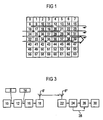
- Fig. 1 shows the resulting pattern for the proposed repeat pattern for a repetition rate of 1: 4.
- Bold numbers or numbers at which arrows begin or end indicate repeating bits.
- the arrows with thin outlines (eg the arrow from 8 to 12) denote a distance between adjacent repeated bits of 4, thin arrows (eg the arrow from 12 to 17) the distance 5 and the arrow in thick outline (eg the arrow of 39 to 40) the distance 1.
- Fig. 8 the same case for the previously used repetition method, as it was presented eg in R1-99641.
- the arrows with thin contours denote a distance between adjacent repeated bits of 4, thin arrows (eg the arrow from 12 to 15) the distance 3 and the arrow in thick outline (eg the arrow of 33 to 40) the distance 7.
- the repetition pattern within the scope of the invention has a larger spacing between repeated bits (7 in Fig. 8 ) avoids. Since in particular the large distances between repetitions cause a deterioration of the performance, and since the inventive method avoids such large distances, the application of the method according to the invention is advantageous.
- the repetition method of the present invention it is possible to generate practically optimal repetition patterns when the rate matching is applied after the first interleaver.
- the method is not particularly expensive, especially since it has to be applied only once per radio frame, not for every bit.
Landscapes
- Engineering & Computer Science (AREA)
- Computer Networks & Wireless Communication (AREA)
- Signal Processing (AREA)
- Detection And Prevention Of Errors In Transmission (AREA)
- Error Detection And Correction (AREA)
- Transmission Systems Not Characterized By The Medium Used For Transmission (AREA)
- Mobile Radio Communication Systems (AREA)
Claims (6)
- Procédé d'adaptation de débits de données dans un système UMTS (système de télécommunication mobile universel),- dans lequel les données à transmettre sont distribuées sous la forme de bits sur une série de trames par un premier dispositif d'entrelacement ;- dans lequel, pour l'adaptation du débit des données après l'entrelacement, un procédé de répétition est exécuté de sorte que le même nombre de bits soit répété dans chaque trame ;- dans lequel le motif répétitif appliqué à l'intérieur d'une trame est aussi appliqué, décalé, à l'intérieur d'autres trames de la série de trames, et- dans lequel les bits à répéter peuvent être obtenus par un procédé comprenant les étapes suivantes :a) détermination d'une fraction entière q de la distance moyenne de répétition où q:= (┌Nc/ (Ni-Nc)┐),
wird. 1 désignant l'arrondi au nombre supérieur et Ni et Nc, le nombre des bits après et avant l'adaptation du débit ;b) sélection d'un bit à répéter, dans une première colonne ;c) sélection d'un bit suivant à répéter, dans une colonne suivante, en partant du dernier bit à répéter, dans la colonne précédente, de telle sorte qu'en commençant par ce dernier bit à répéter, le bit suivant soit chaque fois sélectionné suivant une distance q, rapportée à la séquence initiale, dans la mesure où cela ne conduit pas à la répétition d'un bit supplémentaire d'une colonne, sinon on sélectionne un bit à une distance modifiée par rapport à q ;d) répétition de l'étape c) jusqu'à ce qu'un bit de toutes les colonnes ait été répété une fois,- étant entendu que le décalage S(k) de l'application du motif répétitif sur la trame k peut être obtenu par le procédé suivant :- dans le cas où q est pair, on calcule la distance moyenne de répétition au moyen de la formule :q = q + lcd(q, F)/F, où lcd (q, F) désigne le plus grand diviseur commun de q et F et où F désigne le nombre de trames,- dans lequel S(k) en tant que décalage de la colonne k est calculé au moyen de la formule :où ┌ ┐ désigne l'arrondi au nombre inférieur.
- Procédé d'adaptation de débits de données dans un système UMTS,- dans lequel les données à transmettre sont distribuées sous la forme de bits sur une série de trames par un premier dispositif d'entrelacement ;- dans lequel, pour l'adaptation du débit des données après l'entrelacement, un procédé de répétition est exécuté de telle sorte que le même nombre de bits soit répété dans chaque trame ;- dans lequel le motif répétitif appliqué à l'intérieur d'une trame est aussi appliqué, décalé, à l'intérieur d'autres trames de la série de trames, et- dans lequel les bits à répéter peuvent être obtenus par un procédé comprenant les étapes suivantes :a) détermination d'une fraction entière q de la distance moyenne de répétition où q:= (┌Nc/(Ni-Nc) ┐ ),
┌ ┐ désignant l'arrondi au nombre supérieur et Ni et Nc, le nombre des bits après et avant l'adaptation du débit ;b) sélection d'un bit à répéter dans une première colonne ;c) sélection d'un bit suivant à répéter, dans une colonne suivante en partant du dernier bit à répéter, dans la colonne précédente, de telle sorte qu'en commençant par ce dernier bit à répéter, le bit suivant soit chaque fois sélectionné suivant une distance q, rapportée à la séquence initiale, dans la mesure où cela ne conduit pas à la répétition d'un bit supplémentaire d'une colonne, sinon on sélectionne un bit à une distance modifiée par rapport à q ;d) répétition de l'étape c) jusqu'à ce qu'un bit de toutes les colonnes ait été répété une fois,- étant entendu que le décalage S(k) de l'application du motif répétitif sur la trame k peut être obtenu par le procédé suivant :- calcul de la distance moyenne de répétition
où ┌ ┐ désigne l'arrondi au nombre entier supérieur suivant,- dans lequel, pour le cas où q est pair, on calcule une distance moyenne de répétition au moyen de la formule :
où lcd désigne le plus grand diviseur commun,
où | | désigne le module et où q' est un multiple de 1/8 ou un multiple de F et où F désigne le nombre de trames,- dans lequel q' = q dans tous les autres cas,- dans lequel S(k) en tant que déplacement de la colonne k est calculé au moyen de la formule :
pour i = 0 jusqu'à F-1,
où ┌ ┐ désigne l'arrondi au nombre inférieur. - Procédé d'adaptation de débits de données dans un système UMTS,- dans lequel les données à transmettre sont distribuées sous la forme de bits sur une série de trames par un premier dispositif d'entrelacement ;- dans lequel, pour l'adaptation du débit des données après l'entrelacement, un procédé de répétition est exécuté de sorte que le même nombre de bits soit répété dans chaque trame ;- dans lequel le motif répétitif appliqué à l'intérieur d'une trame est aussi appliqué, décalé, à l'intérieur d'autres trames de la série de trames, et- dans lequel les bits à répéter peuvent être obtenus par un procédé comprenant les étapes suivantes :a) détermination d'une fraction entière q de la distance moyenne de répétition où q:= (┌ Nc/ (Ni-Nc) ┐), wird.
┌ ┐désignant l'arrondi au nombre supérieur et Ni et Nc, le nombre des bits après et avant l'adaptation du débit ;b) sélection d'un bit à répéter, dans une première colonne ;c) sélection d'un bit suivant à répéter, dans une colonne suivante, en partant du dernier bit à répéter, dans la colonne précédente, de sorte qu'en commençant par ce dernier bit à répéter, le bit suivant soit chaque fois sélectionné suivant une distance q, rapportée à la séquence initiale, dans la mesure où cela ne conduit pas à la répétition d'un bit supplémentaire d'une colonne, sinon on sélectionne un bit à une distance modifiée par rapport à q ;d) répétition de l'étape c) jusqu'à ce qu'un bit de toutes les colonnes ait été répété une fois,- étant entendu que le décalage S(k) de l'application du motif répétitif sur la trame k, par rapport à l'application du motif répétitif sur la trame k = 0, peut être obtenu par les étapes suivantes :e) calcul d'une distance moyenne de répétition qmodifiée lorsque q est pair :
où F désigne le nombre de colonnes et lcd (q, F), le plus grand diviseur commun de q et F ;f) forçage d'une variable i=0 ;g) calcul de S(k) selon l'équation suivante :
où └ ┘ désigne l'arrondi au nombre inférieur ;h) incrémentation de i d'une unité ;i) répétition des étapes g) et h) jusqu'à ce que i = F-1. - Procédé selon l'une quelconque des revendications 1 à 3,- dans lequel le taux de répétition n'est pas une fraction entière (1/p) ou l'inverse (p) du taux de répétition et le nombre de trames F n'ont pas de diviseur commun, et- dans lequel le décalage de l'application du motif répétitif sur des trames s'effectue conformément au décalage relatif du taux de répétition inférieur le plus proche qui est une fraction entière (1/p), l'inverse (p) du taux de répétition et le nombre de trames F n'ayant pas de diviseur commun.
- Procédé selon la revendication 2, dans lequel, pour déterminer le bit suivant, on sélectionne la distance q+1 lorsque l'utilisation de la distance q conduirait à répéter une colonne deux fois.
- Dispositif d'adaptation de débit de données avec un dispositif formant processeur configuré pour exécuter le procédé selon l'une quelconque des revendications 1 à 5.
Priority Applications (1)
| Application Number | Priority Date | Filing Date | Title |
|---|---|---|---|
| EP00969267.4A EP1219060B1 (fr) | 1999-10-07 | 2000-09-19 | Procede et dispositif de transmission de trames de donnees et procede et dispositif d'adaptation des debits de donnees |
Applications Claiming Priority (4)
| Application Number | Priority Date | Filing Date | Title |
|---|---|---|---|
| EP99119188 | 1999-10-07 | ||
| EP99119188A EP1091517A1 (fr) | 1999-10-07 | 1999-10-07 | Méthode et système de communication avec poinçonnage ou répétition des données |
| PCT/EP2000/009174 WO2001026274A1 (fr) | 1999-10-07 | 2000-09-19 | Procede et dispositif de transmission de trames de donnees et procede et dispositif d'adaptation des debits de donnees |
| EP00969267.4A EP1219060B1 (fr) | 1999-10-07 | 2000-09-19 | Procede et dispositif de transmission de trames de donnees et procede et dispositif d'adaptation des debits de donnees |
Publications (2)
| Publication Number | Publication Date |
|---|---|
| EP1219060A1 EP1219060A1 (fr) | 2002-07-03 |
| EP1219060B1 true EP1219060B1 (fr) | 2013-05-01 |
Family
ID=8239078
Family Applications (2)
| Application Number | Title | Priority Date | Filing Date |
|---|---|---|---|
| EP99119188A Withdrawn EP1091517A1 (fr) | 1999-10-07 | 1999-10-07 | Méthode et système de communication avec poinçonnage ou répétition des données |
| EP00969267.4A Expired - Lifetime EP1219060B1 (fr) | 1999-10-07 | 2000-09-19 | Procede et dispositif de transmission de trames de donnees et procede et dispositif d'adaptation des debits de donnees |
Family Applications Before (1)
| Application Number | Title | Priority Date | Filing Date |
|---|---|---|---|
| EP99119188A Withdrawn EP1091517A1 (fr) | 1999-10-07 | 1999-10-07 | Méthode et système de communication avec poinçonnage ou répétition des données |
Country Status (7)
| Country | Link |
|---|---|
| US (2) | US7346646B1 (fr) |
| EP (2) | EP1091517A1 (fr) |
| JP (1) | JP4741130B2 (fr) |
| KR (1) | KR100735991B1 (fr) |
| CN (3) | CN102215088B (fr) |
| AU (1) | AU7904900A (fr) |
| WO (1) | WO2001026274A1 (fr) |
Families Citing this family (12)
| Publication number | Priority date | Publication date | Assignee | Title |
|---|---|---|---|---|
| EP1091517A1 (fr) * | 1999-10-07 | 2001-04-11 | Siemens Aktiengesellschaft | Méthode et système de communication avec poinçonnage ou répétition des données |
| US6798826B1 (en) * | 2000-11-06 | 2004-09-28 | Qualcomm Incorporated | Method and apparatus for performing reverse rate matching in a CDMA system |
| CN100347981C (zh) | 2002-04-08 | 2007-11-07 | 西门子公司 | 通信装置中匹配数据率的方法和通信装置 |
| DE10226394B4 (de) * | 2002-06-13 | 2006-10-19 | Siemens Ag | Verfahren zur Datenübertragung |
| WO2004084476A1 (fr) * | 2003-03-21 | 2004-09-30 | Siemens Aktiengesellschaft | Dispositif de communication et procede |
| CN1655488B (zh) * | 2004-02-11 | 2010-12-15 | 诺基亚西门子通信系统技术(北京)有限公司 | 一种无线通信系统中增长交织时间的方法 |
| CN102025445B (zh) * | 2009-09-15 | 2013-06-05 | 中兴通讯股份有限公司 | 一种速率匹配或解速率匹配的方法及装置 |
| EP2945291B1 (fr) | 2013-01-11 | 2019-12-18 | Sun Patent Trust | Procédé de traitement de données, procédé de précodage et dispositif de communication |
| US10312947B2 (en) * | 2016-01-21 | 2019-06-04 | Huawei Technologies Co., Ltd. | Concatenated and sliding-window polar coding |
| KR101941853B1 (ko) * | 2017-04-19 | 2019-04-12 | 국방과학연구소 | 블라인드 상황에서의 프레임 길이 추정 및 동기 방법 및 그 장치 |
| WO2019024092A1 (fr) * | 2017-08-04 | 2019-02-07 | Lenovo (Beijing) Limited | Informations ayant une répétition de symboles |
| CN109672497B (zh) * | 2017-10-16 | 2021-09-28 | 普天信息技术有限公司 | 一种极化码的速率匹配方法及装置 |
Family Cites Families (24)
| Publication number | Priority date | Publication date | Assignee | Title |
|---|---|---|---|---|
| JPH08298466A (ja) * | 1995-04-27 | 1996-11-12 | N T T Ido Tsushinmo Kk | 誤り訂正符号の生成方法 |
| FI955206L (fi) * | 1995-10-31 | 1997-05-01 | Nokia Telecommunications Oy | Tiedonsiirtomenetelmä |
| US5909434A (en) * | 1996-05-31 | 1999-06-01 | Qualcomm Incorporated | Bright and burst mode signaling data transmission in an adjustable rate wireless communication system |
| US6233253B1 (en) * | 1997-05-23 | 2001-05-15 | Thomson Licensing S.A. | System for digital data format conversion and bit stream generation |
| KR19990012821A (ko) * | 1997-07-31 | 1999-02-25 | 홍성용 | 전자기파 흡수체 조성물과 이의 제조 방법, 전자기파 흡수용도료 조성물과 이의 제조 방법 및 이의 도포 방법 |
| FI104673B (fi) * | 1997-10-24 | 2000-04-14 | Nokia Mobile Phones Ltd | Menetelmä signaalin datanopeuden muuntamiseksi ja lähetin |
| US6430722B1 (en) * | 1998-01-23 | 2002-08-06 | Hughes Electronics Corporation | Forward error correction scheme for data channels using universal turbo codes |
| US6370669B1 (en) * | 1998-01-23 | 2002-04-09 | Hughes Electronics Corporation | Sets of rate-compatible universal turbo codes nearly optimized over various rates and interleaver sizes |
| US6247072B1 (en) * | 1998-01-27 | 2001-06-12 | Cisco Technology, Inc. | Real-time data rate matching across a medium |
| EP0940935A1 (fr) * | 1998-03-03 | 1999-09-08 | ICO Services Ltd. | Canaux d'appel par satellite |
| US6307867B1 (en) * | 1998-05-14 | 2001-10-23 | Telefonaktiebolaget Lm Ericsson (Publ) | Data transmission over a communications link with variable transmission rates |
| KR100407342B1 (ko) * | 1998-05-30 | 2003-11-28 | 삼성전자주식회사 | 부호분할다중접속 통신시스템의 통신장치 및 방법 |
| KR100334819B1 (ko) * | 1998-06-05 | 2002-05-02 | 윤종용 | 레이트 매칭을 위한 채널 부호화 장치 및 방법 |
| GB9814960D0 (en) * | 1998-07-10 | 1998-09-09 | Koninkl Philips Electronics Nv | Coding device and communication system using the same |
| KR100377939B1 (ko) * | 1998-09-01 | 2003-06-12 | 삼성전자주식회사 | 이동통신시스템에서서브프레임전송을위한프레임구성장치및방법 |
| JP3239880B2 (ja) * | 1998-11-02 | 2001-12-17 | 日本電気株式会社 | レートマッチング方法及びデジタル通信システム |
| HUP0200422A2 (en) * | 1999-03-19 | 2002-06-29 | Siemens Ag | Data transmission with interleaving and subsequent rate matching by puncturing or repetition |
| CA2742096C (fr) * | 1999-04-13 | 2015-01-06 | Ericsson Ab | Adaptation de debit et entrelacement de canaux pour un systeme de communications |
| DE69938546T2 (de) * | 1999-07-12 | 2009-08-20 | Lucent Technologies Inc. | Universales Mobiltelefonsystem Netzwerk (UMTS) mit verbessertem Verfahren für Ratenanpassung |
| DE10030407B4 (de) * | 1999-07-14 | 2011-09-01 | Lg Electronics Inc. | Verfahren zur optimalen Ratenanpassung in einem Mobilkommunikationssystem |
| EP1091517A1 (fr) * | 1999-10-07 | 2001-04-11 | Siemens Aktiengesellschaft | Méthode et système de communication avec poinçonnage ou répétition des données |
| WO2001039422A2 (fr) * | 1999-11-25 | 2001-05-31 | Siemens Aktiengesellschaft | Procede d'adaptation du debit binaire dans un dispositif de communication et dispositif de communication correspondant |
| WO2001039421A2 (fr) * | 1999-11-25 | 2001-05-31 | Siemens Aktiengesellschaft | Procede d'adaptation du debit de donnees dans un dispositif de communication et dispositif de communication correspondant |
| EP1484863B1 (fr) * | 2003-06-04 | 2008-03-26 | NTT DoCoMo, Inc. | Appareil de gestion de téléappels, noeud mobile, système de gestion de téléappels et procédé de gestion de téléappels |
-
1999
- 1999-10-07 EP EP99119188A patent/EP1091517A1/fr not_active Withdrawn
-
2000
- 2000-09-19 WO PCT/EP2000/009174 patent/WO2001026274A1/fr not_active Ceased
- 2000-09-19 US US10/110,183 patent/US7346646B1/en not_active Expired - Lifetime
- 2000-09-19 CN CN201110149027.3A patent/CN102215088B/zh not_active Expired - Lifetime
- 2000-09-19 EP EP00969267.4A patent/EP1219060B1/fr not_active Expired - Lifetime
- 2000-09-19 KR KR1020027004458A patent/KR100735991B1/ko not_active Expired - Lifetime
- 2000-09-19 JP JP2001529117A patent/JP4741130B2/ja not_active Expired - Lifetime
- 2000-09-19 CN CN008169004A patent/CN1409905B/zh not_active Expired - Lifetime
- 2000-09-19 AU AU79049/00A patent/AU7904900A/en not_active Abandoned
- 2000-09-19 CN CN2005101270189A patent/CN1808957B/zh not_active Expired - Lifetime
-
2007
- 2007-12-13 US US11/956,195 patent/US8064525B2/en not_active Expired - Fee Related
Also Published As
| Publication number | Publication date |
|---|---|
| CN1409905A (zh) | 2003-04-09 |
| CN102215088A (zh) | 2011-10-12 |
| CN102215088B (zh) | 2015-04-29 |
| KR100735991B1 (ko) | 2007-07-06 |
| EP1219060A1 (fr) | 2002-07-03 |
| KR20020048951A (ko) | 2002-06-24 |
| US7346646B1 (en) | 2008-03-18 |
| US20080089360A1 (en) | 2008-04-17 |
| JP2003527783A (ja) | 2003-09-16 |
| AU7904900A (en) | 2001-05-10 |
| WO2001026274A1 (fr) | 2001-04-12 |
| JP4741130B2 (ja) | 2011-08-03 |
| US8064525B2 (en) | 2011-11-22 |
| CN1409905B (zh) | 2011-07-13 |
| CN1808957B (zh) | 2013-09-18 |
| EP1091517A1 (fr) | 2001-04-11 |
| CN1808957A (zh) | 2006-07-26 |
Similar Documents
| Publication | Publication Date | Title |
|---|---|---|
| EP1397881B1 (fr) | Procede et dispositif pour la transmission de donnees selon un procede arq | |
| DE69433529T2 (de) | Verfahren zur kommunikation in einem funktelefonsystem | |
| DE69908293T2 (de) | Codier- und decodiervorrichtung zur ratenanpassung bei datenübertragung | |
| DE60034203T2 (de) | Vorrichtung zur übereinstimmung der datenrate und verfahren zur datenübertragung | |
| EP1232583B1 (fr) | Procede permettant de representer des bits dtx ne devant pas etre envoyes, sur une trame devant etre envoyee en mode comprime | |
| DE60000079T2 (de) | Konfigurationsverfahren eines Telekommunikationssystems | |
| EP1461888B1 (fr) | Procédé et dispositif de transmission de données, dont un modèle d'adaptation de débit binaire est signalé entre émetteur et récepteur | |
| DE69917307T2 (de) | Vorrichtung und verfahren zur übertragung von punktierten oder wiederholten daten | |
| EP1219060B1 (fr) | Procede et dispositif de transmission de trames de donnees et procede et dispositif d'adaptation des debits de donnees | |
| EP1232596A2 (fr) | Procede d'adaptation du debit de donnees dans un dispositif de communication et dispositif de communication correspondant | |
| DE69916726T2 (de) | Kodierungsvorrichtung und -Verfahren | |
| EP1169778B1 (fr) | Transmission de donnees avec entrelacement puis adaptation de debits par perforation ou repetition | |
| DE60003855T2 (de) | Bitstromverschachtelungsverfahren in einem mobiltelefonsystem | |
| EP1497943B1 (fr) | Procede et dispositif de communication pour adapter le debit de donnees dans un dispositif de communication | |
| DE69327212T2 (de) | System für Übertragung von Informationsbitfolgen | |
| EP1511215B1 (fr) | Procédé et dispositif de transmission de données selon un procédé ARQ hybride | |
| DE69832877T2 (de) | Datenkommunikationsverfahren und Vorrichtung | |
| DE19959179A1 (de) | Verfahren zur dynamischen Änderung von Ratenanpassungsfaktoren in einem Funk-Kommunikationssystem | |
| EP1609266A1 (fr) | Procede et appareil de mesure pour determiner un taux d'erreurs sans redondance incrementale | |
| WO2001026273A1 (fr) | Procede d'adaptation du debit de donnees dans un dispositif de communication | |
| DE10023826B4 (de) | Verfahren zum Übertragen einer Rahmennummer in einem Kommunikationssystem | |
| EP1708403B1 (fr) | Procédé ARQ hybride de transmission de données, émetteur et récepteur correspondants | |
| WO2003047153A1 (fr) | Procede et dispositif pour coder differentes rafales de donnees pour differents recepteurs | |
| DE20023807U1 (de) | Vorrichtung zur Ratenanpassung in einem Datenübertragungssystem | |
| DE10158689A1 (de) | Verfahren und Vorrichtung zum Codieren verschiedener Paketdaten für verschiedene Empfänger |
Legal Events
| Date | Code | Title | Description |
|---|---|---|---|
| PUAI | Public reference made under article 153(3) epc to a published international application that has entered the european phase |
Free format text: ORIGINAL CODE: 0009012 |
|
| 17P | Request for examination filed |
Effective date: 20020308 |
|
| AK | Designated contracting states |
Kind code of ref document: A1 Designated state(s): AT BE CH CY DE DK ES FI FR GB GR IE IT LI LU MC NL PT SE |
|
| RBV | Designated contracting states (corrected) |
Designated state(s): DE FR GB IT |
|
| 17Q | First examination report despatched |
Effective date: 20050401 |
|
| GRAP | Despatch of communication of intention to grant a patent |
Free format text: ORIGINAL CODE: EPIDOSNIGR1 |
|
| RAP1 | Party data changed (applicant data changed or rights of an application transferred) |
Owner name: SIEMENS AKTIENGESELLSCHAFT |
|
| GRAS | Grant fee paid |
Free format text: ORIGINAL CODE: EPIDOSNIGR3 |
|
| GRAA | (expected) grant |
Free format text: ORIGINAL CODE: 0009210 |
|
| AK | Designated contracting states |
Kind code of ref document: B1 Designated state(s): DE FR GB IT |
|
| REG | Reference to a national code |
Ref country code: GB Ref legal event code: FG4D Free format text: NOT ENGLISH |
|
| REG | Reference to a national code |
Ref country code: DE Ref legal event code: R096 Ref document number: 50016306 Country of ref document: DE Effective date: 20130627 |
|
| PLBE | No opposition filed within time limit |
Free format text: ORIGINAL CODE: 0009261 |
|
| STAA | Information on the status of an ep patent application or granted ep patent |
Free format text: STATUS: NO OPPOSITION FILED WITHIN TIME LIMIT |
|
| 26N | No opposition filed |
Effective date: 20140204 |
|
| REG | Reference to a national code |
Ref country code: DE Ref legal event code: R097 Ref document number: 50016306 Country of ref document: DE Effective date: 20140204 |
|
| REG | Reference to a national code |
Ref country code: FR Ref legal event code: PLFP Year of fee payment: 16 |
|
| REG | Reference to a national code |
Ref country code: GB Ref legal event code: 732E Free format text: REGISTERED BETWEEN 20150924 AND 20150930 |
|
| REG | Reference to a national code |
Ref country code: DE Ref legal event code: R081 Ref document number: 50016306 Country of ref document: DE Owner name: III HOLDINGS 7, LLC, WILMINGTON, US Free format text: FORMER OWNER: SIEMENS AKTIENGESELLSCHAFT, 80333 MUENCHEN, DE Ref country code: DE Ref legal event code: R081 Ref document number: 50016306 Country of ref document: DE Owner name: INTELLECTUAL VENTURES - INVENTION INVESTMENT I, IE Free format text: FORMER OWNER: SIEMENS AKTIENGESELLSCHAFT, 80333 MUENCHEN, DE Ref country code: DE Ref legal event code: R081 Ref document number: 50016306 Country of ref document: DE Owner name: INELLECTUAL VENTURES - INVENTION INVESTMENT IR, IE Free format text: FORMER OWNER: SIEMENS AKTIENGESELLSCHAFT, 80333 MUENCHEN, DE |
|
| REG | Reference to a national code |
Ref country code: FR Ref legal event code: TP Owner name: III HOLDINGS 7, LLC, US Effective date: 20160118 |
|
| REG | Reference to a national code |
Ref country code: DE Ref legal event code: R082 Ref document number: 50016306 Country of ref document: DE Representative=s name: BARDEHLE PAGENBERG PARTNERSCHAFT MBB PATENTANW, DE Ref country code: DE Ref legal event code: R081 Ref document number: 50016306 Country of ref document: DE Owner name: INTELLECTUAL VENTURES - INVENTION INVESTMENT I, IE Free format text: FORMER OWNER: III HOLDINGS 7, LLC, WILMINGTON, DEL., US Ref country code: DE Ref legal event code: R081 Ref document number: 50016306 Country of ref document: DE Owner name: INELLECTUAL VENTURES - INVENTION INVESTMENT IR, IE Free format text: FORMER OWNER: III HOLDINGS 7, LLC, WILMINGTON, DEL., US |
|
| REG | Reference to a national code |
Ref country code: GB Ref legal event code: 732E Free format text: REGISTERED BETWEEN 20160721 AND 20160727 Ref country code: FR Ref legal event code: PLFP Year of fee payment: 17 |
|
| REG | Reference to a national code |
Ref country code: FR Ref legal event code: TP Owner name: INTELLECTUAL VENTURES - INVENTION INVESTMENT I, IE Effective date: 20161004 |
|
| REG | Reference to a national code |
Ref country code: DE Ref legal event code: R081 Ref document number: 50016306 Country of ref document: DE Owner name: INTELLECTUAL VENTURES - INVENTION INVESTMENT I, IE Free format text: FORMER OWNER: INTELLECTUAL VENTURES - INVENTION INVESTMENT IRELAND, DUBLIN, IE Ref country code: DE Ref legal event code: R082 Ref document number: 50016306 Country of ref document: DE Representative=s name: BARDEHLE PAGENBERG PARTNERSCHAFT MBB PATENTANW, DE Ref country code: DE Ref legal event code: R081 Ref document number: 50016306 Country of ref document: DE Owner name: INELLECTUAL VENTURES - INVENTION INVESTMENT IR, IE Free format text: FORMER OWNER: INTELLECTUAL VENTURES - INVENTION INVESTMENT IRELAND, DUBLIN, IE |
|
| REG | Reference to a national code |
Ref country code: FR Ref legal event code: PLFP Year of fee payment: 18 |
|
| REG | Reference to a national code |
Ref country code: DE Ref legal event code: R008 Ref document number: 50016306 Country of ref document: DE Ref country code: DE Ref legal event code: R039 Ref document number: 50016306 Country of ref document: DE |
|
| REG | Reference to a national code |
Ref country code: DE Ref legal event code: R082 Ref document number: 50016306 Country of ref document: DE Representative=s name: BARDEHLE PAGENBERG PARTNERSCHAFT MBB PATENTANW, DE Ref country code: DE Ref legal event code: R081 Ref document number: 50016306 Country of ref document: DE Owner name: INTELLECTUAL VENTURES - INVENTION INVESTMENT I, IE Free format text: FORMER OWNER: INTELLECTUAL VENTURES - INVENTION INVESTMENT IRELAND IRISH GENERAL PARTNERSHIP, DUBLIN, IE |
|
| REG | Reference to a national code |
Ref country code: DE Ref legal event code: R082 Ref document number: 50016306 Country of ref document: DE Representative=s name: BARDEHLE PAGENBERG PARTNERSCHAFT MBB PATENTANW, DE Ref country code: DE Ref legal event code: R081 Ref document number: 50016306 Country of ref document: DE Owner name: INTELLECTUAL VENTURES - INVENTION INVESTMENT I, IE Free format text: FORMER OWNER: INTELLECTUAL VENTURES - INVENTION INVESTMENT IRELAND, IRISH GENERAL PARTNERSHIP, IE, IRLAND, A) BESTEHEND AUS (1) INVENTION INVESTMENT FUND III IRECO 1 UNLIMITED COMPANY U. (2) INVENTION INVESTMENT FUND III IRECO 2 UNLIMITED COMPANY, B) VERTETEN D. (2), DUBLIN, IE |
|
| REG | Reference to a national code |
Ref country code: FR Ref legal event code: PLFP Year of fee payment: 19 |
|
| PGFP | Annual fee paid to national office [announced via postgrant information from national office to epo] |
Ref country code: DE Payment date: 20190813 Year of fee payment: 20 Ref country code: FR Payment date: 20190819 Year of fee payment: 20 Ref country code: IT Payment date: 20190924 Year of fee payment: 20 |
|
| PGFP | Annual fee paid to national office [announced via postgrant information from national office to epo] |
Ref country code: GB Payment date: 20190827 Year of fee payment: 20 |
|
| REG | Reference to a national code |
Ref country code: DE Ref legal event code: R071 Ref document number: 50016306 Country of ref document: DE |
|
| REG | Reference to a national code |
Ref country code: GB Ref legal event code: PE20 Expiry date: 20200918 |
|
| PG25 | Lapsed in a contracting state [announced via postgrant information from national office to epo] |
Ref country code: GB Free format text: LAPSE BECAUSE OF EXPIRATION OF PROTECTION Effective date: 20200918 |
|
| REG | Reference to a national code |
Ref country code: DE Ref legal event code: R040 Ref document number: 50016306 Country of ref document: DE |