EP1219068B1 - Systeme de communication interne, plate-forme de transport destinee a un systeme de communication interne et appareil de raccordement au reseau intelligent destine a un systeme de communication interne - Google Patents
Systeme de communication interne, plate-forme de transport destinee a un systeme de communication interne et appareil de raccordement au reseau intelligent destine a un systeme de communication interne Download PDFInfo
- Publication number
- EP1219068B1 EP1219068B1 EP00956424A EP00956424A EP1219068B1 EP 1219068 B1 EP1219068 B1 EP 1219068B1 EP 00956424 A EP00956424 A EP 00956424A EP 00956424 A EP00956424 A EP 00956424A EP 1219068 B1 EP1219068 B1 EP 1219068B1
- Authority
- EP
- European Patent Office
- Prior art keywords
- network
- communication
- interface
- data bus
- terminating device
- Prior art date
- Legal status (The legal status is an assumption and is not a legal conclusion. Google has not performed a legal analysis and makes no representation as to the accuracy of the status listed.)
- Expired - Lifetime
Links
Images




Classifications
-
- H—ELECTRICITY
- H04—ELECTRIC COMMUNICATION TECHNIQUE
- H04N—PICTORIAL COMMUNICATION, e.g. TELEVISION
- H04N7/00—Television systems
- H04N7/18—Closed-circuit television [CCTV] systems, i.e. systems in which the video signal is not broadcast
- H04N7/183—Closed-circuit television [CCTV] systems, i.e. systems in which the video signal is not broadcast for receiving images from a single remote source
-
- H—ELECTRICITY
- H04—ELECTRIC COMMUNICATION TECHNIQUE
- H04L—TRANSMISSION OF DIGITAL INFORMATION, e.g. TELEGRAPHIC COMMUNICATION
- H04L12/00—Data switching networks
- H04L12/28—Data switching networks characterised by path configuration, e.g. LAN [Local Area Networks] or WAN [Wide Area Networks]
- H04L12/2803—Home automation networks
- H04L12/283—Processing of data at an internetworking point of a home automation network
- H04L12/2834—Switching of information between an external network and a home network
-
- H—ELECTRICITY
- H04—ELECTRIC COMMUNICATION TECHNIQUE
- H04L—TRANSMISSION OF DIGITAL INFORMATION, e.g. TELEGRAPHIC COMMUNICATION
- H04L12/00—Data switching networks
- H04L12/28—Data switching networks characterised by path configuration, e.g. LAN [Local Area Networks] or WAN [Wide Area Networks]
- H04L12/2803—Home automation networks
- H04L12/2838—Distribution of signals within a home automation network, e.g. involving splitting/multiplexing signals to/from different paths
-
- H—ELECTRICITY
- H04—ELECTRIC COMMUNICATION TECHNIQUE
- H04L—TRANSMISSION OF DIGITAL INFORMATION, e.g. TELEGRAPHIC COMMUNICATION
- H04L12/00—Data switching networks
- H04L12/28—Data switching networks characterised by path configuration, e.g. LAN [Local Area Networks] or WAN [Wide Area Networks]
- H04L12/40—Bus networks
- H04L12/407—Bus networks with decentralised control
- H04L12/417—Bus networks with decentralised control with deterministic access, e.g. token passing
-
- H—ELECTRICITY
- H04—ELECTRIC COMMUNICATION TECHNIQUE
- H04L—TRANSMISSION OF DIGITAL INFORMATION, e.g. TELEGRAPHIC COMMUNICATION
- H04L49/00—Packet switching elements
- H04L49/35—Switches specially adapted for specific applications
- H04L49/351—Switches specially adapted for specific applications for local area network [LAN], e.g. Ethernet switches
-
- H—ELECTRICITY
- H04—ELECTRIC COMMUNICATION TECHNIQUE
- H04M—TELEPHONIC COMMUNICATION
- H04M11/00—Telephonic communication systems specially adapted for combination with other electrical systems
- H04M11/02—Telephonic communication systems specially adapted for combination with other electrical systems with bell or annunciator systems
- H04M11/025—Door telephones
-
- H—ELECTRICITY
- H04—ELECTRIC COMMUNICATION TECHNIQUE
- H04W—WIRELESS COMMUNICATION NETWORKS
- H04W74/00—Wireless channel access
Definitions
- the present invention relates to communication systems for a home, flat or office in a home or a related distributed building complex, and more particularly to a communication system that enables a variety of in-house communication devices to communicate over a single data bus.
- a skyscraper for example, there are 10 apartments and / or offices.
- the skyscraper also includes central heating and a wind / sun detection system to close at least in the upper floors with appropriate sunlight blinds or reopen the blinds in too strong wind.
- the house also includes a lift and possibly a video camera to monitor the entrance area, an emergency call function to alert the guard of the house and a reception to obtain information from a receptionist or a receptionist about the companies located in the house ,
- a computer network and a telephone system In each of the offices in the high-rise is a computer network and a telephone system. Both the computer networks in the offices and the residents in the private apartments in the tower have at least partially Internet access and various multimedia consumer devices.
- it could have its own home phone system and, if the companies are affiliates, an audio and video system to distribute audio and / or video data in-house.
- the first communication system is the telephone system.
- each office has its own ISDN switching system.
- Another communication network is provided to the wind / sun control of the blinds and other house services, such. B. the heating detection and the responsive heating control to perform.
- Another own communication system for the house is the door intercom or the door opening system.
- the information service at the reception is attended by a lady or a woman who then, through an extended door intercom system, tells the appropriate company or the appropriate private person that the visit is approaching.
- a separate cable network is likely to be present, since the network for the door phone is typically much too narrowband to transmit audio and / or video data. If this network is selected broadband enough for video surveillance, the in-house broadcast / video network could be integrated into this network. Otherwise, this will require a dedicated broadband broadcast or multicast network.
- the outside communication network which is currently predominantly an ISDN network, can only access the ISDN switching stations present in the house, but not the other communication networks set forth above in the house.
- a disadvantage of the described scenario is the fact that a plurality of their own usually separate communication systems in the house requires a large number of harnesses in the cable tray. These wiring harnesses, when it is thought that one system will be installed separately from the other, become very confusing at some point, especially when tenants have changed frequently and thus changes were made. Then there really is no one left who has an overview of the wiring harnesses in the house and their affiliation with the communication systems.
- Another disadvantage is that there is virtually no possibility that the individual networks work together in an orderly manner, which is also referred to as interworking, but that all networks perform their service separately from each other. This requires again very expensive and expensive installations in the house, if, for example, the heating or other home services or the elevator in the house should not be locally controlled or maintained locally by a resident janitor.
- the scenario described is further characterized in that it is very expensive as a whole, since there are a plurality of actually the same working terminals, as has been stated, and there especially when it is thought of larger buildings, a variety of Cables is present, which due to their own material value and in addition, due to the cost of the installation can also be significantly reduced in price.
- the DE 196 34 778 A1 discloses a telephone system with video camera which is connected via a central device to a service integrating digital network (ISDN).
- the device includes an audio unit for coupling a door entry system to the digital network, a video unit for coupling the video signals of the video camera to the digital network, a control unit for transmitting a request signal for setting up a dial-up connection for transmitting the video and audio signals via the digital network in case of operation of the door intercom and for receiving control signals and for transmitting the control signals without interruption the dial-up connection to at least one remotely controllable unit and an ISDN Suitetelephon with programmed call forwarding.
- ISDN service integrating digital network
- the U.S. Patent No. 5,886,732 refers to a home communication system.
- the home communication system includes a network interface NIU that creates a connection of the home communication system with the "outside world".
- the NIU is connected to an internal network.
- the various communication components in the house such as STE-1 (set-top electronic), to distribute television signals, PC-2 (personal computer), which has a network with various components (HiFi, Dat, printer ), a printer, another set-top electronic for an analog TV and another PC for a home automation network for various other home applications.
- the internal network comprises the switch hub as a central element. All internal components are star-connected to the switch hub.
- the switch hub includes a common hub and a direct circuit cross switch.
- the switch hub can provide direct circuit connections from a network interface to a device in the home to transfer large amounts of data, such as compressed digital video and Internet data, directly from the outside to a receiver in the home.
- the U.S. Patent No. 5,452,291 discloses an apparatus for transferring data from a first device to a second device, the first and second devices being connected by a system to first and second communication media.
- the device for transmitting data also referred to as Brouter, combines the functions of a bridge and a router.
- the network medium has z. An Ethernet specification.
- the object of the present invention is to provide a low-cost communication network for a house, apartment or office in a house or for a related distributed building complex, which is characterized by good manageability and transparency on the one hand and flexibility in terms of user requirements and expandability on the other.
- the present invention is based on the finding that a uniform communication system for a house can only be achieved in that the house is divided into subgroups, which may be, for example, individual apartments or individual offices. If a related, but distributed campus-like building complex is considered, which consists of different buildings, but which is managed centrally, so here also a division into subgroups, for example, in certain sections of the building, take place. Alternatively, an apartment can be subdivided into subgroups, so that, for example, each floor or each room forms its own subgroup seen for itself.
- each subgroup which can also be referred to as an end unit, a separate network termination device, with all available in the end unit or subunit communication devices are connected via corresponding interfaces present in the network termination device.
- Each network termination device is connected via its own interface device with the physical data bus, which z. B. can be designed as a shielded twisted pair cable, as a non-shielded twisted pair cable, as a fiber optic cable or other suitable medium.
- the communication protocol of the data bus is designed such that the data bus is used as a shared medium such that each user accesses the data bus without regard to the other users can, and that if due to the limited data transmission capacity is not sufficient capacity, data would be lost, or can no longer be transferred according to their requirements.
- This allocation is preferably done so that communication devices connected to network termination devices which send or receive voice data or video data are preferred over communication devices which merely effect data transmission.
- network termination devices which send or receive voice data or video data are preferred over communication devices which merely effect data transmission.
- the network termination devices be configured to perform interworking, i. H. cooperating with the same connected various communication devices in an end unit, for. As an office, without burdening the central data bus in the house with data transfers.
- the Ethernet protocol according to the standard IEEE 802.3 is preferred because of its low price, the high availability and also because of the low price of all related components. It has been found that the Ethernet transport platform for house communication systems is particularly suitable due to its low price and the flexibility, which also manifests itself in the large scalability of 10 to 1000 Mbit / s, if this transport platform, which is equipped according to the standard as a shared medium and in common applications does not include deterministic access control, and is usually wired in a star-shaped manner, provided with an interface device for each network termination device that performs the access control.
- a network termination device as a central communication server, which enables a connection to the external data network via a narrowband or broadband access system (such as, for example, ISDN, xDSL, powerline, optical fiber, etc.).
- a narrowband or broadband access system such as, for example, ISDN, xDSL, powerline, optical fiber, etc.
- a concentrating connection is achieved, which is cost-effective, that the multiplex gain can be exploited and only a central office is available, which can be shared by all participants, without the independence of the individual Participants would be touched. It is precisely this independence of individual companies in a house that makes a common ISDN system for all offices in this house fail, since agreements between the offices would be necessary.
- a network termination device is provided for each office, such that each office has its further independence from the other office.
- a central communication server is provided which, without being of any relevance to the offices, provides a concentrating access or exit to the external data network. This becomes more relevant, especially when other telecommunication providers, who have to pay rent for communication lines, are considered.
- only a single transmission line is required for the telecommunication supply of the entire high-rise, so that only rent for a single transmission line - in contrast to a variety of transmission lines - to the corresponding network operator must be paid. This leads to significant cost savings, especially for larger complexes.
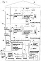
- Fig. 1 shows an overview of the communication system according to the invention for a house, which in the example shown in Fig. 1 of two end units, for. B. apartments, 10 and 12 consists.
- a first intelligent network termination device 14 In the first apartment is a first intelligent network termination device 14.
- a second intelligent network termination device 16 In the second end unit 12 is a second intelligent network termination device 16.
- the two intelligent network termination devices are connected via respective hubs 18, 20 with a central data bus 22, which in turn with a central Building communication and information server 24 is connected.
- the central building communication and information server is implemented as a separate element. He has the following functionalities according to the invention.
- the server can thus perform the switching of telephone calls.
- the switch can take place within the communication system, ie from one subscriber (connected to one device) to another subscriber (connected to another device), or via the server to the outside to the public telephone network.
- the switching services are similar to those of a telephone system.
- Data is also transmitted in the form of IP or other data packets.
- a subscriber exchanges data with another subscriber via the server.
- the server handles the switching, ie the routing, of the data.
- the server is used for the realization of administrative services, i. H. Services required to manage a building. This can be z. As the billing of telephone calls, data connections, the electricity bill, etc., or the monitoring of access to services and the granting of access rights.
- the server is used to process building-specific services. These services include e.g. Door services, security and surveillance services, HVAC or elevator control.
- the server can also perform the demultiplexing / multiplexing function for the external connection.
- the telephone connections from the public network are distributed among the individual subscribers. In general, one needs fewer telephone lines than there are subscribers, since it is statistically unlikely that all the participants will be on the same line at the same time. The more subscribers are connected to the communication system, the greater the multiplexing gain (number of subscribers in total) / (number of required telephone lines).
- the communication and information server is an advanced intelligent network termination device. However, he has the described special tasks, such as the administrative tasks or the broadband connection of the communication system to the access network to the network termination device.
- the server thus operates building-specific, while the network termination device is designed unit-specific.
- all functionalities of the communication and information server can also be in the first intelligent Network termination device 14 or be implemented in the second intelligent network termination device 16.
- the house 8 its own central building communication and information server, which is housed in a separate room of the house, for example, in the basement, or in a study in the house possibly present caretaker's dwelling.
- this room is also preferably a service terminal 26, via which the communication system according to the invention can be controlled, changed, supplemented or generally maintained.
- the central building communication and information server 24 is connected to a video camera 28 and optionally to other sensors 30 for monitoring the security of the home 8.
- HVAC heating, ventilation, air conditioning
- the central server is also connected to control the home air conditioner, as well as other functions such as the control of the blinds, etc., generally indicated by the symbols shown at 34 in FIG.
- the central server also has responsibilities with regard to the elevator control 36, the door communication, access control and mailbox monitoring 38 or the emergency call function 40 of the building in order to be able to alert a security service of each dwelling 10, 12.
- DECT Digital Enhanced Cordless Telephone
- DSL digital subscriber line
- x is a placeholder for a particular technology or for a particular method, where "A” would be asymmetric and "S” would be symmetric
- each end unit has its own intelligent network termination device.
- the central building communication and information server 24 may alternatively be integrated in the intelligent network termination device 14. Then the communication system according to the invention would consist only of the two intelligent network termination devices 14 and 16, which are interconnected via the central data bus 22. If the entire communication system has only two intelligent network termination devices, the central data bus can be directly connected to the central data bus without the use of the hubs 18, 20. However, as shown in Fig. 1, if a separate central building communication and information server 24 is provided which complies with the functionalities shown in the lower half of Fig. 1, then the intelligent network termination devices for the hubs 18, 20 must be connected to the server 24 are connected. In this case, the central building communication and information server also be expanded as necessary to the functionalities of the intelligent network termination devices 14, 16, so that a communication system is present, which has virtually three intelligent network termination devices 14, 16 and 24.
- Fig. 1 relates to a house 8 having two apartments 10, 12, the system according to the invention can be readily applied to a house with only offices or to a house with offices and apartments.
- the communication system according to the invention can also be applied to an apartment alone, so that the individual rooms are end units, such that for a home own communication system according to the invention is present, the intelligent network termination devices are arranged, for example, in the individual rooms of the apartment.
- the communication system according to the invention is not limited to being used only in a house.
- a distributed building complex of some sort.
- Such an interconnected distributed building complex could be, for example, a campus consisting of university buildings and residential buildings.
- An application of the communication system according to the invention to such a related distributed building complex is useful if the building complex, for example, is managed jointly.
- the communication system according to the invention can be used.
- a central building communication and information server 24 would be located, for example, in the building complex management center.
- Each individual building, ie Nordbau, Südbau, Haupt constitution, etc. would then have its own intelligent network termination device, which is connected to the central data bus via a hub.
- the individual floors of, for example, the North Building then would, as indicated in Fig. 7, with the intelligent network termination of the Nordbau connected so that a network branch has been achieved, which includes a Nordbau communication network for which a smart network termination of the Nordbau works as a central server, while this central server is in turn connected to the central server of the entire building complex.
- a hierarchical structure can be obtained.
- the actual implementation will depend on whether there is a lot of traffic within a building, or if this "internal" traffic is less significant than the traffic across the central server for the entire building complex.
- the individual parts of the distributed building complex need not be arranged in close proximity to each other. They may also be remote from each other, there must only be a branch from the central data bus to the remote part of the building complex. If the distances become greater, repeaters must be used, as known in the art, to regenerate the transmitted digital signals at distances determined by cable attenuation.
- the advantageous side of the concept of the invention shows the advantageous side of the concept of the invention, as it means a very high cost to put new data lines between buildings distant, and since inexpensive components, especially for large quantities, d. H. A lot of cables, many repeaters and many hubs, can certainly lead to a high price of the overall system, such that the communication system according to the invention has a huge competitive advantage over system solutions that deal with a variety of application-specific running parallel networks.
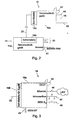
- Fig. 2 shows a schematic diagram of the communication network according to the invention.
- the communication network according to the invention comprises the central data bus 22, and the first intelligent network termination device, which consists of a network termination device 14a and an interface device 14b.
- the second network termination device which likewise consists of a network termination device 16a and an interface device 16b.
- the central data bus is not directly connected to the network termination device, but via the respective interface device.
- the interface devices 14b, 16b are configured to control the access of the respective network termination device to the central data bus, which does not involve deterministic access control and typically has a limited transmission capacity.
- the network termination devices include "on the output side" (if the part of the network termination device connected to the associated interface is considered as an input) various interfaces designated for the first network termination device 16a as 42, 44, 46, 48, which are the ones shown in FIG 1 represent functionalities shown.
- the network terminating device 14a, 14b also comprises a number of interfaces 50, which in principle may correspond to the interfaces 42 to 48, but in the first network terminating device 14 of Fig. 2, the peculiarity is that this network terminating device also has an interface 41 to the external network ,
- the first network termination device 14 in FIG. 2 is thus extended by functionalities of the central server 24 of FIG. 1 and accordingly may also include ports 26 to 40 of FIG.
- the second network termination device 16 thus serves as an interface for communication systems within an end unit (apartment / room / office).
- the intelligent network termination device from network termination device 16a and interface 16b thus summarizes standardized and common interfaces z.
- DECT voice, telecommunications applications, Internet and data services and in-house bus systems
- the network termination device itself can thus also as a so-called stand-alone device within a unit, for. As an office, operated.
- it provides via the interface device (eg 16b) an interface to the central data bus, which connects the network termination device to the other network termination device and provides access to home communication.
- the central data bus 22, which is preferably based on Ethernet, which is extended to a QoS-capable transmission protocol by means of the interface devices 14b, 16n, can be implemented on the physical level as an unshielded twisted-pair cable, as a shielded twisted-pair cable, as a fiber optic cable or as another medium be.
- various transmission methods / transport protocols may be used in principle for the present invention, which are suitable for a central data bus, such that they do not have their own deterministic access control, i. H. all subscribers are equal and access as desired, exhibiting and having limited data capacity
- Ethernet is favored for its affordability, flexibility, wide distribution and technical sophistication. Therefore, all subsequent embodiments refer to the preferred embodiment of the present invention where the central data bus is an IEEE 802.3 standard Ethernet data bus.
- the first network termination device 14 is extended as a communication and information server.
- the first network terminal 14a provides the link between the in-house network and the access network (access network) which multiplexes or service-processes the various data streams.
- interworking at the network and application level between the different networks / services is realized here.
- information on various in-house services is offered.
- the first network termination device thus corresponds to the second network termination device, with some server services still being able to be implemented for the communication network according to the invention, for example, if central QoS management of the interface devices, switching services or multiplex services are used.
- the first and second interface device (14b, 16b) of the first and second network termination device (14a, 16a) will be discussed in more detail below.
- Each of these interface devices (14b, 16b) may be constructed substantially the same and is also referred to as a QoS layer or QoS layer.
- Such an interface device takes over the control of the media access. This takeover ensures that the connected station can only transmit at certain times assigned to it and / or only a limited amount of data.
- This inventive control of the media access ensures that there are no collisions, d. that is, two or more stations can transmit, come in at the same time, and that no loss of data can thereby occur.
- the parameters for a connection include: minimum bandwidth, maximum delay, time intervals, maximum jitter. It should be noted that for a connection of the two interface devices concerned not all of the mentioned parameters but only at least one must be determined.
- FIG. 3 there is shown an intelligent network termination device again comprised of the access interface 16b and the network termination device 16a, which includes interfaces 42, 44, 46, 48 exemplified in Fig. 3, and optional interworking, not shown in Fig. 3 Units, such that traffic over the DECT interface 42 to the LAN connected to the Ethernet interface of the network terminating device 16a need not pass over the central data bus 22, but rather is handled “regionally” in the network terminating device 16a , For very reasonably priced However, embodiments can be dispensed with such "interworking" units, such that the traffic always runs on the central data bus 22.
- the network termination device 16a can also operate in stand-alone mode, such that interworking and mapping between DECT, Ethernet, in-house bus and ISDN is possible.
- the ISDN interface which can be present at an intelligent network termination device will be discussed in greater detail.
- the ISDN connection is routed via the QoS backbone, which is also referred to as tunneling.
- the ISDN interface in the network termination device operates in NT mode and feeds the terminals.
- the ISDN interface in the server operates in TE mode and is connected to a switching unit.
- the ISDN connection from INT is routed continuously to the exchange unit and not terminated on the way.
- the system works as so-called "S 0 extension".
- the network termination device uses the ISDN interface as access to the telephone network. Via this access can be telephoned and data can be transmitted.
- EIB / LON connection serial data is converted into EIB / LON raw data in an EIB / LON interface library.
- An EIB / LON service library provides access to the interface library as well as a TCP / IP driver and performs this Interworking between the two.
- Below the TCP / IP driver there may be different networks, for example the interface to the QoS backbone to transport the EIB / LON data between the server and the network termination device, a DECT interface or an Ethernet interface.
- An EIB access is thus as follows.
- the data from the EIB network are converted to serial data via an EIB serial gateway.
- the serial data are fed into the transmission network.
- This can be the QoS backbone, for example, or the DECT data interface or conventional Ethernet.
- the corresponding communication partner receives the data and can pass them on to a module for visualization and control (eg a webpad, notebook, organizer). This module can then send control data over the same path back to the EIB network.
- IP data can be routed through the QoS backbone.
- QoS-Data Another interface (QoS-Data) allows access to the QoS backbone with other data formats.
- Video data after being received from a video card or network, is tunneled over the QoS backbone. On the remote station, the data is fed back into the video card or into another network.
- a conversion of the DECT voice data to ISDN data is made. Then the treatment is the same as with ISDN.
- a conversion to TCP / IP format is made. Then the data is handled as usual in IP traffic.
- Fig. 4 shows a detailed representation of the various layers of the network termination device 14a including interface device 14b.
- interfaces 42, 46, 48 and 44 which are referred to in more detail in Fig. 4.
- interworking network 52 which allows direct traffic between the individual interfaces 42, 46, 48, 44.
- Interworking Services / Control 54 Above it is a layer labeled Interworking Services / Control 54.
- the interface device 14b is constructed analogously thereto and comprises, as a core element, the access control which performs the QoS management and is designated by 56.
- the interface device 14b also has a network layer 58 and a services / control layer 60.
- Fig. 5 is a schematic overview of the central data bus for a system of four network termination devices 62 to 65 and a communication server 66 is shown.
- the communication server 66 can serve two communication networks, namely the first communication network, which consists of communication server 66 and the network termination devices (NT) 63, 64, 65, and another communication network, which consists only of the Communication server 66 and the network termination device 62 consists.
- the central data bus does not necessarily have to be established wired, but also can be wireless.
- the central data bus is therefore not limited to a specific physical medium. It could therefore be implemented on the basis of the power grid or other in-house cable systems.
- Fig. 6 shows the protocol stack of the transport platform of the communication network according to the invention.
- the lowermost layer which is referred to as physical layer 70 in FIG. 6, represents the physical medium of the central data bus, which may be either a wired line, a radio link, or a fiber link.
- the transport protocol layer 71 which in the preferred embodiment of the present invention is implemented as an Ethernet transport protocol according to the IEEE 802.3 standard.
- the access of the network terminating device 14a to the transport protocol layer 71 takes place via the QoS layer 14b.
- the QoS layer controls access to the central data bus 22 so that each subscriber has sufficient network capacity.
- the requirements vary with the services used. For example, voice services require a short, consistent delay and guaranteed bandwidth.
- voice services require a short, consistent delay and guaranteed bandwidth.
- keeping a minimum delay is less important.
- the user desires a fair or guaranteed allocation of the bandwidth.
- the interface device 14b thus performs a preference of communication devices connected to specific interfaces in the end unit of the house in relation to other communication devices of the end unit of the house. To put it bluntly, it is unacceptable for a telephone service that too long delays occur, since a customary telephone communication is then no longer well possible. If, however, data is lost during transmission during the transmission, this does not immediately lead to a loss of communication. On the other hand, it is crucial in the data transfer of, for example, a file that no data loss occurs. For this it is less important that the data transfer takes place very fast.
- Such a classification can be made for all home services, so that, for example, an emergency call always has a very high priority, while it is irrelevant for the blind control or the heating control, whether the Data for these systems will be transmitted a few seconds sooner or later.
- the interface device 14b thus allocates the required system resources to the individual services.
- resource allocation is relatively clear, but it is complex for the more complicated case where multiple distributed units access a common medium.
- QoS control for such a system can be implemented.
- master-slave structures distributed QoS management or simple prioritization may be considered.
- the approaches differ in their performance, efficiency, protocol overhead, etc.
- the communication network according to the invention must also be protected against unauthorized access. For this reason, optionally suitable cryptographic methods can be used both at the level of the interface device and at a higher level up to the application in order to make it impossible or very difficult to falsify data or listen to data.
- the communication network according to the invention is optimally scalable and adaptable for any application, be it that it is about the selection of the medium for the central data bus, whether or not a network terminating device has interworking capability.
- a decentralized selection method (eg token passing architecture) is preferred over a central selection method (eg master-slave method) because of the superior reliability.
- a token runs, illustratively speaking, from one intelligent network termination device to the next intelligent network termination device.
- Each intelligent network termination device when in possession of the token, can transmit data on the central data bus.
- the functionality of token reception and token passing is performed by the interface device associated with the corresponding network termination device.
- the interface device also determines what amount of data each network termination device may transmit per token ownership, or whether a network termination device may send each token ownership, or perhaps only at z. For example, every tenth token ownership.
- the selection method used has the advantage that it is a deterministic method, that a bandwidth reservation can be guaranteed, that maximum latencies are guaranteed, that it is suitable for isochronous transmission, that it has a low complexity, and in particular that it is more selective because it is decentralized.
- Disadvantages of the decentralized selection method are overhead in the token passing, a limited but variable delay, so that the stations that have nothing to send can still receive a token or temporarily drop out of the logical ring, which can result in jitter it is particularly suitable for isochronous transmission and is poor for burst transmissions, and that expensive token management is available, for example, to regenerate a lost token.
- An advantage of the central selection method is that it is a deterministic method, that bandwidth reservation can be guaranteed, that latencies can be guaranteed, that it is very flexible according to the scheduling algorithm, and that any QoS arrangements can be guaranteed ,
- the disadvantage of the central selection method is that there is an overhead in succession through the query of the stations, that this method can become very complex depending on the scheduling algorithm, that it is very time-intensive when it is considered that a few thousand queries can take place per second, that it is at risk of failure, and that in case of overload or failure of the scheduler the entire Network is blocked.
- FIG. 7 it can be seen that a communication server, as has already been illustrated with reference to Fig. 5, can not only be part of a single communication network but can also be part of one or more further communication networks 81, 82. From Fig. 7, a further possible design of the communication network according to the invention is also apparent. Thus, it is shown in Fig. 7 that at the hub 18, to which the second intelligent network termination device (INT) 16 is connected, also other intelligent network termination devices 83 may be mounted.
- the hub designated by 20 in FIG. 1 is divided into a first hub 20b and a second hub 20a in FIG. 7, the intelligent network termination device 14 via these two hubs 20a, 20b and a secondary branch 22a, which also forms part of the central data bus 22 is connected to the communication server 24 via further hubs 84, 85.
- either directly intelligent network termination devices may be present, or other ancillary branches may be arranged, which lead, for example, to other parts of a distributed building complex.
- the token method as a decentralized selection method provides a controlled access with a token. It is completely decentralized. Alternatively, the token circulation can also be calculated and controlled from a central location, for example from the communication server. There are no collisions. The extent of the network is limited only by attenuation properties. If the cable lengths are too long, either repeaters can be used or hubs, which are not analog amplifiers, but regenerate the binary signals. The length limitation of the cable due to the damping thus exists in the case shown in FIG. 7 only in branch lines between two hubs, such as B. the branch line 22a or the line between the hub 18 and the hub 20b, etc.
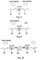
- FIG 8 shows schematically the transition from a token passing architecture 90 to another token passing architecture 91.
- Token passing describes a group of protocols that operate according to a similar method.
- the term "token passing" does not say anything about the performance of a process, but merely indicates a process by which a token is forwarded to grant a broadcasting right.
- Token-passing techniques include token bus, token ring, FDDI (Fiber Distributed Data Interface) or Rether.
- the link is referred to as gateway 92.
- the gateway could be, for example, a personal computer.
- Such a transition could be in a smart network termination device interconnecting two token passing networks located in the home 10 ( Figure 1). However, such transition may also be present between hub 20b and hub 18, when Fig. 10 is considered, to divide the central data bus into two bus substructures. This is advantageous when there is a relatively large amount of traffic within a bus substructure, but with relatively little traffic between the bus substructures. Then, each segment, ie the network 90 and the network 91, forms its own so-called domain, so that full bandwidth is available for traffic within the two domains.
- a transition between two networks referred to in FIG. 8 could also be present in the communication server 24 of FIG.
- the gateway 22 may consist of a standard PC equipped with two network cards. With not too strong traffic, which manifests itself in computing time for the gateway 92, the gateway 92 can participate as a normal station in traffic. However, there is a danger if the gateway 92 fails.
- Fig. 9 shows a transition between a token passing network 93 and a LAN 94.
- the transition between the networks 93 and 94 is in turn managed by a gateway 95, which may also be configured as a PC.
- a gateway 95 will be present in each intelligent network termination device to couple a local area network, for example in an office, to the central data bus 22, which is designed as a token-bus system.
- FIG. 10 shows the connection of two token passing systems 96, 97 via a respective gateway 98, 99 with a LAN 100.
- a structure could e.g.
- the communication network 81, 82 is also implemented as a token-passing network, the communication server 24 in turn participates in a LAN.
- a decentralized selection method is also preferred for the home communication system according to the invention, in order to ensure a higher reliability, in certain applications master-slave systems may also be used.
- a master allocates the requested system resources to the network termination devices by giving the individual network termination devices the rights to send.
- a network termination device may only transmit when prompted by the master.
- Each segment 101, 102 forms its own domain, so that the full bandwidth is available for each segment.
- the gateway 103 in Fig. 11 operates as a slave and only handles the routing between the network segments 101 and 102.
- the masters 104, 105 are independent of the Gateway installed in the networks 101 and 102, respectively.
- the gateway may consist of a standard PC, be implemented in a smart network termination device, or be a stand-alone device, requiring two network interfaces. If the traffic is not too heavy, this gateway can participate as a normal station in the master / slave process. However, there is a risk of non-availability of a network segment or traffic between 101 and 102 if the gateway 103 fails.
- FIG. 12 shows a gateway 106 between two master / slave systems 101, 102, but now the two master elements 104, 105 are integrated directly into the gateway 106. Here is the full bandwidth available in each subnet.
- the communication and information server 24 (FIG. 7, FIG. 1) will once again be discussed, which serves for the connection of the entire system to the external access network and, moreover, for the connection of the network to the individual building-specific units for building control and building monitoring is provided.
- the server serves as a concentrator within the distributed system, from which the central management and control of the home communication and home services takes place.
- the communications server service and management platform is used to visualize and manage the building-specific services and communication and information systems.
- the services are implemented distributed on the communication and information server as well as on the intelligent network termination devices.
- the service and management platform sits on the transport system for transmission. At the service platform level, service-specific interworking also takes place between the different networks.
- FIG. 13 shows an overview of the classification of the individual services in a protocol stack on the basis of the ISOOSI model.
- the OSI layer numbers are numbered from 1 to 7.
- Layers 2 through 4 of FIG. 13 relate to the in-house data bus transport platform.
- Layer 5 comprises basic communication services.
- the service connection relates to the transmission of connection information.
- the language service concerns the transmission of voice data.
- the video service concerns the transmission of video data.
- the control service relates to the transmission of control data.
- the data service relates to the general data transmission, for example WWW or FTP.
- the service system finally concerns the transmission of native information.
- the service telephone concerns voice communication, telephony and video telephony.
- the security service concerns security functions, for example an alarm system.
- the emergency call service concerns an emergency call or an alarm.
- the service door concerns the door communication.
- the service access control refers to the access control for the house or for the distributed building complex.
- the Domestic Services service refers to Facility Management, such as: As water, electric light, etc.
- the service transportation refers to in-house transport systems, such. As lifts, escalators, etc.
- the top layer number 7 contains the individual applications which are provided by the communication devices present in the end units.
- the intelligent Network Terminator integrates various communication systems (DECT, Ethernet, ISDN, in-house bus system) and enables interworking between different interfaces.
- the NT works as a central distributor within a unit (e.g., apartment or room).
- the Ethernet transport platform is based on a standardized, flexibly expandable in-house broadband transmission method with support for 10-1000 Mbit / s (shared medium or point-to-point) as in-house backbone.
- other transmission methods / protocols can be used with relatively simple adjustments (eg powerline, SDSL, wireless LAN).
- the communication system is at the same time a transport and service platform (service-transparent or service-specific transmission).
- the inventive concept also provides a considerable savings potential in the cabling, management and also in the devices used by the multiple use. This results in an additional cost savings through the multiplex gain on access to the access network (telecommunications and the Internet), so can eg a house via only one twisted pair cable (for the s.den DeutscheInstitut rent must be paid) broadband networked.
- a multimedia terminal allows access to the interfaces built into the intelligent network terminator (NT) and enables communication and information processing within a building.
- the multifunctional terminal can replace or supplement previous terminals.
- Ethernet for the central data bus
- Ethernet is preferred as a central data bus.
- constraints z. B. in the form of the use of an existing infrastructure another network cheaper, so it will be preferred in this particular case.
Landscapes
- Engineering & Computer Science (AREA)
- Signal Processing (AREA)
- Computer Networks & Wireless Communication (AREA)
- Automation & Control Theory (AREA)
- Multimedia (AREA)
- Computing Systems (AREA)
- Small-Scale Networks (AREA)
- Telephonic Communication Services (AREA)
- Data Exchanges In Wide-Area Networks (AREA)
Claims (12)
- Réseau de communication pour une maison (8), un appartement ou un bureau dans une maison (8) ou pour un immeuble partagé, pour relier entre eux au moins trois terminaux (10, 12) dans la maison, l'appartement, le bureau ou l'immeuble partagé, aux caractéristiques suivantes:un bus de données central (22) destiné à transmettre des données à communiquer entre les au moins trois terminaux (10, 12);un premier appareil de terminaison de réseau (14a) qui est prévu pour un premier terminal (10) et qui comporte des interfaces (50) pour des appareils de communication pouvant être disposés dans le premier terminal (10);un premier moyen d'interface (14b) associé au premier appareil de terminaison de réseau et disposé et réalisé entre le bus de données central (22) et le premier appareil de terminaison de réseau (14a), pour commander un accès du premier appareil de terminaison de réseau (14a) au bus de données central;un deuxième appareil de terminaison de réseau (16a) qui est prévu pour un deuxième terminal (12), et qui comporte des interfaces (42, 44, 46 48) pour des appareils de communication pouvant être disposés dans le deuxième terminal (12);un deuxième moyen d'interface (16b) associé au deuxième appareil de terminaison de réseau et disposé et réalisé entre le bus de données central (22) et le deuxième appareil de terminaison de réseau (16a), pour commander un accès du deuxième appareil de terminaison de réseau (16a) au bus de données central (22);un troisième appareil de terminaison de réseau (65) qui est prévu pour un troisième terminal, et qui comporte des interfaces pour des appareils de communication pouvant être disposés dans le troisième terminal;un troisième moyen d'interface associé au troisième appareil de terminaison de réseau et réalisé entre le bus de données central (22) et le troisième appareil de terminaison de réseau, pour commander un accès du troisième appareil de terminaison de réseau au bus de données central (22),le bus de données central étant un trajet de transmission utilisé en commun auquel peut être accédé par le premier, le deuxième ou le troisième appareil de terminaison de réseau sans tenir compte d'autres appareils de terminaison de réseau respectifs,le premier, le deuxième et le troisième moyen d'interface (14b, 16b) étant disposés pour commander l'accès du premier, du deuxième et du troisième appareil de terminaison de réseau au bus de données central de sorte que soient garantis, pour une communication entre le premier, le deuxième et le troisième appareil de terminaison de réseau par l'intermédiaire du bus de données central des paramètres de transmission garantis, etchaque appareil de terminaison de réseau ou chaque appareil de communication relié à l'appareil de terminaison de réseau étant disposé de manière à convenir lui-même avec le moyen d'interface (14b, 16b) associé à ce dernier des paramètres de transmission pour une transmission par l'intermédiaire du bus de données central pour obtenir une qualité de service adaptative.
- Réseau de communication selon la revendication 1, dans lequel le bus de données central (22) est un réseau Ethernet selon la norme IEEE 802.3, un réseau PLC, un réseau xDSL, un réseau câblé à large bande ou un réseau de radiocommunication à large bande.
- Réseau de communication selon la revendication 1 ou 2, dans lequel les interfaces (42, 44, 46, 48, 50) du premier, du deuxième ou du troisième appareil de terminaison de réseau (14a, 16a) comportent une interface qui est choisie parmi le groupe d'interfaces suivant: une interface pour un système de radiocommunication à large bande pour la transmission de voix et/ou de données, pour un système Ethernet, pour un système ISDN, pour un système POTS, pour un système à capteur/actionneur pour une commande domotique, pour un système à capteur/actionneur pour un système de surveillance de maison, pour un système PLC, pour un système de communication de porte et pour un système EIB.
- Réseau de communication selon l'une des revendications précédentes, dans lequel le premier appareil de terminaison de réseau (14a) est réalisé sous forme de serveur d'information et de communication central (24) et comporte, par ailleurs, une interface (41) pour un système de communication extérieur, pour permettre une liaison de communication de voix et de données entre les appareils de communication reliés aux appareils de terminaison de réseau (14a, 16a) et un abonné du système de communication extérieur.
- Réseau de communication selon la revendication 4, dans lequel l'interface (41) pour le système de communication extérieur est une interface ISDN, une interface xDSL à large bande, une interface pour un système de radiocommunication à large bande terrestre, un système de radiocommunication par satellite, un câble à fibre de verre, un réseau PLC externe ou un câble de cuivre à large bande.
- Réseau de communication selon l'une des revendications précédentes, dans lequel le bus de données est réalisé par une ligne bifilaire torsionnée non blindée, par une ligne bifilaire torsionnée blindée, par un câble à fibre de verre ou par un trajet de radiocommunication.
- Réseau de communication selon l'une des revendications précédentes, dans lequel au moins un appareil de terminaison de réseau (14a, 16a) est disposé de manière à permettre une communication entre les appareils de communication raccordés aux interfaces de ce dernier, sans que des données relatives à cette communication ne soient transmises à large bande par l'intermédiaire du bus de données central.
- Réseau de communication selon l'une des revendications précédentes, dans lequel le bus de données central (22) présente les caractéristiques suivantes:un segment principal qui est relié au premier appareil de terminaison de réseau;un noeud de communication (85, 84, 20b) pour chaque appareil de terminaison de réseau, les noeuds de communication étant disposés dans le segment principal; etun segment auxiliaire (22a) pour chaque appareil de terminaison de réseau, chaque appareil de terminaison de réseau pouvant communiquer, par l'intermédiaire du segment auxiliaire prévu pour ce dernier et le noeud de communication correspondant, avec le premier appareil de terminaison de réseau.
- Réseau de communication selon la revendication 1, dans lequel les moyens d'interface sont réalisés de manière à fixer comme paramètre de transmission, pour obtenir une qualité de service adaptative, au moins un paramètre du groupe de paramètres comprenant la réservation de largeur de bande, le temps de temporisation, la transmission périodique, la gigue et la commande d'accès.
- Réseau de communication selon la revendication 1 ou la revendication 9, dans lequel le premier, le deuxième et le troisième moyen d'interface sont disposés de manière à mettre en oeuvre un procédé de sélection central ou décentralisé pour commander l'accès à bus de données.
- Réseau de communication selon la revendication 10, dans lequel les moyens d'interface (14b, 16b) sont disposés de manière à mettre en oeuvre un procédé à 'token passing' (= passage de jeton) ou un procédé à principal/esclave.
- Réseau de communication selon l'une des revendications précédentes, dans lequel le bus de données central est modulable, quant à sa capacité de transmission de données, à une capacité de données requise.
Applications Claiming Priority (3)
| Application Number | Priority Date | Filing Date | Title |
|---|---|---|---|
| DE19938354 | 1999-08-13 | ||
| DE19938354 | 1999-08-13 | ||
| PCT/EP2000/007799 WO2001013575A2 (fr) | 1999-08-13 | 2000-08-10 | Systeme de communication interne, plate-forme de transport destinee a un systeme de communication interne et appareil de raccordement au reseau intelligent destine a un systeme de communication interne |
Publications (2)
| Publication Number | Publication Date |
|---|---|
| EP1219068A2 EP1219068A2 (fr) | 2002-07-03 |
| EP1219068B1 true EP1219068B1 (fr) | 2007-12-26 |
Family
ID=7918256
Family Applications (1)
| Application Number | Title | Priority Date | Filing Date |
|---|---|---|---|
| EP00956424A Expired - Lifetime EP1219068B1 (fr) | 1999-08-13 | 2000-08-10 | Systeme de communication interne, plate-forme de transport destinee a un systeme de communication interne et appareil de raccordement au reseau intelligent destine a un systeme de communication interne |
Country Status (5)
| Country | Link |
|---|---|
| US (1) | US20030037170A1 (fr) |
| EP (1) | EP1219068B1 (fr) |
| AU (1) | AU6837200A (fr) |
| DE (1) | DE50014879D1 (fr) |
| WO (1) | WO2001013575A2 (fr) |
Cited By (2)
| Publication number | Priority date | Publication date | Assignee | Title |
|---|---|---|---|---|
| DE102009058877A1 (de) * | 2009-12-18 | 2011-06-22 | Siemens Aktiengesellschaft, 80333 | Verfahren zum Prüfen von elektrischen Komponenten in einem Stromnetz, insbesondere in einem Gebäudestromnetz |
| DE102011077013A1 (de) * | 2011-06-06 | 2012-12-06 | S. Siedle & Söhne Telefon- und Telegrafenwerke OHG | Hauskommunikationsnetzwerk |
Families Citing this family (36)
| Publication number | Priority date | Publication date | Assignee | Title |
|---|---|---|---|---|
| DE60225443T2 (de) * | 2001-05-31 | 2009-03-26 | Omron Corp. | Sicherheitseinheit, steuerungsverkettungsverfahren, steuerungssystemsteuerverfahren und steuerungssystemüberwachungsverfahren |
| EP1396963B1 (fr) * | 2001-05-31 | 2010-01-27 | Omron Corporation | Systeme reseau de securite, esclaves de securite, controleur de securite, procede de communication, procede de collecte d'information et procede de surveillance dans un reseau de securite |
| CN1259601C (zh) * | 2001-05-31 | 2006-06-14 | 欧姆龙株式会社 | 从动设备、网络系统、从动设备的处理方法及设备信息收集方法 |
| WO2003001306A1 (fr) * | 2001-06-22 | 2003-01-03 | Omron Corporation | Systeme de reseau securise, esclave securise et controleur securise |
| CN1518816B (zh) * | 2001-06-22 | 2010-04-28 | 欧姆龙株式会社 | 安全网络系统及安全从动装置 |
| JP3912379B2 (ja) * | 2001-06-22 | 2007-05-09 | オムロン株式会社 | 安全ネットワークシステム及び安全スレーブ並びに通信方法 |
| DE10147772C1 (de) * | 2001-09-27 | 2003-09-11 | Siemens Ag | Verfahren zum Betreiben eines Übertragungssystems und Übertragungssystem in einem Energieversorgungsnetz |
| KR20050013158A (ko) * | 2002-06-24 | 2005-02-02 | 코닌클리케 필립스 일렉트로닉스 엔.브이. | 홈 네트워크 관리 |
| DE20211422U1 (de) | 2002-07-12 | 2002-10-10 | Grothe GmbH, 53773 Hennef | Multimediafähige Hauskommunikationsanlage |
| JP3988559B2 (ja) * | 2002-07-18 | 2007-10-10 | オムロン株式会社 | 通信システム、通信装置及び通信制御方法 |
| DE10241875B4 (de) * | 2002-09-09 | 2010-09-02 | Gira Giersiepen Gmbh & Co. Kg | Datenverarbeitungssystem |
| US7356372B1 (en) * | 2002-11-21 | 2008-04-08 | Global Network Security, Inc. | Facilities management system with programmable logic control |
| US7340314B1 (en) * | 2002-11-21 | 2008-03-04 | Global Network Security, Inc. | Facilities management system with local display and user interface |
| US20040260407A1 (en) * | 2003-04-08 | 2004-12-23 | William Wimsatt | Home automation control architecture |
| US20040242290A1 (en) * | 2003-05-29 | 2004-12-02 | Keeling Michael C. | Broadband communication system |
| DE10345737A1 (de) * | 2003-10-01 | 2005-04-21 | Merten Gmbh & Co Kg | System der Gebäudesystemtechnik und Verfahren zum Konfigurieren |
| DE10357422A1 (de) | 2003-12-04 | 2005-06-30 | Siemens Ag | Verfahren zur Übertragung von Daten über einen Datenbus sowie System und Gateway zur Durchführung des Verfahrens |
| US8028038B2 (en) | 2004-05-05 | 2011-09-27 | Dryden Enterprises, Llc | Obtaining a playlist based on user profile matching |
| ES2246702B2 (es) * | 2004-06-02 | 2007-06-16 | L & M DATA COMMUNICATIONS, S.A. | Servicio universal de telecomunicaciones ethernet. |
| DE102004028498A1 (de) * | 2004-06-11 | 2006-01-05 | Abb Patent Gmbh | Speisung einer Spannungsversorgungseinrichtung eines zweiten Bussystems, welches an ein erstes Bussystem angeschlossen ist |
| US7930422B2 (en) * | 2004-07-14 | 2011-04-19 | International Business Machines Corporation | Apparatus and method for supporting memory management in an offload of network protocol processing |
| US7533176B2 (en) * | 2004-07-14 | 2009-05-12 | International Business Machines Corporation | Method for supporting connection establishment in an offload of network protocol processing |
| US7493427B2 (en) * | 2004-07-14 | 2009-02-17 | International Business Machines Corporation | Apparatus and method for supporting received data processing in an offload of network protocol processing |
| DE102006050845B4 (de) | 2006-10-27 | 2018-10-31 | S. Siedle & Söhne Telefon- und Telegrafenwerke OHG | Hausanlage |
| EP2368229B1 (fr) * | 2008-12-18 | 2019-09-11 | Otis Elevator Company | Système et procédé de contrôle d'accès à un système de commande d'appareil de transport de personnes |
| DE102009050171A1 (de) * | 2009-10-21 | 2011-04-28 | Msr-Office Gmbh | Multifunktionseinheit |
| CN101848126A (zh) * | 2010-04-30 | 2010-09-29 | 中山大学 | 一种互动式控制智能家居设备的方法及家庭网络系统 |
| DE102010044346A1 (de) * | 2010-09-03 | 2012-03-08 | Rwe Rheinland Westfalen Netz Ag | Messstellennetzschnittstelleneinrichtung |
| DE102012003988A1 (de) * | 2012-02-28 | 2013-08-29 | Abb Ag | Systemkomponenten-Einbindung bei einem Haus-Kommunikationssystem |
| FR2987484B1 (fr) * | 2012-02-29 | 2014-04-04 | Gilbert Sabban | Systeme de controle d'acces pour ensemble immobilier |
| KR101600422B1 (ko) * | 2012-08-14 | 2016-03-21 | 주식회사 케이티 | 통화 단말과 다른 단말로 연속적으로 제공하는 감시 정보 서비스 방법 및 시스템 |
| KR101550062B1 (ko) | 2013-02-26 | 2015-09-04 | 주식회사 케이티 | M2m 디바이스의 제어권 공유 방법 및 이를 위한 m2m 서비스 플랫폼 |
| KR101441567B1 (ko) | 2013-03-05 | 2014-09-22 | 주식회사 케이티 | Ims 망을 통한 m2m 데이터 전달 방법 및 이를 위한 m2m 서비스 플랫폼 |
| CN104570962A (zh) * | 2013-10-10 | 2015-04-29 | 中兴通讯股份有限公司 | 一种家电远程控制方法、服务器及家电远程控制系统 |
| RU2686077C1 (ru) * | 2018-03-12 | 2019-04-24 | Закрытое акционерное общество "Неотелеком" | Универсальная система безопасности и связи |
| US20230280061A1 (en) * | 2022-03-01 | 2023-09-07 | Johnson Controls Tyco IP Holdings LLP | Building automation system with edge processing diversity |
Family Cites Families (9)
| Publication number | Priority date | Publication date | Assignee | Title |
|---|---|---|---|---|
| US5673395A (en) * | 1993-04-19 | 1997-09-30 | Kawakita; Jun | Process for constructing computer network system of tenant intelligent building |
| US5452291A (en) * | 1993-11-30 | 1995-09-19 | Panasonic Technologies, Inc. | Combination brouter and cluster controller |
| EP0689321A1 (fr) * | 1994-06-23 | 1995-12-27 | International Business Machines Corporation | Système d'allocation de bande passante pour l'intégralité d'un réseau à haute disponibilité |
| US6122279A (en) * | 1995-10-02 | 2000-09-19 | Virata Limited | Asynchronous transfer mode switch |
| US5886732A (en) * | 1995-11-22 | 1999-03-23 | Samsung Information Systems America | Set-top electronics and network interface unit arrangement |
| JP3660443B2 (ja) * | 1996-10-15 | 2005-06-15 | 株式会社東芝 | データ転送制御システム及び中継装置 |
| US5933427A (en) * | 1997-01-31 | 1999-08-03 | Edgepoint Networks, Inc. | Switch system employing a N:M switch circuit for routing packets among devices in a data communication network |
| US7027416B1 (en) * | 1997-10-01 | 2006-04-11 | Honeywell, Inc. | Multi tier wireless communication system |
| US6526581B1 (en) * | 1999-08-03 | 2003-02-25 | Ucentric Holdings, Llc | Multi-service in-home network with an open interface |
-
2000
- 2000-08-10 EP EP00956424A patent/EP1219068B1/fr not_active Expired - Lifetime
- 2000-08-10 US US10/071,005 patent/US20030037170A1/en not_active Abandoned
- 2000-08-10 WO PCT/EP2000/007799 patent/WO2001013575A2/fr not_active Ceased
- 2000-08-10 AU AU68372/00A patent/AU6837200A/en not_active Abandoned
- 2000-08-10 DE DE50014879T patent/DE50014879D1/de not_active Expired - Lifetime
Cited By (3)
| Publication number | Priority date | Publication date | Assignee | Title |
|---|---|---|---|---|
| DE102009058877A1 (de) * | 2009-12-18 | 2011-06-22 | Siemens Aktiengesellschaft, 80333 | Verfahren zum Prüfen von elektrischen Komponenten in einem Stromnetz, insbesondere in einem Gebäudestromnetz |
| US8850226B2 (en) | 2009-12-18 | 2014-09-30 | Siemens Aktiengesellschaft | Method for testing electrical components in main supply, in particular in building |
| DE102011077013A1 (de) * | 2011-06-06 | 2012-12-06 | S. Siedle & Söhne Telefon- und Telegrafenwerke OHG | Hauskommunikationsnetzwerk |
Also Published As
| Publication number | Publication date |
|---|---|
| EP1219068A2 (fr) | 2002-07-03 |
| US20030037170A1 (en) | 2003-02-20 |
| AU6837200A (en) | 2001-03-13 |
| WO2001013575A2 (fr) | 2001-02-22 |
| WO2001013575A3 (fr) | 2002-04-18 |
| DE50014879D1 (de) | 2008-02-07 |
Similar Documents
| Publication | Publication Date | Title |
|---|---|---|
| WO2001013575A2 (fr) | Systeme de communication interne, plate-forme de transport destinee a un systeme de communication interne et appareil de raccordement au reseau intelligent destine a un systeme de communication interne | |
| DE60202559T2 (de) | System und Verfahren zur Steuerung von Heimgeräten mittels einer Haustelefonleitung | |
| DE69923721T2 (de) | Lokales netzwerk von seriellen intelligenten zellen | |
| DE69925274T2 (de) | Verbindungsverfahren für internertdienste | |
| DE60119559T2 (de) | Überbrückungssystem zur zusammenarbeit von entfernten gerätegruppen | |
| DE69738560T2 (de) | Gerät zur Datenübertragungssteuerung, Relaisvorrichtung und Steuerungsvorrichtung für ein Haus-Netzwerk | |
| AT15530U1 (de) | Multikanal-videogegensprechanlagensystem mit zugang zu fortschrittlichen digitalen diensten | |
| EP2487839B1 (fr) | Système de chargement et de communication pour un véhicule automobile | |
| EP3575899B1 (fr) | Système d'automatisation, procédé de fonctionnement pour système d'automatisation et produit de programme informatique | |
| EP0795994A2 (fr) | Méthode pour la mise à disposition d'un système de câbles dans la région domestique | |
| EP1237250A2 (fr) | Système domestique | |
| DE4406505C2 (de) | Kommunikationssystem mit einer mit Personalcomputern und drahtlosen Fernsprechsystemen verbundenen Kommunikationsanlage | |
| DE602004007922T2 (de) | Verbindungssystem, Invers-Multiplexer, Datenübertragungsnetz, Verfahren und Computerprogramm | |
| DE10056469A1 (de) | Koppeleinrichtung und Koppelverfahren zur Kopplung von lokalen und globalen Netzwerken | |
| DE10315831A1 (de) | Haus-Netzwerk zur Übertragung von Steuerdaten für ein Hausautomationssystem | |
| DE10303477A1 (de) | Integriertes Licht- und Kommunikationssystem sowie Verfahren zur Nutzung desselben | |
| DE102010055187B4 (de) | Verfahren zum Übertragen von Informationen und Übermittlungseinheit | |
| EP0860956A2 (fr) | Pont entre lignes d'abonné et réseau de domotique | |
| DE202013011821U1 (de) | Schaltung für eine integrierte Steuerung und Verwaltung in Service-Netzwerken von intelligenten Gebäuden | |
| DE10249254A1 (de) | Aktiver Verteiler in einem Kommunikationsnetzwerk | |
| EP1710959B1 (fr) | Procédé de fonctionnement d'un système de bus pour un système de contrôle de bâtiment | |
| DE102021213161A1 (de) | Ladesystem | |
| DE102006017245B4 (de) | Datenübertragungsvorrichtung | |
| EP2434694B1 (fr) | Procédé de réponse de participants d'un système d'installation de bâtiment | |
| DE20009271U1 (de) | Telekommunikationsanlage |
Legal Events
| Date | Code | Title | Description |
|---|---|---|---|
| PUAI | Public reference made under article 153(3) epc to a published international application that has entered the european phase |
Free format text: ORIGINAL CODE: 0009012 |
|
| 17P | Request for examination filed |
Effective date: 20020204 |
|
| AK | Designated contracting states |
Kind code of ref document: A2 Designated state(s): AT BE CH CY DE DK ES FI FR GB GR IE IT LI LU MC NL PT SE |
|
| AX | Request for extension of the european patent |
Free format text: AL;LT;LV;MK;RO;SI |
|
| RAP1 | Party data changed (applicant data changed or rights of an application transferred) |
Owner name: FRAUNHOFER-GESELLSCHAFT ZUR FOERDERUNG DERANGEWAND |
|
| RBV | Designated contracting states (corrected) |
Designated state(s): DE GB |
|
| 17Q | First examination report despatched |
Effective date: 20061115 |
|
| RAP1 | Party data changed (applicant data changed or rights of an application transferred) |
Owner name: FRAUNHOFER-GESELLSCHAFT ZUR FOERDERUNG DER ANGEWAN |
|
| GRAP | Despatch of communication of intention to grant a patent |
Free format text: ORIGINAL CODE: EPIDOSNIGR1 |
|
| GRAS | Grant fee paid |
Free format text: ORIGINAL CODE: EPIDOSNIGR3 |
|
| GRAA | (expected) grant |
Free format text: ORIGINAL CODE: 0009210 |
|
| AK | Designated contracting states |
Kind code of ref document: B1 Designated state(s): DE GB |
|
| REG | Reference to a national code |
Ref country code: GB Ref legal event code: FG4D Free format text: NOT ENGLISH |
|
| REF | Corresponds to: |
Ref document number: 50014879 Country of ref document: DE Date of ref document: 20080207 Kind code of ref document: P |
|
| GBT | Gb: translation of ep patent filed (gb section 77(6)(a)/1977) |
Effective date: 20080401 |
|
| PLBE | No opposition filed within time limit |
Free format text: ORIGINAL CODE: 0009261 |
|
| STAA | Information on the status of an ep patent application or granted ep patent |
Free format text: STATUS: NO OPPOSITION FILED WITHIN TIME LIMIT |
|
| 26N | No opposition filed |
Effective date: 20080929 |
|
| PGFP | Annual fee paid to national office [announced via postgrant information from national office to epo] |
Ref country code: DE Payment date: 20150820 Year of fee payment: 16 Ref country code: GB Payment date: 20150824 Year of fee payment: 16 |
|
| REG | Reference to a national code |
Ref country code: DE Ref legal event code: R119 Ref document number: 50014879 Country of ref document: DE |
|
| GBPC | Gb: european patent ceased through non-payment of renewal fee |
Effective date: 20160810 |
|
| PG25 | Lapsed in a contracting state [announced via postgrant information from national office to epo] |
Ref country code: DE Free format text: LAPSE BECAUSE OF NON-PAYMENT OF DUE FEES Effective date: 20170301 Ref country code: GB Free format text: LAPSE BECAUSE OF NON-PAYMENT OF DUE FEES Effective date: 20160810 |