EP2148472A2 - Module de raccordement pour un réseau, procédé de mise en réseau de pièces et groupe de conteneurs doté de conteneurs mis en réseau - Google Patents
Module de raccordement pour un réseau, procédé de mise en réseau de pièces et groupe de conteneurs doté de conteneurs mis en réseau Download PDFInfo
- Publication number
- EP2148472A2 EP2148472A2 EP09009577A EP09009577A EP2148472A2 EP 2148472 A2 EP2148472 A2 EP 2148472A2 EP 09009577 A EP09009577 A EP 09009577A EP 09009577 A EP09009577 A EP 09009577A EP 2148472 A2 EP2148472 A2 EP 2148472A2
- Authority
- EP
- European Patent Office
- Prior art keywords
- connection
- network
- connection module
- client
- cable
- Prior art date
- Legal status (The legal status is an assumption and is not a legal conclusion. Google has not performed a legal analysis and makes no representation as to the accuracy of the status listed.)
- Granted
Links
Images
Classifications
-
- H—ELECTRICITY
- H04—ELECTRIC COMMUNICATION TECHNIQUE
- H04L—TRANSMISSION OF DIGITAL INFORMATION, e.g. TELEGRAPHIC COMMUNICATION
- H04L12/00—Data switching networks
- H04L12/28—Data switching networks characterised by path configuration, e.g. LAN [Local Area Networks] or WAN [Wide Area Networks]
- H04L12/40—Bus networks
- H04L12/40006—Architecture of a communication node
-
- H—ELECTRICITY
- H04—ELECTRIC COMMUNICATION TECHNIQUE
- H04L—TRANSMISSION OF DIGITAL INFORMATION, e.g. TELEGRAPHIC COMMUNICATION
- H04L41/00—Arrangements for maintenance, administration or management of data switching networks, e.g. of packet switching networks
-
- H—ELECTRICITY
- H04—ELECTRIC COMMUNICATION TECHNIQUE
- H04L—TRANSMISSION OF DIGITAL INFORMATION, e.g. TELEGRAPHIC COMMUNICATION
- H04L12/00—Data switching networks
- H04L12/28—Data switching networks characterised by path configuration, e.g. LAN [Local Area Networks] or WAN [Wide Area Networks]
- H04L12/42—Loop networks
Definitions
- the invention relates to a connection module for connecting at least one client, which can be controlled via a network protocol, to a local and / or global network with an erectable or suspendable housing, which is designed as an elongated cable channel, and with at least one first transfer interface for connecting the client.
- the invention further relates to a method for connecting at least one client, which can be controlled via a network protocol, in a room to a local and / or global network, in particular networking of mobile rooms and an accumulation of networked rooms, in particular in the form of exhibition stands or container settlements.
- Terminal modules and networks of this type are well known and usually have a star-shaped wiring to a central node in which a server is located. Using appropriate network components, such as a router or a switch, several networks in star topology can be interconnected.
- a fixed, slightly larger network typically requires copper cabling and, if a plurality of clients are used, active routers or switches that can only be established by a person skilled in the art.
- the object of the invention is to provide connection modules for a network, by means of which the network is simple, quick and inexpensive to build and dismantle and can be effectively constructed with as constant as possible or preferably increased security.
- connection module according to claim 1
- method according to claim 14 and a container housing according to claim 19.
- a connection module for connecting at least one client, which can be controlled via a network protocol, to a local and / or global network, with a deployable or suspendable housing, which is designed as an elongated cable channel, and with at least one first transfer interface for connecting the client, wherein the connection module has at least one connection device actively establishing a network connection between the network and the client via the first transfer interface and a data input connected to the connection device, and a data output for connection to the network and / or for establishing a series connection with a plurality of connection modules, wherein the Connection device and / or the network protocol through which the Communication is organized within the network, are designed such that the connected to the connection module client is addressable within the series circuit.
- the new network is now modular. This is the main advantage over the previously used, permanently laid building cabling with parallel cables from a central node of the network to the individual network components.
- connection module is essentially pre-configured and has all the active components so that it only connects to the network connection to the central node, i. must be connected to the server to provide in the appropriate room the connection options for the client or other components.
- Clients within the meaning of the invention are all devices which can be integrated into a network, for example communication devices such as computers, servers, printers, telephones or household appliances, for example, home intercoms, consumption meters or components of an alarm system.
- the transfer interface of the connection module provides an interface for connecting a client to the connection device.
- This interface can be a standardized connection socket, such as an RJ45 socket, to which one or more computers or telephones can be connected.
- the transfer interface may be a radio interface, for example a WLAN (Wireless Local Area Network) access point or a Bluetooth transceiver.
- the connection module can have further connection boxes for the or other clients and / or further devices of telecommunications and / or other electrical devices.
- a network protocol for example, the TCP / IP protocol can be used.
- connection module can be connected in series with other connection modules via a cable and connected to a network with the server.
- connection modules for this purpose, in particular offers a ring wiring with a simple ring or a double ring, wherein the connection modules are connected to each other in the annular as well as in all other configurations in series.
- the Connection modules have a corresponding interface for the connection, which can easily be used by non-technically trained personnel to integrate into the network.
- each connection module also has a data output in addition to the data input.
- connection modules have one or more active connection devices which are or are adapted to address the devices connected to the connection module.
- a connection device can be, for example, a switch, a router or another network-technical coupling element, up to a computer, in particular a server, for example a print server, or contain such a coupling element or a computer, which is integrated as a mini-computer in the connection module.
- These components may or may not be provided in the connection modules or in each of the connection modules.
- connection modules these sockets or plugs for the connection of fiber optic cables and / or copper cables as data input and data output, so that over bridging cable sections bi- or unidirectional series, star or ring cabling are possible.
- the particular advantage of the fiber optic cable is that a large amount of data is transferable, an electromagnetic decoupling compared to other parts of the network is achieved and an overvoltage protection is ensured.
- copper cables have the advantage that they are comparatively inexpensive in terms of material costs.
- the inventive connection of connection modules in series can be dispensed with a complex star wiring, in which each connection module is guided to a central node of the network. It should be noted that two or more series connection modules may be part of a ring or star topology of the network.
- connection module For connection of the active components or even for looping through the supply voltage, the connection module can be provided with a current input or output and have sockets to deliver the supplied current to electrical consumers in the room.
- the modular connection module is constructed with its housing in the form of an elongated cable channel so that it can be easily arranged in the room, for example, set up or suspended.
- the housing of the connection module as a piece of a cable channel, which may be a commercially available cable channel is formed.
- This cable channel section can easily in one. Space can be hung and, easily connect with other rooms, particularly preferably via a loose wiring.
- This loose wiring can run in adjacent cable duct sections, so that in the room, for example: adjacent to the intended location for suspending the: connection module passive, so empty or only provided with a power supply pieces of a cable channel are arranged.
- the modular, active connection module which contains the active components described above, can then be switched between the adjacent passive modules, ie hung in the space between the passive modules or connected via plug-in connections.
- the housing can be plugged together or connected to at least one end face with one or more other housings in the form of elongated, passive cable channels, to build a longer, especially room-length cable channel. If a room does not require cabling, a correspondingly long passive module can be interposed as a "dummy", which also has a cabling but no connection option for clients.
- connection device of the connection module actively establishes a network connection between the local or even global network and the client.
- the connection device and / or the network protocol, via which the communication is organized within the network are designed such that a client connected to the connection module can be addressed within the series connection.
- all network techniques known to those skilled in the art come into consideration, in particular a network management using the TCP / IP protocol is preferably used. But other protocols are possible as well, including a modified token ring network.
- connection module has easy-to-wire connections to the data input and output, allowing anyone to connect the connection module in a series connection without the risk of misconnection.
- the data input and data output can be designed as a socket or plug, wherein for connecting two connection modules, a cable can bridge a plug of a first connection module with a socket of the connection module considered in the direction of the series connection.
- a cable end can also be led out of the housing at each side, wherein a first cable end is designed as a data input and a second cable end as a data output with a corresponding interface at its free end.
- these cable ends can be so long that they are sufficient without extensions to build up the series connection.
- the connection modules have small, preferably in the winding spring-loaded cable reels, so that a cable stub in the desired length can be pulled out.
- connection module can have a plurality of data inputs and / or data outputs, which can be designed as plug-in connections and / or as cable ends.
- more lines of building services especially power line with high-voltage or low-voltage occupancy can be connected. This is particularly useful to build a power supply also via the modular system of connection modules.
- Other communication channels such as telephone lines or data from a home phone system can be built on parallel, constructed in the same way connections.
- the plugs or sockets for the construction of the wiring correspond to the usual standards, in the case of data cabling in particular the standards of message transmission.
- a fiber optic cabling can also be built by laymen.
- the different data streams can of course also be transmitted via a common cable, namely the data cable.
- a common cable namely the data cable.
- each sub-signal can be modulated onto a carrier frequency assigned to it, so that at least one demodulation device is provided at the point of the feed in a modulation device and in the modular connection module.
- the signal is then separated from the data stream and optionally forwarded to the client located in the room after reading the addressing.
- a common data stream can be used, the individual signal components are then separated from each other via the network protocol.
- each connection module may have a separate power supply, which comprises a connectable to an external power supply cable.
- the external socket is preferably located in the room in which the connection module is arranged. With the voltage of the external socket, at least one arranged in the housing, externally accessible socket can be supplied with a supply voltage.
- a fiber optic network When using a fiber optic network, it can be configured to be ring-shaped to allow bidirectional traffic. This allows data traffic to be reversed if the data link is disrupted, either through damage or plugging a port module through expansion or downsizing of the network To maintain direction. Only the network performance is briefly affected by the reverse data flow in the short term, so that the normal user will hardly notice.
- each connection module can be provided with an error detection, which recognizes on the basis of the signal transit times to the server or by other usual techniques, if the data traffic is interrupted in one direction.
- a corresponding error message which may contain, for example, in combination with an identification or position specification of the respective connection module, the information in which direction is sent in unidirectional data traffic, the server or any client Use an appropriate evaluation program to easily and quickly determine where the line interruption occurred.
- connection modules can be connected to the clients within the room via all known methods.
- the connection module in addition to a wiring, which is preferably designed as a free cable within the room, also a conventional wireless router to set up a wireless network around the connection module or a Bluetooth transceiver for establishing a wireless network based on Bluetooth standards.
- a wiring which is preferably designed as a free cable within the room
- a conventional wireless router to set up a wireless network around the connection module or a Bluetooth transceiver for establishing a wireless network based on Bluetooth standards.
- infrared communication or other known transmission modes are also possible.
- the terminal module may include a Network Termination for Basic Rate Access (NTBA), a splitter for splitting the telephone signal into a Digital Subscriber Line (DSL) signal and an Integrated Services Digital Network (ISDN) signal or an analog telephone signal or also have a phone anläge.
- NTBA Network Termination for Basic Rate Access
- DSL Digital Subscriber Line
- ISDN Integrated Services Digital Network
- a network in particular as a ring network, can now be constructed in a particularly simple manner. This is particularly suitable for cabling of mobile spaces, but can also be used for short or long-term cabling of living or office space or similar open spaces, such as exhibition stands, or closed spaces, such as containers.
- the modular connection module is simply placed or suspended in the respective room, then the loop closed by the connection with adjacent connection modules or the server. Dynamic allocation in IP addresses can then dynamically integrate the connected clients into the Dynamic Host Configuration Protocol (DHCP) network.
- DHCP Dynamic Host Configuration Protocol
- the ring line is simply interrupted at one point and another connection module, possibly using further cable segments, is interposed.
- a server may be arranged, but in particular smaller networks but also a network of equal clients can be realized.
- the server or one the peer clients may be connected to another network via an appropriate interface, which may be, for example, the Internet as a global network, a World Area Network (WAN) of an organizational unit or even a local area network (LAN) of a provider.
- WAN World Area Network
- LAN local area network
- each stand is connected to at least one modular connection module to a ring network within a trade fair hall, a server integrated in the ring is then either directly connected to the Internet or communicates with the LAN of the trade fair company.
- connection modules inventive method mobile rooms or exhibition stands are wired, can be provided in each room a at least from one room side to the opposite room side reaching cable section, which is formed by a continuous cable or more, connected in series cables, wherein when building or subdivision of the rooms, the cable sections the individual rooms are interconnected or connected to each other with the interposition of a connection module.
- Another advantage over the usual network technology is the fact that the active components are arranged in space in the modular connection module. This can be provided with a heat dissipation, which can be formed, for example, by one or more fans, so that the reliability due to the avoidable overheating compared to small, uncooled in a separate housing routing or coupling components is increased.
- connection modules can be ready-made ready in various stages, so that by replacing the module easily the capacity of the network can be increased in a room or the network can be adapted to other requirements.
- the modularity Finally, the reusability of the wiring is also possible, as the connection modules can easily be removed from the room and used for a different purpose. Even when assembling and dismantling exhibition stands, containers or other mobile application areas, the individual modules can be easily installed and removed to adapt the cabling and the network to the new conditions.
- a preferred application of the technique according to the invention is the cabling of office containers.
- the container can be provided with one or more modules, which can not be bridged with included in the network container within the container settlement by pulling network with cables inside or outside of the container.
- the ring can simply be dissolved and a new container integrated.
- a network technician was necessary to locate the affected branch of the wiring and removed or relocated in additional container or container with increased network requirements in a container additional cables. This can now be eliminated by the invention.
- the invention proposes a method for connecting at least one client controllable via a network protocol in a room to a local and / or global network in which at least one connection module of the type described above is installed or suspended in the room, at least via the data input the connection device actively establishes a network connection between the network and the client via the first transfer interface and the connection device and / or the network protocol via which the communication is organized within the network, addressed to the client connected to the connection module within the series circuit.
- connection module is connected in series with a server and / or further connection modules.
- the inventive method is used in particular for networking a plurality of rooms with one or more central servers, wherein at least one connection module is arranged in each room and the connection modules are connected in series via a completely exposed cable connection and / or at least partially via a fixed wiring . can be.
- a connection module can be connected to the server or the further connection module via a fiber-optic cable designed as a single cable or as a double cable, wherein the connection modules can preferably be networked together to form a single or double-barreled ring.
- the fiber optic cable is connected to the data input of a connection module and the data output of another connection module or a server and connected to close the ring, the last connection module with its data output to a data input of the server.
- client computers and other devices of the data processing are connected to a server via the connection module.
- At least one further cable connection can be connected in a star-shaped or annular manner to the connection module. Furthermore, and in particular signals for a telephone connection or a door entry system can be transmitted via this additional cable connection.
- connection module can also be equipped with a telephone system, a splitter for sharing an ISDN and a DSL signal.
- a cable section extending at least from one room side to the opposite room side is preferably provided in each room, that of a continuous cable or several, in series switched cables is formed, wherein in the construction or subdivision of the rooms, the cable sections of the individual rooms are interconnected or connected to each other with the interposition of a connection module.
- connection module with which they are connected in series, or , if no connection module is provided in this room, are connected to each other via a jumper cable.
- the cable pieces may on the one hand be firmly connected to the space and on the other hand have a free end which can be pulled out against the force of a return spring from a receptacle, in particular a winding device.
- the cable sections may be fixedly connected to the connection module, so that initially for wiring a room, the one or more connection modules are introduced into the room and then the cable sections of the connection modules of adjacent rooms are connected together in a series circuit.
- the rooms can be wired with a data cable and telephone signals and / or signals of other functional devices, in particular a door entry system, either via the data cable as a data stream according to or another protocol of the network connection coded or transmitted as an additional signal on another carrier frequency.
- the signals can be separated from the data signals by a modulation / demodulation device of the connection module.
- the connection module is prepared accordingly for the connection of the further functional devices.
- the data traffic over a fiber optic double line is preferably bidirectional in the context of a ring network.
- the data transmission can take place unilaterally away from the fault location, whereby the connection modules, with only one-sided reception, for locating the fault to a central office, in particular the server, reporting the data reception direction from which they receive data.
- connection module of the type described above for integrating mobile spaces with clients, in particular spatially limited exhibition stands or containers in a computer network, wherein in each space at least one connection module is arranged, the connection modules with each other and with a server according to the method are connected according to one of the preceding claims and the clients are connected to the connection module.
- a container settlement can be set up with a plurality of containers stacked next to and / or one above the other, in which at least one connection module of the type described above is arranged in each container and the connection modules are connected in series, in particular to a closed ring are connected together.
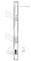
- connection module uses a piece of a cable duct as a housing. It is herbei a commercial cable channel, the housing can also take any other configuration.
- the case has a power supply on the left side and has jacks on the front for connecting clients.
- This can be a conventional socket 5 for connection to a supply current, an RJ45 network socket 4 or a telephone socket 6.
- Active network components provide a power supply 1 for transforming the supply current, an outcoupling 2 of the optical signal into the optical fiber, and a switch 3 for addressing the clients.
- the invention is not restricted to the components described above.
- An essential basic idea is the transformation of active and / or passive network components into the modular connection module, which can be marketed and reused as an easily transportable element which can be built up in different configurations. This distinguishes itself substantially from the previously sold, commercially available network components in a separate housing, since these must be integrated manually or through complex installation routines in the network, which regularly requires the use of a network engineer and reduces the reliability.
Landscapes
- Engineering & Computer Science (AREA)
- Computer Networks & Wireless Communication (AREA)
- Signal Processing (AREA)
- Small-Scale Networks (AREA)
- Mobile Radio Communication Systems (AREA)
Applications Claiming Priority (2)
| Application Number | Priority Date | Filing Date | Title |
|---|---|---|---|
| DE200820000099 DE202008000099U1 (de) | 2008-07-24 | 2008-07-24 | Anschlussmodul für ein Netzwerk und Containersiedlung mit vernetzten Containern |
| DE200810002966 DE102008002966A1 (de) | 2008-07-24 | 2008-07-24 | Anschlussmodul für ein Netzwerk, Verfahren zum Vernetzen von Räumen, Containersiedlung mit vernetzten Containern |
Publications (3)
| Publication Number | Publication Date |
|---|---|
| EP2148472A2 true EP2148472A2 (fr) | 2010-01-27 |
| EP2148472A3 EP2148472A3 (fr) | 2011-03-09 |
| EP2148472B1 EP2148472B1 (fr) | 2015-09-16 |
Family
ID=41288917
Family Applications (1)
| Application Number | Title | Priority Date | Filing Date |
|---|---|---|---|
| EP09009577.9A Active EP2148472B1 (fr) | 2008-07-24 | 2009-07-23 | Module de raccordement pour un réseau, procédé de mise en réseau de pièces et groupe de conteneurs doté de conteneurs mis en réseau |
Country Status (1)
| Country | Link |
|---|---|
| EP (1) | EP2148472B1 (fr) |
Cited By (1)
| Publication number | Priority date | Publication date | Assignee | Title |
|---|---|---|---|---|
| CN113154308A (zh) * | 2021-01-05 | 2021-07-23 | 平高集团有限公司河北雄安综合能源科技分公司 | 一种多功能信息杆柱 |
Citations (6)
| Publication number | Priority date | Publication date | Assignee | Title |
|---|---|---|---|---|
| DE19709827A1 (de) | 1997-02-27 | 1998-09-10 | Mannesmann Ag | Vorrichtung zur Fernsteuerung oder Fernmeldung über ein Mobilfunknetz |
| DE19836593A1 (de) | 1998-08-12 | 2000-02-17 | Siemens Ag | Datenerfassungs- und Übermittlungseinrichtung |
| GB2384604A (en) | 2002-01-23 | 2003-07-30 | Walter Blackburn | Remote property monitoring system using mobile phone text messaging |
| DE102004013428A1 (de) | 2004-03-18 | 2005-10-13 | Infineon Technologies Ag | Datenzugangsvorrichtung |
| GB2420645A (en) | 2004-11-25 | 2006-05-31 | Vodafone Plc | Communication module for connecting a computer to a network including a processor that allows the module to act independently |
| DE102008002966A1 (de) | 2008-07-24 | 2010-04-15 | Frank Fürstenau | Anschlussmodul für ein Netzwerk, Verfahren zum Vernetzen von Räumen, Containersiedlung mit vernetzten Containern |
Family Cites Families (2)
| Publication number | Priority date | Publication date | Assignee | Title |
|---|---|---|---|---|
| DE10011121A1 (de) | 2000-03-09 | 2001-09-27 | Alcatel Sa | Netzabschlusseinrichtung und Verfahren zum Filtern von Signalen |
| US6993417B2 (en) * | 2001-09-10 | 2006-01-31 | Osann Jr Robert | System for energy sensing analysis and feedback |
-
2009
- 2009-07-23 EP EP09009577.9A patent/EP2148472B1/fr active Active
Patent Citations (6)
| Publication number | Priority date | Publication date | Assignee | Title |
|---|---|---|---|---|
| DE19709827A1 (de) | 1997-02-27 | 1998-09-10 | Mannesmann Ag | Vorrichtung zur Fernsteuerung oder Fernmeldung über ein Mobilfunknetz |
| DE19836593A1 (de) | 1998-08-12 | 2000-02-17 | Siemens Ag | Datenerfassungs- und Übermittlungseinrichtung |
| GB2384604A (en) | 2002-01-23 | 2003-07-30 | Walter Blackburn | Remote property monitoring system using mobile phone text messaging |
| DE102004013428A1 (de) | 2004-03-18 | 2005-10-13 | Infineon Technologies Ag | Datenzugangsvorrichtung |
| GB2420645A (en) | 2004-11-25 | 2006-05-31 | Vodafone Plc | Communication module for connecting a computer to a network including a processor that allows the module to act independently |
| DE102008002966A1 (de) | 2008-07-24 | 2010-04-15 | Frank Fürstenau | Anschlussmodul für ein Netzwerk, Verfahren zum Vernetzen von Räumen, Containersiedlung mit vernetzten Containern |
Non-Patent Citations (2)
| Title |
|---|
| "100% Verfügbarkeit für Ihre IP-Telefonie und Power-over-LAN in Kategorie 6/7 Netzen mit Isabel*1000-TP", ISABEL 1000 TP DAFÜR GMBH, 6 May 2008 (2008-05-06), pages 1 - 2, XP003026795 |
| KAUFFELS F-J: "Lokale Netze Grundlagen Standards Perspektiven Siebte, aktualisierte und erweiterte Auflage", 1995, DATACOM BUCHVERLAG, ISBN: 3-89238-109-7, pages: 354 - 382, XP003026796 |
Cited By (1)
| Publication number | Priority date | Publication date | Assignee | Title |
|---|---|---|---|---|
| CN113154308A (zh) * | 2021-01-05 | 2021-07-23 | 平高集团有限公司河北雄安综合能源科技分公司 | 一种多功能信息杆柱 |
Also Published As
| Publication number | Publication date |
|---|---|
| EP2148472B1 (fr) | 2015-09-16 |
| EP2148472A3 (fr) | 2011-03-09 |
Similar Documents
| Publication | Publication Date | Title |
|---|---|---|
| DE69938111T2 (de) | Lokales netzwerk von seriellen intelligenten zellen | |
| EP1219068B1 (fr) | Systeme de communication interne, plate-forme de transport destinee a un systeme de communication interne et appareil de raccordement au reseau intelligent destine a un systeme de communication interne | |
| EP2351291B1 (fr) | Appareil de transmission de données | |
| EP2148472B1 (fr) | Module de raccordement pour un réseau, procédé de mise en réseau de pièces et groupe de conteneurs doté de conteneurs mis en réseau | |
| EP2332286B1 (fr) | Unité de connexion pour câbles de raccordement de réseaux d'alimentation sur ethernet | |
| EP1792438B1 (fr) | Systeme de communication, element de repartition et appareil reseau | |
| EP2719129B1 (fr) | Reseau de communication de domotique | |
| WO2003081739A1 (fr) | Systeme d'information domestique et de batiment | |
| DE102008002966A1 (de) | Anschlussmodul für ein Netzwerk, Verfahren zum Vernetzen von Räumen, Containersiedlung mit vernetzten Containern | |
| DE202008000099U1 (de) | Anschlussmodul für ein Netzwerk und Containersiedlung mit vernetzten Containern | |
| EP2606611B1 (fr) | Appareil d'installation avec couplage de données universel dans la technique d'équipement des bâtiments et dispositifs avec de tels appareils d'installation | |
| DE69924285T3 (de) | Verfahren zur verteilung und übermittlung von kommunikations- und multimediasignalen sowie signalverteilungseinrichtung zur übermittlung der kommunikations- und multimediasignale | |
| DE69937693T2 (de) | Drahtloses lokales verteilungssystem unter benutzung von standardstromleitungen | |
| DE102015220422A1 (de) | System und Verfahren zur redundanten Anbindung an ein Backbone-Netzwerk sowie ein in diesem System einsetzbarer Uplink-Knoten | |
| DE10303477A1 (de) | Integriertes Licht- und Kommunikationssystem sowie Verfahren zur Nutzung desselben | |
| DE19842447A1 (de) | Steckverbindersystem für eine Telekommunikations-Anschlußdose oder für ein Verteiler-Steckfeld | |
| DE10152263B4 (de) | Lokales integriertes Telefon- und Datennetz | |
| DE202009000673U1 (de) | Ethernet-Koppelgerät für die Gebäudeautomation | |
| DE20211422U1 (de) | Multimediafähige Hauskommunikationsanlage | |
| DE10050290B4 (de) | Vorrichtung zum Endgeräteanschluss | |
| EP2640156B1 (fr) | Réseau radio doté d'une réception de puissance moindre et procédé de fonctionnement d'un tel réseau radio | |
| EP1509004B1 (fr) | Procédé d'operation de deux sous-réseaux ayant des caracteristiques d'un bus et réseau correspondant | |
| DE202005019524U1 (de) | Vorrichtung zur Vernetzung elektrischer Sensoren und/oder Aktoren | |
| DE10160658A1 (de) | Vorrichtung und Verfahren zum Verbinden eines Endgerätes | |
| DE102010055187A1 (de) | Verfahren zum Übertragen von Informationen und Übermittlungseinheit |
Legal Events
| Date | Code | Title | Description |
|---|---|---|---|
| PUAI | Public reference made under article 153(3) epc to a published international application that has entered the european phase |
Free format text: ORIGINAL CODE: 0009012 |
|
| AK | Designated contracting states |
Kind code of ref document: A2 Designated state(s): AT BE BG CH CY CZ DE DK EE ES FI FR GB GR HR HU IE IS IT LI LT LU LV MC MK MT NL NO PL PT RO SE SI SK SM TR |
|
| AX | Request for extension of the european patent |
Extension state: AL BA RS |
|
| TPAC | Observations filed by third parties |
Free format text: ORIGINAL CODE: EPIDOSNTIPA |
|
| RIC1 | Information provided on ipc code assigned before grant |
Ipc: H04L 12/40 20060101AFI20091119BHEP Ipc: H04L 12/42 20060101ALN20100805BHEP Ipc: H02G 3/02 20060101ALI20100805BHEP Ipc: H04L 29/12 20060101ALI20100805BHEP |
|
| PUAL | Search report despatched |
Free format text: ORIGINAL CODE: 0009013 |
|
| AK | Designated contracting states |
Kind code of ref document: A3 Designated state(s): AT BE BG CH CY CZ DE DK EE ES FI FR GB GR HR HU IE IS IT LI LT LU LV MC MK MT NL NO PL PT RO SE SI SK SM TR |
|
| AX | Request for extension of the european patent |
Extension state: AL BA RS |
|
| 17P | Request for examination filed |
Effective date: 20110908 |
|
| RAP1 | Party data changed (applicant data changed or rights of an application transferred) |
Owner name: YELLOW NETCOM GMBH & CO. KG Owner name: MUENSTER, JOSEF |
|
| RIN1 | Information on inventor provided before grant (corrected) |
Inventor name: MUENSTER, JOSEF Inventor name: YELLOW NETCOM GMBH & CO. KG |
|
| RAP1 | Party data changed (applicant data changed or rights of an application transferred) |
Owner name: YELLO NETCOM GMBH Owner name: MUENSTER, JOSEF |
|
| RIN1 | Information on inventor provided before grant (corrected) |
Inventor name: MUENSTER, JOSEF Inventor name: YELLO NETCOM GMBH |
|
| 17Q | First examination report despatched |
Effective date: 20130225 |
|
| TPAA | Information related to observations by third parties modified |
Free format text: ORIGINAL CODE: EPIDOSCTIPA |
|
| GRAP | Despatch of communication of intention to grant a patent |
Free format text: ORIGINAL CODE: EPIDOSNIGR1 |
|
| TPAC | Observations filed by third parties |
Free format text: ORIGINAL CODE: EPIDOSNTIPA |
|
| RIC1 | Information provided on ipc code assigned before grant |
Ipc: H04L 29/12 20060101ALI20150302BHEP Ipc: H04L 12/40 20060101AFI20150302BHEP Ipc: H02G 3/02 20060101ALI20150302BHEP Ipc: H04L 12/42 20060101ALN20150302BHEP Ipc: H04L 12/24 20060101ALN20150302BHEP |
|
| INTG | Intention to grant announced |
Effective date: 20150325 |
|
| GRAS | Grant fee paid |
Free format text: ORIGINAL CODE: EPIDOSNIGR3 |
|
| GRAA | (expected) grant |
Free format text: ORIGINAL CODE: 0009210 |
|
| DIN1 | Information on inventor provided before grant (deleted) | ||
| AK | Designated contracting states |
Kind code of ref document: B1 Designated state(s): AT BE BG CH CY CZ DE DK EE ES FI FR GB GR HR HU IE IS IT LI LT LU LV MC MK MT NL NO PL PT RO SE SI SK SM TR |
|
| REG | Reference to a national code |
Ref country code: GB Ref legal event code: FG4D Free format text: NOT ENGLISH |
|
| RIN1 | Information on inventor provided before grant (corrected) |
Inventor name: FUERSTENAU, FRANK Inventor name: MUENSTER, JOSEF |
|
| REG | Reference to a national code |
Ref country code: CH Ref legal event code: EP |
|
| REG | Reference to a national code |
Ref country code: IE Ref legal event code: FG4D Free format text: LANGUAGE OF EP DOCUMENT: GERMAN |
|
| REG | Reference to a national code |
Ref country code: AT Ref legal event code: REF Ref document number: 750547 Country of ref document: AT Kind code of ref document: T Effective date: 20151015 |
|
| REG | Reference to a national code |
Ref country code: DE Ref legal event code: R096 Ref document number: 502009011574 Country of ref document: DE |
|
| REG | Reference to a national code |
Ref country code: CH Ref legal event code: NV Representative=s name: R.A. EGLI AND CO, PATENTANWAELTE, CH |
|
| REG | Reference to a national code |
Ref country code: NL Ref legal event code: FP |
|
| PG25 | Lapsed in a contracting state [announced via postgrant information from national office to epo] |
Ref country code: LT Free format text: LAPSE BECAUSE OF FAILURE TO SUBMIT A TRANSLATION OF THE DESCRIPTION OR TO PAY THE FEE WITHIN THE PRESCRIBED TIME-LIMIT Effective date: 20150916 Ref country code: NO Free format text: LAPSE BECAUSE OF FAILURE TO SUBMIT A TRANSLATION OF THE DESCRIPTION OR TO PAY THE FEE WITHIN THE PRESCRIBED TIME-LIMIT Effective date: 20151216 Ref country code: FI Free format text: LAPSE BECAUSE OF FAILURE TO SUBMIT A TRANSLATION OF THE DESCRIPTION OR TO PAY THE FEE WITHIN THE PRESCRIBED TIME-LIMIT Effective date: 20150916 Ref country code: LV Free format text: LAPSE BECAUSE OF FAILURE TO SUBMIT A TRANSLATION OF THE DESCRIPTION OR TO PAY THE FEE WITHIN THE PRESCRIBED TIME-LIMIT Effective date: 20150916 Ref country code: GR Free format text: LAPSE BECAUSE OF FAILURE TO SUBMIT A TRANSLATION OF THE DESCRIPTION OR TO PAY THE FEE WITHIN THE PRESCRIBED TIME-LIMIT Effective date: 20151217 |
|
| REG | Reference to a national code |
Ref country code: LT Ref legal event code: MG4D |
|
| PG25 | Lapsed in a contracting state [announced via postgrant information from national office to epo] |
Ref country code: SE Free format text: LAPSE BECAUSE OF FAILURE TO SUBMIT A TRANSLATION OF THE DESCRIPTION OR TO PAY THE FEE WITHIN THE PRESCRIBED TIME-LIMIT Effective date: 20150916 Ref country code: HR Free format text: LAPSE BECAUSE OF FAILURE TO SUBMIT A TRANSLATION OF THE DESCRIPTION OR TO PAY THE FEE WITHIN THE PRESCRIBED TIME-LIMIT Effective date: 20150916 |
|
| PG25 | Lapsed in a contracting state [announced via postgrant information from national office to epo] |
Ref country code: IT Free format text: LAPSE BECAUSE OF FAILURE TO SUBMIT A TRANSLATION OF THE DESCRIPTION OR TO PAY THE FEE WITHIN THE PRESCRIBED TIME-LIMIT Effective date: 20150916 Ref country code: EE Free format text: LAPSE BECAUSE OF FAILURE TO SUBMIT A TRANSLATION OF THE DESCRIPTION OR TO PAY THE FEE WITHIN THE PRESCRIBED TIME-LIMIT Effective date: 20150916 Ref country code: IS Free format text: LAPSE BECAUSE OF FAILURE TO SUBMIT A TRANSLATION OF THE DESCRIPTION OR TO PAY THE FEE WITHIN THE PRESCRIBED TIME-LIMIT Effective date: 20160116 Ref country code: CZ Free format text: LAPSE BECAUSE OF FAILURE TO SUBMIT A TRANSLATION OF THE DESCRIPTION OR TO PAY THE FEE WITHIN THE PRESCRIBED TIME-LIMIT Effective date: 20150916 Ref country code: SK Free format text: LAPSE BECAUSE OF FAILURE TO SUBMIT A TRANSLATION OF THE DESCRIPTION OR TO PAY THE FEE WITHIN THE PRESCRIBED TIME-LIMIT Effective date: 20150916 Ref country code: ES Free format text: LAPSE BECAUSE OF FAILURE TO SUBMIT A TRANSLATION OF THE DESCRIPTION OR TO PAY THE FEE WITHIN THE PRESCRIBED TIME-LIMIT Effective date: 20150916 |
|
| PG25 | Lapsed in a contracting state [announced via postgrant information from national office to epo] |
Ref country code: RO Free format text: LAPSE BECAUSE OF FAILURE TO SUBMIT A TRANSLATION OF THE DESCRIPTION OR TO PAY THE FEE WITHIN THE PRESCRIBED TIME-LIMIT Effective date: 20150916 Ref country code: PL Free format text: LAPSE BECAUSE OF FAILURE TO SUBMIT A TRANSLATION OF THE DESCRIPTION OR TO PAY THE FEE WITHIN THE PRESCRIBED TIME-LIMIT Effective date: 20150916 |
|
| REG | Reference to a national code |
Ref country code: DE Ref legal event code: R026 Ref document number: 502009011574 Country of ref document: DE |
|
| PLBI | Opposition filed |
Free format text: ORIGINAL CODE: 0009260 |
|
| REG | Reference to a national code |
Ref country code: FR Ref legal event code: PLFP Year of fee payment: 8 |
|
| 26 | Opposition filed |
Opponent name: NEXANS Effective date: 20160615 |
|
| PLAX | Notice of opposition and request to file observation + time limit sent |
Free format text: ORIGINAL CODE: EPIDOSNOBS2 |
|
| PG25 | Lapsed in a contracting state [announced via postgrant information from national office to epo] |
Ref country code: DK Free format text: LAPSE BECAUSE OF FAILURE TO SUBMIT A TRANSLATION OF THE DESCRIPTION OR TO PAY THE FEE WITHIN THE PRESCRIBED TIME-LIMIT Effective date: 20150916 |
|
| PG25 | Lapsed in a contracting state [announced via postgrant information from national office to epo] |
Ref country code: SI Free format text: LAPSE BECAUSE OF FAILURE TO SUBMIT A TRANSLATION OF THE DESCRIPTION OR TO PAY THE FEE WITHIN THE PRESCRIBED TIME-LIMIT Effective date: 20150916 |
|
| PLBB | Reply of patent proprietor to notice(s) of opposition received |
Free format text: ORIGINAL CODE: EPIDOSNOBS3 |
|
| GBPC | Gb: european patent ceased through non-payment of renewal fee |
Effective date: 20160723 |
|
| PG25 | Lapsed in a contracting state [announced via postgrant information from national office to epo] |
Ref country code: MC Free format text: LAPSE BECAUSE OF FAILURE TO SUBMIT A TRANSLATION OF THE DESCRIPTION OR TO PAY THE FEE WITHIN THE PRESCRIBED TIME-LIMIT Effective date: 20150916 |
|
| REG | Reference to a national code |
Ref country code: IE Ref legal event code: MM4A |
|
| PG25 | Lapsed in a contracting state [announced via postgrant information from national office to epo] |
Ref country code: GB Free format text: LAPSE BECAUSE OF NON-PAYMENT OF DUE FEES Effective date: 20160723 |
|
| REG | Reference to a national code |
Ref country code: FR Ref legal event code: PLFP Year of fee payment: 9 |
|
| PG25 | Lapsed in a contracting state [announced via postgrant information from national office to epo] |
Ref country code: IE Free format text: LAPSE BECAUSE OF NON-PAYMENT OF DUE FEES Effective date: 20160723 |
|
| PGFP | Annual fee paid to national office [announced via postgrant information from national office to epo] |
Ref country code: FR Payment date: 20170628 Year of fee payment: 9 |
|
| PG25 | Lapsed in a contracting state [announced via postgrant information from national office to epo] |
Ref country code: LU Free format text: LAPSE BECAUSE OF NON-PAYMENT OF DUE FEES Effective date: 20160723 |
|
| PGFP | Annual fee paid to national office [announced via postgrant information from national office to epo] |
Ref country code: BE Payment date: 20170626 Year of fee payment: 9 |
|
| RDAF | Communication despatched that patent is revoked |
Free format text: ORIGINAL CODE: EPIDOSNREV1 |
|
| STAA | Information on the status of an ep patent application or granted ep patent |
Free format text: STATUS: THE PATENT HAS BEEN GRANTED |
|
| APBM | Appeal reference recorded |
Free format text: ORIGINAL CODE: EPIDOSNREFNO |
|
| APBP | Date of receipt of notice of appeal recorded |
Free format text: ORIGINAL CODE: EPIDOSNNOA2O |
|
| APAH | Appeal reference modified |
Free format text: ORIGINAL CODE: EPIDOSCREFNO |
|
| PG25 | Lapsed in a contracting state [announced via postgrant information from national office to epo] |
Ref country code: SM Free format text: LAPSE BECAUSE OF FAILURE TO SUBMIT A TRANSLATION OF THE DESCRIPTION OR TO PAY THE FEE WITHIN THE PRESCRIBED TIME-LIMIT Effective date: 20150916 Ref country code: CY Free format text: LAPSE BECAUSE OF FAILURE TO SUBMIT A TRANSLATION OF THE DESCRIPTION OR TO PAY THE FEE WITHIN THE PRESCRIBED TIME-LIMIT Effective date: 20150916 Ref country code: HU Free format text: LAPSE BECAUSE OF FAILURE TO SUBMIT A TRANSLATION OF THE DESCRIPTION OR TO PAY THE FEE WITHIN THE PRESCRIBED TIME-LIMIT; INVALID AB INITIO Effective date: 20090723 |
|
| PG25 | Lapsed in a contracting state [announced via postgrant information from national office to epo] |
Ref country code: MK Free format text: LAPSE BECAUSE OF FAILURE TO SUBMIT A TRANSLATION OF THE DESCRIPTION OR TO PAY THE FEE WITHIN THE PRESCRIBED TIME-LIMIT Effective date: 20150916 Ref country code: TR Free format text: LAPSE BECAUSE OF FAILURE TO SUBMIT A TRANSLATION OF THE DESCRIPTION OR TO PAY THE FEE WITHIN THE PRESCRIBED TIME-LIMIT Effective date: 20150916 Ref country code: PT Free format text: LAPSE BECAUSE OF FAILURE TO SUBMIT A TRANSLATION OF THE DESCRIPTION OR TO PAY THE FEE WITHIN THE PRESCRIBED TIME-LIMIT Effective date: 20150916 Ref country code: MT Free format text: LAPSE BECAUSE OF FAILURE TO SUBMIT A TRANSLATION OF THE DESCRIPTION OR TO PAY THE FEE WITHIN THE PRESCRIBED TIME-LIMIT Effective date: 20150916 |
|
| APBQ | Date of receipt of statement of grounds of appeal recorded |
Free format text: ORIGINAL CODE: EPIDOSNNOA3O |
|
| PG25 | Lapsed in a contracting state [announced via postgrant information from national office to epo] |
Ref country code: BG Free format text: LAPSE BECAUSE OF FAILURE TO SUBMIT A TRANSLATION OF THE DESCRIPTION OR TO PAY THE FEE WITHIN THE PRESCRIBED TIME-LIMIT Effective date: 20150916 |
|
| PLAB | Opposition data, opponent's data or that of the opponent's representative modified |
Free format text: ORIGINAL CODE: 0009299OPPO |
|
| R26 | Opposition filed (corrected) |
Opponent name: NEXANS Effective date: 20160615 |
|
| PLAB | Opposition data, opponent's data or that of the opponent's representative modified |
Free format text: ORIGINAL CODE: 0009299OPPO |
|
| R26 | Opposition filed (corrected) |
Opponent name: NEXANS Effective date: 20160615 |
|
| REG | Reference to a national code |
Ref country code: CH Ref legal event code: PL |
|
| REG | Reference to a national code |
Ref country code: BE Ref legal event code: MM Effective date: 20180731 |
|
| PG25 | Lapsed in a contracting state [announced via postgrant information from national office to epo] |
Ref country code: CH Free format text: LAPSE BECAUSE OF NON-PAYMENT OF DUE FEES Effective date: 20180731 Ref country code: FR Free format text: LAPSE BECAUSE OF NON-PAYMENT OF DUE FEES Effective date: 20180731 Ref country code: LI Free format text: LAPSE BECAUSE OF NON-PAYMENT OF DUE FEES Effective date: 20180731 |
|
| PG25 | Lapsed in a contracting state [announced via postgrant information from national office to epo] |
Ref country code: BE Free format text: LAPSE BECAUSE OF NON-PAYMENT OF DUE FEES Effective date: 20180731 |
|
| REG | Reference to a national code |
Ref country code: DE Ref legal event code: R082 Ref document number: 502009011574 Country of ref document: DE Representative=s name: DR. TRAEGER & STRAUTMANN PATENTANWAELTE PARTNE, DE |
|
| PLAB | Opposition data, opponent's data or that of the opponent's representative modified |
Free format text: ORIGINAL CODE: 0009299OPPO |
|
| R26 | Opposition filed (corrected) |
Opponent name: NEXANS Effective date: 20160615 |
|
| APBU | Appeal procedure closed |
Free format text: ORIGINAL CODE: EPIDOSNNOA9O |
|
| PLBJ | Opposition found inadmissible |
Free format text: ORIGINAL CODE: 0009275 |
|
| 26U | Opposition found inadmissible |
Opponent name: NEXANS Effective date: 20220713 |
|
| PGFP | Annual fee paid to national office [announced via postgrant information from national office to epo] |
Ref country code: NL Payment date: 20250627 Year of fee payment: 17 |
|
| PGFP | Annual fee paid to national office [announced via postgrant information from national office to epo] |
Ref country code: DE Payment date: 20250605 Year of fee payment: 17 |
|
| PGFP | Annual fee paid to national office [announced via postgrant information from national office to epo] |
Ref country code: AT Payment date: 20250625 Year of fee payment: 17 |