EP1219218A1 - Ancrage mural pour fixer le bord d'une baignoire - Google Patents
Ancrage mural pour fixer le bord d'une baignoire Download PDFInfo
- Publication number
- EP1219218A1 EP1219218A1 EP00128751A EP00128751A EP1219218A1 EP 1219218 A1 EP1219218 A1 EP 1219218A1 EP 00128751 A EP00128751 A EP 00128751A EP 00128751 A EP00128751 A EP 00128751A EP 1219218 A1 EP1219218 A1 EP 1219218A1
- Authority
- EP
- European Patent Office
- Prior art keywords
- wall
- foot
- clamping bracket
- anchor according
- wall anchor
- Prior art date
- Legal status (The legal status is an assumption and is not a legal conclusion. Google has not performed a legal analysis and makes no representation as to the accuracy of the status listed.)
- Granted
Links
Images


Classifications
-
- A—HUMAN NECESSITIES
- A47—FURNITURE; DOMESTIC ARTICLES OR APPLIANCES; COFFEE MILLS; SPICE MILLS; SUCTION CLEANERS IN GENERAL
- A47K—SANITARY EQUIPMENT; ACCESSORIES THEREFOR, e.g. TOILET ACCESSORIES
- A47K3/00—Baths; Showers; Appurtenances therefor
- A47K3/16—Devices for fastening baths to floors or walls; Adjustable bath feet ; Lining panels or attachments therefor
Definitions
- the invention relates to a wall anchor for fastening a sanitary tub on the wall, which has an inwardly U-shaped angled tub rim with a U-shaped clamp, a fastening screw for fastening the clamping bracket on the wall and Damping elements for sound decoupling between the sanitary tub and the wall, wherein the clamping bracket has an upper leg engaging in the tub rim, a web and a lower leg with an angled base that is supported on the wall.
- the term sanitary tub includes bathtubs and shower trays in particular.
- An arrangement known from DE-U 200 12 610 has one wall-mounted rail to support the tub rim on. Insulation material is arranged in the rail which the tub edge lies on. Furthermore, between the The edge of the tub and a wall of insulating material arranged.
- a wall anchor is used to fix the tub on the wall provided with the features described above. It has a U-shaped clamp, the upper one Leg engages in the tub rim and ends with an edge protection designed as a damping element, the encloses the leg end, is provided.
- the lower Leg end of the clamp has an angularly molded Foot that is screwed to the wall and with this has direct contact.
- the wall anchor forms one the structure-borne sound bridge. The sound absorbing Effect of the on the upper leg of the clamp arranged edge protection is insufficient. As a result of high surface pressure is an effective sound decoupling not possible at this point.
- the invention has for its object a wall anchor to specify for the wall-side fastening of a sanitary tub, which is easy to install and effectively absorbs structure-borne noise.
- a first, beneficial Design provides that the foot side Damping element made of a block against the wall consists of an elastic material that is fixed or detachable is connected to the clamp bracket foot.
- the block below also known as a rubber block, is a rubber damping element designed and can be made of natural rubber (NR) or from a vulcanized synthetic rubber, for example from the group of stryol-butadiene rubbers (SBR), Polybutadienes (BR), nitryl rubbers (NBR), butyl rubbers (IIR), chloroprene rubbers (CR), ethylene-propylene terpolymers (EPDM), isoprene rubbers (IR) and the like
- the block expediently has a convex wall curved contact surface.
- the block can be replaced by a Plug connection to be held on the foot.
- a Plug connection to be held on the foot.
- the block at the foot of the Vulcanized metal part trained clamp bracket is the block at the foot of the Vulcanized metal part trained clamp bracket. Further it is possible to form-fit all elastomeric elements to be molded on the clamp.
- the damping element on the web is an annular disc trained and has a body made of an elastic Material z.
- B. EPDM On the side facing away from the clamp Side is a washer made of plastic or metal provided so that the pressing forces over a large area Distribute the insulation element.
- Ring discs made of an elastic, mixed-cell Polyether urethane are used, the one side with a hard top layer are laminated.
- the recess of the clamp is useful as an elongated hole educated.
- the elongated hole design makes it easy Assembly and alignment option guaranteed during assembly.
- the clamping bracket with the fastening screw is held on a wall plate, which as a lid with a edge angled to the wall and a recess trained for the foot-side damping element and on the Wall can be attached.
- the foot-side damping element is expediently designed as a disk in this embodiment and vertically adjustable in the recess.
- Damping ring disks are preferably made of an elastic mixed-cell polyether urethane and one-sided hard lamination used.
- the clamp can have a centering nose, which in a hole of the foot Damping element engages. This is a Protection against rotation of the clamping bracket can be reached and can Assembly errors can be excluded.
- the invention teaches that the Shaft of the fastening screw holding the clamping bracket a hose is pushed on, which is a metallic Contact of the screw shaft with the clamping bracket and / or the wall plate prevented.
- the hose is for example Executable as a soft silicone hose.
- edge protection profile is preferred designed and prevented as a rubber-elastic bar damage to the tub surface and a unhindered sound transmission to the wall anchor.
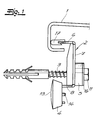
- the devices shown in the figures are called Designated wall anchors and are used for wall-side fastening a sanitary tub that U-shaped on the inside has angled tub edge 1.
- To the basics Structure of the wall anchor include a U-shaped clamp 2 a fastening screw 3 for fastening on the wall of the clamp 2 and damping elements 4, 5 for sound decoupling between the sanitary tub and an adjacent one Wall.
- the clamping bracket 2 has one in the tub edge 1 engaging upper leg 6, a web 7 and one lower leg 8 with a support on the wall side angularly shaped foot 9.
- the foot 9 of the clamp 7 rests on a first damping element 4.
- the Fastening screw 3 passes through a recess 10 of the Web 7, between the screw head 11 or one arranged on the screw shaft clamping nut 11 'and the web 7, a further damping element 5 is arranged.
- the block 4 is a rubber damping element designed and preferably consists of a vulcanized Synthetic rubber, e.g. B. an ethylene-propylene terpolymer (EPDM).
- EPDM ethylene-propylene terpolymer
- the block is also called Inscribed rubber block. It has a convexly curved wall Contact surface 13. This also applies to assembly-related Tilting movements of the wall anchor are always flat Installation on the wall guaranteed.
- the rubber block has 4 a recess 12 for a positive Engagement of the clamp bracket foot and is with a plug connection held on the foot 9 of the clamping bracket 2.
- the plug connection consists of a cone-shaped projection 14 of the rubber block 4 with Clamping action in a bore 15 of the foot element 9 intervenes.
- the damping element 5 resting on the web 7 is formed as an annular disc and exists in the embodiment also from a vulcanized synthetic rubber, z. B. an ethylene-propylene terpolymer (EPDM). to better pressure distribution is between the screw head 11 and the damping element 5, a washer 16 is arranged.
- EPDM ethylene-propylene terpolymer
- the recess 10 of the clamping bracket is designed as an elongated hole.
- the figures also show that the upper leg 6 of the clamp 2 an edge protection profile 17 is attached.
- FIGS. 4 and 5 are the damping elements 4, 5 and that on the Upper leg 6 of the clamp 2 arranged, also Edge protection profile 17 designed as an elastomer element firmly connected to the clamp 2.
- the foot 9 and the free leg 6 of the clamp 2 contain holes 25, which are filled with elastomer material.
- the Damping element 5 is formed with a collar 26, the the edge of the recess 10 includes.
- the recess 10 and the associated opening of the damping element 5 designed as elongated holes.
- the embodiment shown in Fig. 5 lends itself when the clamp 6 for the purpose the corrosion protection is galvanized.
- the clamp 2 with the fastening screw 3 on one Wall plate 18 held that as a lid with one to the wall angled edge and a recess 19 for the foot-side damping element 4 and formed by a Screw 20 is attachable to the wall.
- the foot side Damping element 4 is designed as a disc and in the Receiving recess 19 guided vertically adjustable. It has a body made of an elastic material, e.g. B. a mixed cell polyether urethane on one side on the side facing away from the clamping bracket with a Cover layer 21 laminated from a hard material. The hard top layer improves the pressure distribution in the elastic body.
- the clamping bracket 2 has a centering lug 22 which in a hole 23 of the foot-side damping element 4 engages.
- On the shaft is the fastening screw 3 holding the clamping bracket 2 a hose 24 slid onto a metallic one Prevents contact of the screw shaft with the clamping bracket 2.
- the foot-side damping element 4 and the damping element 5, which is between one on the screw shaft arranged clamping nut 11 'and the web 10 are identical. Both damping elements 4, 5 are designed as ring disks and have an elastic body and a one-sided lamination from a hard cover layer 21.
- On the top Leg 6 of the clamping bracket 2 is an edge protection profile 17 attached.
Landscapes
- Health & Medical Sciences (AREA)
- Public Health (AREA)
- Epidemiology (AREA)
- General Health & Medical Sciences (AREA)
- Building Environments (AREA)
- Joining Of Building Structures In Genera (AREA)
- Sink And Installation For Waste Water (AREA)
Priority Applications (3)
| Application Number | Priority Date | Filing Date | Title |
|---|---|---|---|
| AT00128751T ATE254875T1 (de) | 2000-12-30 | 2000-12-30 | Wandanker zur randseitigen befestigung einer sanitärwanne |
| DE50004587T DE50004587D1 (de) | 2000-12-30 | 2000-12-30 | Wandanker zur randseitigen Befestigung einer Sanitärwanne |
| EP00128751A EP1219218B1 (fr) | 2000-12-30 | 2000-12-30 | Ancrage mural pour fixer le bord d'une baignoire |
Applications Claiming Priority (1)
| Application Number | Priority Date | Filing Date | Title |
|---|---|---|---|
| EP00128751A EP1219218B1 (fr) | 2000-12-30 | 2000-12-30 | Ancrage mural pour fixer le bord d'une baignoire |
Publications (2)
| Publication Number | Publication Date |
|---|---|
| EP1219218A1 true EP1219218A1 (fr) | 2002-07-03 |
| EP1219218B1 EP1219218B1 (fr) | 2003-11-26 |
Family
ID=8170872
Family Applications (1)
| Application Number | Title | Priority Date | Filing Date |
|---|---|---|---|
| EP00128751A Expired - Lifetime EP1219218B1 (fr) | 2000-12-30 | 2000-12-30 | Ancrage mural pour fixer le bord d'une baignoire |
Country Status (3)
| Country | Link |
|---|---|
| EP (1) | EP1219218B1 (fr) |
| AT (1) | ATE254875T1 (fr) |
| DE (1) | DE50004587D1 (fr) |
Cited By (2)
| Publication number | Priority date | Publication date | Assignee | Title |
|---|---|---|---|---|
| CN104875815A (zh) * | 2015-05-06 | 2015-09-02 | 柳州杰龙汽车零部件制造有限公司 | 一种汽车减震系统的支撑装置 |
| RU2746893C1 (ru) * | 2020-11-05 | 2021-04-21 | Ринат Рашидович Мухамеджанов | Устройство крепления горизонтальных поверхностей к стене помещения |
Citations (5)
| Publication number | Priority date | Publication date | Assignee | Title |
|---|---|---|---|---|
| FR1399294A (fr) * | 1964-06-22 | 1965-05-14 | Fixation murale pour baignoire | |
| DE3736134C1 (en) * | 1987-10-26 | 1988-09-01 | Willi Pauli | Wall clamp for fixing and supporting a bathtub or shower trough |
| EP0635233A2 (fr) * | 1993-07-19 | 1995-01-25 | E. Missel GmbH & Co. | Dispositif pour la fixation avec découplage sonore de bords de baignoires et douches |
| DE19632710A1 (de) * | 1996-08-14 | 1998-02-19 | Altura Leiden Holding | Befestigungsvorrichtung |
| DE20012610U1 (de) | 2000-07-20 | 2000-10-05 | E. Missel GmbH & Co. KG, 70374 Stuttgart | Fixiervorrichtung |
-
2000
- 2000-12-30 EP EP00128751A patent/EP1219218B1/fr not_active Expired - Lifetime
- 2000-12-30 DE DE50004587T patent/DE50004587D1/de not_active Expired - Fee Related
- 2000-12-30 AT AT00128751T patent/ATE254875T1/de not_active IP Right Cessation
Patent Citations (5)
| Publication number | Priority date | Publication date | Assignee | Title |
|---|---|---|---|---|
| FR1399294A (fr) * | 1964-06-22 | 1965-05-14 | Fixation murale pour baignoire | |
| DE3736134C1 (en) * | 1987-10-26 | 1988-09-01 | Willi Pauli | Wall clamp for fixing and supporting a bathtub or shower trough |
| EP0635233A2 (fr) * | 1993-07-19 | 1995-01-25 | E. Missel GmbH & Co. | Dispositif pour la fixation avec découplage sonore de bords de baignoires et douches |
| DE19632710A1 (de) * | 1996-08-14 | 1998-02-19 | Altura Leiden Holding | Befestigungsvorrichtung |
| DE20012610U1 (de) | 2000-07-20 | 2000-10-05 | E. Missel GmbH & Co. KG, 70374 Stuttgart | Fixiervorrichtung |
Cited By (2)
| Publication number | Priority date | Publication date | Assignee | Title |
|---|---|---|---|---|
| CN104875815A (zh) * | 2015-05-06 | 2015-09-02 | 柳州杰龙汽车零部件制造有限公司 | 一种汽车减震系统的支撑装置 |
| RU2746893C1 (ru) * | 2020-11-05 | 2021-04-21 | Ринат Рашидович Мухамеджанов | Устройство крепления горизонтальных поверхностей к стене помещения |
Also Published As
| Publication number | Publication date |
|---|---|
| DE50004587D1 (de) | 2004-01-08 |
| EP1219218B1 (fr) | 2003-11-26 |
| ATE254875T1 (de) | 2003-12-15 |
Similar Documents
| Publication | Publication Date | Title |
|---|---|---|
| DE10119892C2 (de) | Deckel, insbesondere zur Dämpfung des Geräusches eines Verbrennungsmotors | |
| AT504913A4 (de) | Winkelverbinder | |
| DE3834329C2 (de) | Schienenlager | |
| DE3012899A1 (de) | Vibrationen daempfendes befestigungsglied | |
| DE10308906A1 (de) | Befestigungsclip, insbesondere zum Befestigen eines eine Fensterscheibe einfassenden Dichtungs- und/oder Führungsprofils an der Karosserie eines Kraftfahrzeugs | |
| EP0987368B1 (fr) | Fixation d'un contre-rail | |
| DE7820319U1 (de) | Vorrichtung zum befestigen eines einbauelements wie einer einbauspuele, einer herdmulde o.dgl. in eine platte | |
| DE10300723B4 (de) | Sammelschienensystem und Anschluss- oder Geräte-Adapter | |
| EP1219218B1 (fr) | Ancrage mural pour fixer le bord d'une baignoire | |
| DE102005024600B4 (de) | Befestigung einer Unterlageplatte | |
| DE102005052286B3 (de) | System zur Befestigung einer Platte | |
| EP1418282B1 (fr) | Dispositif de support pour le support d'une armature à un évier monté dans une plaque de travail | |
| DE1708640A1 (de) | Vorrichtung zur Befestigung einer Eisenbahnschiene an eine Stahl-,Beton- oder Holzschwelle und Verfahren zur Einstellung der Hoehe einer Eisenbahnschiene | |
| DE4032431C1 (en) | Vehicle exhaust suspension unit - incorporates block-shaped rubber holder with bores running parallel to its broad sides | |
| AT393075B (de) | Befestigungselement fuer waschbecken | |
| CH679228A5 (fr) | ||
| EP1508642A1 (fr) | Dispositif de fixation de rail | |
| DE4324754C2 (de) | Schalldämpfende Montagevorrichtung für die Installation von Sanitär-, Heizungs- und Lüftungsarmaturen und Versorgungsleitungen | |
| EP0635233B1 (fr) | Dispositif pour la fixation avec découplage sonore de bords de baignoires et douches | |
| EP1208783A1 (fr) | Ancrage mural pour l'accrochage au mur d'une cuve sanitaire | |
| DE1053016B (de) | Befestigung seitlich durch Rippen gehaltener Eisenbahnschienen mittels in die Rippen eingreifender federnder Spannbuegel | |
| EP0545123B1 (fr) | Aménagement de la fixation d'un rail | |
| EP1174066B1 (fr) | Dispositif de fixation | |
| EP1418281B1 (fr) | Dispositif de support pour le support d'une armature à un évier monté dans une plaque de travail | |
| EP1380757A1 (fr) | Element de construction avec un trou pour la fixation |
Legal Events
| Date | Code | Title | Description |
|---|---|---|---|
| PUAI | Public reference made under article 153(3) epc to a published international application that has entered the european phase |
Free format text: ORIGINAL CODE: 0009012 |
|
| 17P | Request for examination filed |
Effective date: 20010517 |
|
| AK | Designated contracting states |
Kind code of ref document: A1 Designated state(s): AT BE CH CY DE DK ES FI FR GB GR IE IT LI LU MC NL PT SE TR |
|
| AX | Request for extension of the european patent |
Free format text: AL;LT;LV;MK;RO;SI |
|
| AKX | Designation fees paid |
Designated state(s): AT CH DE LI |
|
| GRAH | Despatch of communication of intention to grant a patent |
Free format text: ORIGINAL CODE: EPIDOS IGRA |
|
| GRAS | Grant fee paid |
Free format text: ORIGINAL CODE: EPIDOSNIGR3 |
|
| GRAA | (expected) grant |
Free format text: ORIGINAL CODE: 0009210 |
|
| AK | Designated contracting states |
Kind code of ref document: B1 Designated state(s): AT CH DE LI |
|
| REG | Reference to a national code |
Ref country code: CH Ref legal event code: EP |
|
| PGFP | Annual fee paid to national office [announced via postgrant information from national office to epo] |
Ref country code: AT Payment date: 20031201 Year of fee payment: 4 |
|
| REF | Corresponds to: |
Ref document number: 50004587 Country of ref document: DE Date of ref document: 20040108 Kind code of ref document: P |
|
| REG | Reference to a national code |
Ref country code: IE Ref legal event code: FG4D Free format text: GERMAN |
|
| REG | Reference to a national code |
Ref country code: CH Ref legal event code: NV Representative=s name: KELLER & PARTNER PATENTANWAELTE AG |
|
| REG | Reference to a national code |
Ref country code: IE Ref legal event code: FD4D |
|
| PLBE | No opposition filed within time limit |
Free format text: ORIGINAL CODE: 0009261 |
|
| STAA | Information on the status of an ep patent application or granted ep patent |
Free format text: STATUS: NO OPPOSITION FILED WITHIN TIME LIMIT |
|
| 26N | No opposition filed |
Effective date: 20040827 |
|
| PGFP | Annual fee paid to national office [announced via postgrant information from national office to epo] |
Ref country code: DE Payment date: 20041214 Year of fee payment: 5 |
|
| PG25 | Lapsed in a contracting state [announced via postgrant information from national office to epo] |
Ref country code: AT Free format text: LAPSE BECAUSE OF NON-PAYMENT OF DUE FEES Effective date: 20041230 |
|
| PG25 | Lapsed in a contracting state [announced via postgrant information from national office to epo] |
Ref country code: LI Free format text: LAPSE BECAUSE OF NON-PAYMENT OF DUE FEES Effective date: 20041231 Ref country code: CH Free format text: LAPSE BECAUSE OF NON-PAYMENT OF DUE FEES Effective date: 20041231 |
|
| REG | Reference to a national code |
Ref country code: CH Ref legal event code: PL |
|
| PG25 | Lapsed in a contracting state [announced via postgrant information from national office to epo] |
Ref country code: DE Free format text: LAPSE BECAUSE OF NON-PAYMENT OF DUE FEES Effective date: 20060701 |