EP1219762A2 - Dispositif de sécurité pour la protection d'une personne travaillant sur un toit - Google Patents
Dispositif de sécurité pour la protection d'une personne travaillant sur un toit Download PDFInfo
- Publication number
- EP1219762A2 EP1219762A2 EP01120527A EP01120527A EP1219762A2 EP 1219762 A2 EP1219762 A2 EP 1219762A2 EP 01120527 A EP01120527 A EP 01120527A EP 01120527 A EP01120527 A EP 01120527A EP 1219762 A2 EP1219762 A2 EP 1219762A2
- Authority
- EP
- European Patent Office
- Prior art keywords
- roof
- mounting flange
- safety
- safety device
- bracket
- Prior art date
- Legal status (The legal status is an assumption and is not a legal conclusion. Google has not performed a legal analysis and makes no representation as to the accuracy of the status listed.)
- Pending
Links
- 238000000034 method Methods 0.000 claims abstract description 7
- 238000007789 sealing Methods 0.000 claims description 24
- 238000010079 rubber tapping Methods 0.000 claims description 5
- 238000009434 installation Methods 0.000 claims description 4
- 230000000087 stabilizing effect Effects 0.000 claims 1
- 239000000969 carrier Substances 0.000 description 3
- XEEYBQQBJWHFJM-UHFFFAOYSA-N Iron Chemical compound [Fe] XEEYBQQBJWHFJM-UHFFFAOYSA-N 0.000 description 2
- 229910000831 Steel Inorganic materials 0.000 description 2
- 230000001681 protective effect Effects 0.000 description 2
- 239000010959 steel Substances 0.000 description 2
- 230000000712 assembly Effects 0.000 description 1
- 238000000429 assembly Methods 0.000 description 1
- 230000001419 dependent effect Effects 0.000 description 1
- 230000000694 effects Effects 0.000 description 1
- 230000001771 impaired effect Effects 0.000 description 1
- 229910052742 iron Inorganic materials 0.000 description 1
- 239000000463 material Substances 0.000 description 1
- 239000000565 sealant Substances 0.000 description 1
- 239000003351 stiffener Substances 0.000 description 1
Images


Classifications
-
- A—HUMAN NECESSITIES
- A62—LIFE-SAVING; FIRE-FIGHTING
- A62B—DEVICES, APPARATUS OR METHODS FOR LIFE-SAVING
- A62B35/00—Safety belts or body harnesses; Similar equipment for limiting displacement of the human body, especially in case of sudden changes of motion
- A62B35/0043—Lifelines, lanyards, and anchors therefore
- A62B35/0068—Anchors
-
- E—FIXED CONSTRUCTIONS
- E04—BUILDING
- E04G—SCAFFOLDING; FORMS; SHUTTERING; BUILDING IMPLEMENTS OR AIDS, OR THEIR USE; HANDLING BUILDING MATERIALS ON THE SITE; REPAIRING, BREAKING-UP OR OTHER WORK ON EXISTING BUILDINGS
- E04G21/00—Preparing, conveying, or working-up building materials or building elements in situ; Other devices or measures for constructional work
- E04G21/32—Safety or protective measures for persons during the construction of buildings
- E04G21/3261—Safety-nets; Safety mattresses; Arrangements on buildings for connecting safety-lines
- E04G21/3276—Arrangements on buildings for connecting safety-lines
Definitions
- the invention relates to a security device for securing on roofs active persons and consists of at least one with a mounting flange connected safety bracket, the mounting flange on or in Support elements of a roof is attached.
- roofs As supporting elements for roofs are, for example, wooden beams, steel beams or Suitable for concrete ceilings.
- the mounting flanges of known safety devices are used for flat roofs, whereby when using concrete ceilings mostly the attachment is made by means of a screw-dowel connection.
- the invention is based on the technical problem, a safety device to create that for profiled or wavy roofs Can be used and also a method for assembling a surface such security device on the appropriate roofs available to deliver.
- a roof with a profiled or wavy surface shows alternating mostly parallel elevations and depressions.
- the roof altogether between that To arrange the mounting flange with the safety bracket and the support elements.
- This embodiment according to the invention has the decisive advantage that No opening is required through which the security bracket opens the roof penetrates. Accordingly, assembly is also considerably simplified, without sacrificing security for those working on the roof necessary security must be accepted.
- the arrangement of the Roof between the mounting flange of the safety bracket and the support elements allows an excellent sealing of the entire system in a simple manner.
- the mounting flange is as Fitting plate executed, which in cross-section looks like an approximation can have cup-shaped or U-shaped cross section.
- the edge areas, which are bent in the direction of the depressions of the roof the elevations of the roof should be as close as possible overtop. Thus, for example, rainwater over the wells of the Can be transported away without this in the screw connections of the Security device can penetrate.
- the screw connections are namely preferably at the elevations already mentioned of the roof.
- the safety bracket can be made from a flat profile or from a cylinder profile consist. If a flat profile is used as a safety bracket, stiffening elements should be provided to improve the support function become.
- the safety bracket shows regardless of its geometric cross-section each have a receiving opening through which, for example, safety ropes can be passed through or in which safety hooks can be used. Accordingly, the receiving opening on the safety bracket molded or attached safety eyelet.
- the roof should be in the sense the process features to be described below from several sandwich-like individual elements can be assembled, one above the other are layered or can be used in one another. This allows the assembly of the Simplify the roof considerably.
- a very advantageous and simple embodiment of an inventive Safety device is also seen in the fact that the support elements are carriers on which the mounting flange with self-tapping sealing screws is screwed on. These sealing screws penetrate the roof completely.
- Sealing screws are to be regarded as any type of screw that is secure Sealing against the ingress of moisture into the roof or respectively ensure the rooms below.
- Screws mentioned which are provided with a protective cap or one Have sealant in their upper threads or at which a sealing washer between the screw head and the surface which the screw head rests on.
- all types of carriers can be used as carriers come, for example T-beams, double-T beams, wooden beams or others Profile forms. There are almost no limits to the choice of material for the beams. The same is interpreted only depending on the one to be included Load.
- the support elements can form assemblies which either consist of a carrier and at least one purlin or of a carrier with an intermediate flange attached to each safety device.
- the mounting flange is screwed to its associated intermediate flange with self-tapping sealing screws.
- the sealing screws penetrate the roof completely.
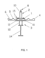
- FIG. 1 to 3 show a total of two safety devices according to the invention shown in sections and in cross section.
- These safety devices initially consist of a mounting flange 1.
- This is in the Cross section seen cup-shaped. Its rectangular in plan view Basic structure enables the support over two elevations 5 running in parallel of the roof equipped with elevations 5 and depressions 6 Elevations 5 and the depressions 6 are on the surface of the roof 4 arranged.
- the underside of the roof is flat here.
- the cross section seen cup-shaped design of the mounting flange 1 it has a shielding Function. Rainwater can therefore along the wells and to drain freely without the sealing function of the roof through the safety device according to the invention is impaired.
- a safety bracket is made in one piece was designated a total of 2.
- the safety bracket 2 has in its upper section facing away from the mounting flange 1 has a receiving opening 8 in Form of a safety eyelet. Through this receiving opening 8 can, for example a safety rope to guide the person to be secured haltem.
- a support element which has a total of 3 was designated below the roof 4 . In the simplest case, this support element can Carrier 14 be.
- FIGS. 1 to 3 an assembly was used as the supporting element 3 used, the present from a carrier 14, which here as a double-T carrier and an intermediate flange 12 fastened on this carrier 14 consists.
- the roof 4 is in a solution according to the invention between the Intermediate flange 12 and the mounting flange 1 arranged.
- the components of the safety device serve sealing screws 11, which from the top of the roof through the mounting flange 1 and the roof 4 through until the screw head on the mounting flange 1 rests.
- Stiffening elements 9 are present, which is the safety bracket designed as a flat profile 7 support.
- seals 15 are provided.
- This can consist of a glued on sealing tape, so that the assembly too here is not complicated by the application of the seal.
- the intermediate flanges 12 are only to be provided where a safety bracket is attached to the roof.
- 12 purlins 13 are provided spaced apart from the intermediate flanges. These bridge the distance between the underside of the roof 4 and the carrier 14 in a manner known per se.
- the carrier 14 is, for example, part of a supporting structure for a hall made of steel girders.
- a safety device according to the invention is particularly suitable for this application.
Landscapes
- Engineering & Computer Science (AREA)
- Architecture (AREA)
- Mechanical Engineering (AREA)
- Civil Engineering (AREA)
- Structural Engineering (AREA)
- Health & Medical Sciences (AREA)
- General Health & Medical Sciences (AREA)
- Business, Economics & Management (AREA)
- Emergency Management (AREA)
- Emergency Lowering Means (AREA)
- Roof Covering Using Slabs Or Stiff Sheets (AREA)
Applications Claiming Priority (2)
| Application Number | Priority Date | Filing Date | Title |
|---|---|---|---|
| DE10052572 | 2000-10-23 | ||
| DE10052572A DE10052572C2 (de) | 2000-10-23 | 2000-10-23 | Sicherheitsvorrichtung |
Publications (1)
| Publication Number | Publication Date |
|---|---|
| EP1219762A2 true EP1219762A2 (fr) | 2002-07-03 |
Family
ID=7660802
Family Applications (1)
| Application Number | Title | Priority Date | Filing Date |
|---|---|---|---|
| EP01120527A Pending EP1219762A2 (fr) | 2000-10-23 | 2001-08-29 | Dispositif de sécurité pour la protection d'une personne travaillant sur un toit |
Country Status (2)
| Country | Link |
|---|---|
| EP (1) | EP1219762A2 (fr) |
| DE (1) | DE10052572C2 (fr) |
Cited By (1)
| Publication number | Priority date | Publication date | Assignee | Title |
|---|---|---|---|---|
| EP2767652A2 (fr) | 2013-02-14 | 2014-08-20 | Torbau Schmidiger | Protection contre la chute sur des toitures |
Families Citing this family (2)
| Publication number | Priority date | Publication date | Assignee | Title |
|---|---|---|---|---|
| DE20216527U1 (de) | 2002-10-26 | 2003-01-02 | Vollack Stahltechnik GmbH & Co., 76189 Karlsruhe | Absturzsicherungsvorrichtung für ein Dach, insbesondere ein Flachdach |
| NL1032405C2 (nl) * | 2006-09-01 | 2008-03-04 | Cladding Partners B V | Werkwijze voor het vervaardigen van een dak van een gebouw en een dak voor een gebouw. |
Family Cites Families (1)
| Publication number | Priority date | Publication date | Assignee | Title |
|---|---|---|---|---|
| DD281847A5 (de) * | 1988-12-22 | 1990-08-22 | Kooperative Einrichtung Landba | Anordnung zur befestigung von fallschutzmitteln |
-
2000
- 2000-10-23 DE DE10052572A patent/DE10052572C2/de not_active Expired - Fee Related
-
2001
- 2001-08-29 EP EP01120527A patent/EP1219762A2/fr active Pending
Cited By (1)
| Publication number | Priority date | Publication date | Assignee | Title |
|---|---|---|---|---|
| EP2767652A2 (fr) | 2013-02-14 | 2014-08-20 | Torbau Schmidiger | Protection contre la chute sur des toitures |
Also Published As
| Publication number | Publication date |
|---|---|
| DE10052572A1 (de) | 2002-05-02 |
| DE10052572C2 (de) | 2002-11-28 |
Similar Documents
| Publication | Publication Date | Title |
|---|---|---|
| DE10052572C2 (de) | Sicherheitsvorrichtung | |
| EP4554087B1 (fr) | Support et agencement pour une sous-structure de modules photovoltaïques | |
| DE102015100700A1 (de) | Dachsicherungshalter | |
| DE102012105985A1 (de) | Vorrichtung zur Sicherung von Personen gegen Absturz | |
| EP0433236B1 (fr) | Construction de support pour couverture de toit | |
| DE102005027592A1 (de) | Vorrichtung zur Sicherung von auf Dächern, insbesondere Flachdächern, tätigen Personen | |
| WO1982004283A1 (fr) | Ancrage d'echelons en fer dans des elements en beton ou analogues | |
| EP1947260A2 (fr) | Agencement destiné au recouvrement, en particulier d'une sous-toiture | |
| EP0524631A1 (fr) | Dispositif pour monter des vitrages isolants | |
| DE102010001692A1 (de) | Haube zum Aufsetzen auf einen Betonpfosten | |
| DE202008008405U1 (de) | Verbindungsbeschlag | |
| AT402833B (de) | Vorrichtung zur befestigung von firstabdeckungen am dachfirst einer dacheindeckung | |
| DE3420841A1 (de) | Verbindungsvorrichtung zur erstellung einer mehrdimensionalen konstruktion | |
| DE102018114871A1 (de) | Installationsanordnung für eine Geschossdecke | |
| DE4313728C1 (de) | Schutzvorrichtung zur Vermeidung von Baustoffkorrosion | |
| DE202017103966U1 (de) | Halteklammer für eine Dachpfanne | |
| DE29809239U1 (de) | Fassade | |
| DE10324293B3 (de) | Befestigungseinrichtung für eine Absturzsicherung an Dachflächen | |
| DE102014003761B4 (de) | Befestigungsvorrichtung für Bleche von Metallfassaden und -dächern | |
| DE102005001216B4 (de) | Halteprofil | |
| DE102015205715A1 (de) | Befestigungsanordnung zur Personen- und/oder Sachensicherung an Dächern | |
| DE102016216212A1 (de) | Überdachungsvorrichtung und Verfahren zur Herstellung einer Überdachungsvorrichtung | |
| DE202004007940U1 (de) | Halterung für einen Blumenkasten | |
| EP4435344A1 (fr) | Système de fixation | |
| DE29507185U1 (de) | Durchführungseinrichtung für eine flexible Bahn, insbesondere Dach-Unterspannbahn |
Legal Events
| Date | Code | Title | Description |
|---|---|---|---|
| PUAI | Public reference made under article 153(3) epc to a published international application that has entered the european phase |
Free format text: ORIGINAL CODE: 0009012 |
|
| AK | Designated contracting states |
Kind code of ref document: A2 Designated state(s): AT BE CH CY DE DK ES FI FR GB GR IE IT LI LU MC NL PT SE TR |
|
| AX | Request for extension of the european patent |
Free format text: AL;LT;LV;MK;RO;SI |
|
| 18W | Application withdrawn |
Effective date: 20040117 |
|
| D18W | Application withdrawn (deleted) | ||
| STAA | Information on the status of an ep patent application or granted ep patent |
Free format text: STATUS: THE APPLICATION IS DEEMED TO BE WITHDRAWN |
|
| 18D | Application deemed to be withdrawn |
Effective date: 20040302 |