EP1219780A2 - Refroidissement d'un élément d'une turbomachine par jet - Google Patents
Refroidissement d'un élément d'une turbomachine par jet Download PDFInfo
- Publication number
- EP1219780A2 EP1219780A2 EP01129066A EP01129066A EP1219780A2 EP 1219780 A2 EP1219780 A2 EP 1219780A2 EP 01129066 A EP01129066 A EP 01129066A EP 01129066 A EP01129066 A EP 01129066A EP 1219780 A2 EP1219780 A2 EP 1219780A2
- Authority
- EP
- European Patent Office
- Prior art keywords
- turbine blade
- cooled
- flow
- cooling
- wall section
- Prior art date
- Legal status (The legal status is an assumption and is not a legal conclusion. Google has not performed a legal analysis and makes no representation as to the accuracy of the status listed.)
- Granted
Links
Images


Classifications
-
- F—MECHANICAL ENGINEERING; LIGHTING; HEATING; WEAPONS; BLASTING
- F01—MACHINES OR ENGINES IN GENERAL; ENGINE PLANTS IN GENERAL; STEAM ENGINES
- F01D—NON-POSITIVE DISPLACEMENT MACHINES OR ENGINES, e.g. STEAM TURBINES
- F01D5/00—Blades; Blade-carrying members; Heating, heat-insulating, cooling or antivibration means on the blades or the members
- F01D5/12—Blades
- F01D5/14—Form or construction
- F01D5/18—Hollow blades, i.e. blades with cooling or heating channels or cavities; Heating, heat-insulating or cooling means on blades
- F01D5/187—Convection cooling
-
- F—MECHANICAL ENGINEERING; LIGHTING; HEATING; WEAPONS; BLASTING
- F05—INDEXING SCHEMES RELATING TO ENGINES OR PUMPS IN VARIOUS SUBCLASSES OF CLASSES F01-F04
- F05D—INDEXING SCHEME FOR ASPECTS RELATING TO NON-POSITIVE-DISPLACEMENT MACHINES OR ENGINES, GAS-TURBINES OR JET-PROPULSION PLANTS
- F05D2260/00—Function
- F05D2260/20—Heat transfer, e.g. cooling
- F05D2260/201—Heat transfer, e.g. cooling by impingement of a fluid
Definitions
- the invention relates to a device for impingement cooling in one Fluid machine of heat-exposed component with a component to be cooled Wall section, the at least one side at least one impact cooling air flow exposed through a flow channel within a surface element, which is arranged at a distance from the wall section to be cooled, passes through and strikes the wall section to be cooled. Further relates the invention to a related cooling method and a method for Production of a heat-resistant component.
- Cooling measures have been taken to precisely expose those to the hot gases Cool components, which reduces the thermal load as well as the Component life is to be increased.
- those components that are supplied with cooling air are targeted Side of the compressor branched off in partial flows and by accordingly provided cooling channels is fed directly to the components to be cooled.
- the maximum of the so-called external Heat transfer coefficients are typically at those points of the Turbine blade leading edge reached, on which the hot gases meet vertically and thus lead to a maximum accumulation effect on the front edge of the turbine blade. It is precisely these areas that need to be cooled with maximum efficiency in order to ensure that not to exceed material-related temperature limits.
- a preferred technique for cooling the turbine blade leading edge is based on the targeted supply of cooling air within the turbine blade along in itself Inside the blade cooling channels, the cooling air directly on the The inside of the turbine blade leading edge is passed around the front edge to cool in a convective manner.
- a turbine blade designed in this way is known, for example, from US Pat. No. 5,603,606 can be seen in the cross section through the Front region of a turbine blade is shown, the cooling air duct 166th having a connecting gap 180 with a front cooling volume 168 is connected, which is directly inside the turbine blade on the Turbine blade leading edge adjoins.
- the connection channel 180 is on one side of the turbine blade inner wall is limited, which means that in the front Volume of cooling air introduced tangentially the inside of the Turbine blade leading edge overflows. This will make the entire area the turbine blade leading edge is subjected to an internal cooling air flow, however this can just the hot areas described above along the Insufficient cooling of the turbine blade leading edge.
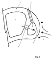
- FIG Area of a turbine blade 1 shown a cross section through the front is in FIG Area of a turbine blade 1 shown.
- FIG Area of a turbine blade 1 shown schematically streamlines 2, which on the Turbine blade leading edge 3 should represent hot gases.
- the turbine blade 1 provides an inner cooling duct 4, which passes through at least one connecting channel 5, which is located in a partition 8, with a front volume 6 is connected, in the same one with the Extending outlet duct 7 connected to the turbine blade top.
- Cooling air which is supplied at high pressure via the cooling channel 4, passes through the Flow channel 5 in the volume 6 at high speed and hits the Area 3 of the turbine blade leading edge.
- This is also known as impingement cooling
- cooling technology can reinforces that area on the turbine blade leading edge that is cooled by the Hot gases are most thermally stressed. Closer examination of the known impingement air flow through the connecting channel in the direction of cooling turbine blade leading edge, however, show that the rectilinear flow channel only an expansion of the cooling jet when Allows leaving the connection channel. This will only cover small areas effectively applied cooling air to the inside of the turbine blade leading edge and the cooling effect is limited to a very restricted area.
- Another disadvantage of the straight-line connecting channels is that that the emerging cooling jet massively cools a very small area and therefore too strong temperature gradients and caused by it Stress gradient in the material contributes.
- the invention has for its object a device for impingement cooling in a turbomachine exposed to heat, preferably one Turbine blade, according to the type mentioned above evolve that area of heat-stressed Turbine blade leading edge can be cooled as effectively and optimally as possible that the pursuit of higher combustion chamber temperatures or a reduction the cooling air requirement used can be taken into account accordingly.
- claim 12 The object underlying the invention is achieved in claim 1 specified.
- the subject of claim 12 is an inventive method for Impingement cooling.
- Claim 14 relates to a manufacturing method according to the invention Component according to claim 1.
- Advantageously further developing the inventive concept Features are the subject of the subclaims and the entire description, in particular with reference to the exemplary embodiments according to drawings, refer to.
- the device for impingement cooling is one in one Fluid machine of heat-exposed component with a component to be cooled Wall section, the at least one side at least one impact air cooling flow is exposed through a flow channel within a surface element is spaced from the wall section to be cooled, passes through and on strikes the wall section to be cooled, designed such that the Flow channel has an inlet and an outlet opening that the Outlet opening directly faces the wall section to be cooled and that the inlet opening has a flow cross-section that is smaller than that Flow cross section of the outlet opening is.
- FIG. 1 shows the front area of a turbine blade 1 in Cross-sectional view with a main cooling channel 4, which via a flow channel 5 is connected to a front cooling volume 6, the rest of a Partition 8 is separated from the main cooling duct 4.
- the front cooling volume 6 has an outlet channel 7, which opens on the surface of the turbine blade 1.
- the Cooling air supplied through the main cooling duct 4 passes through the at high pressure Flow channel 5 through and meets the flow channel 5 opposite lying inner wall of the turbine blade 1 in the area of Turbine blade leading edge 3.
- the flow channel 5 is included a flow cross section widening in the flow direction, so that in the form of an impact air cooling flow through the flow channel 5 cooling air passing therethrough emerges divergent from the flow channel 5 and thus applied to a larger area of the turbine blade leading edge 3.
- FIG. 2 shows a detailed representation of the geometric design of the Flow channel 5, which is provided within the partition 8, the Main cooling duct 4 separates from the front volume 6.
- the flow channel 5 has an inlet opening 9 and an outlet opening 10, the inlet opening 9 has a smaller cross section or smaller opening diameter than that Outlet opening 10.
- the flow channel 5 flared and has straight cut Boundary walls. In principle, however, it is also possible to have a funnel shape to provide curved boundary wall contours. It is essential that the Baffle air cooling flow in the longitudinal direction propagating through the flow channel 5 Flow profile widens divergent after passing through the flow channel in this way the largest possible area of the turbine blade leading edge 3 to be acted upon by impingement air cooling.
- the opening angle ⁇ shown in FIG. 2 is between the Center axis through the flow channel 5 and from a boundary wall included, values between 2 ° and 9 °.
- Typical mean diameters for the flow channel 5 are in the range between 0.5 and 7 mm.
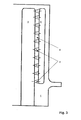
- FIG. 3 shows a longitudinal section through the front area of a turbine blade 1 shown, with the main cooling channel 4, the front volume 6 and the Partition 8, in the radial to the turbine blade 1 distributed a large number of individual Flow channels 5 is provided. All individual flow channels 5 are of this type oriented relative to the turbine blade leading edge 3, so that the through the Individual impingement cooling streams passing through flow channels immediately Able to cool the inner wall of the turbine blade leading edge.
- the conventional casting process which involves training within a mold of the flow channels designed according to the invention are heat-resistant Insert forms are provided which are subsequently removed from the casting, to expose the free flow channels.
Landscapes
- Engineering & Computer Science (AREA)
- Mechanical Engineering (AREA)
- General Engineering & Computer Science (AREA)
- Turbine Rotor Nozzle Sealing (AREA)
Applications Claiming Priority (2)
| Application Number | Priority Date | Filing Date | Title |
|---|---|---|---|
| DE10064271A DE10064271A1 (de) | 2000-12-22 | 2000-12-22 | Vorrichtung zur Prallkühlung eines in einer Strömungskraftmaschine hitzeexponierten Bauteils sowie Verfahren hierzu |
| DE10064271 | 2000-12-22 |
Publications (3)
| Publication Number | Publication Date |
|---|---|
| EP1219780A2 true EP1219780A2 (fr) | 2002-07-03 |
| EP1219780A3 EP1219780A3 (fr) | 2004-08-11 |
| EP1219780B1 EP1219780B1 (fr) | 2006-11-02 |
Family
ID=7668444
Family Applications (1)
| Application Number | Title | Priority Date | Filing Date |
|---|---|---|---|
| EP01129066A Expired - Lifetime EP1219780B1 (fr) | 2000-12-22 | 2001-12-07 | Dispositif et procédé de refroidissement d'un élément d'une turbomachine par jet |
Country Status (3)
| Country | Link |
|---|---|
| US (1) | US6634859B2 (fr) |
| EP (1) | EP1219780B1 (fr) |
| DE (2) | DE10064271A1 (fr) |
Cited By (1)
| Publication number | Priority date | Publication date | Assignee | Title |
|---|---|---|---|---|
| EP2196625A1 (fr) * | 2008-12-10 | 2010-06-16 | Siemens Aktiengesellschaft | Aube de turbine dotée d'un passage agencé dans une paroi de séparation et noyau de coulage associé |
Families Citing this family (14)
| Publication number | Priority date | Publication date | Assignee | Title |
|---|---|---|---|---|
| GB2402715B (en) * | 2003-06-10 | 2006-06-14 | Rolls Royce Plc | Gas turbine aerofoil |
| US7708525B2 (en) * | 2005-02-17 | 2010-05-04 | United Technologies Corporation | Industrial gas turbine blade assembly |
| US7520725B1 (en) | 2006-08-11 | 2009-04-21 | Florida Turbine Technologies, Inc. | Turbine airfoil with near-wall leading edge multi-holes cooling |
| US20090255268A1 (en) * | 2008-04-11 | 2009-10-15 | General Electric Company | Divergent cooling thimbles for combustor liners and related method |
| GB0811391D0 (en) * | 2008-06-23 | 2008-07-30 | Rolls Royce Plc | A rotor blade |
| US9296039B2 (en) | 2012-04-24 | 2016-03-29 | United Technologies Corporation | Gas turbine engine airfoil impingement cooling |
| DE102012016493A1 (de) * | 2012-08-21 | 2014-02-27 | Rolls-Royce Deutschland Ltd & Co Kg | Gasturbinenbrennkammer mit prallgekühlten Bolzen der Brennkammerschindeln |
| US9394798B2 (en) * | 2013-04-02 | 2016-07-19 | Honeywell International Inc. | Gas turbine engines with turbine airfoil cooling |
| US10309228B2 (en) * | 2016-06-09 | 2019-06-04 | General Electric Company | Impingement insert for a gas turbine engine |
| KR102028804B1 (ko) * | 2017-10-19 | 2019-10-04 | 두산중공업 주식회사 | 가스 터빈 디스크 |
| US20190277501A1 (en) * | 2018-03-07 | 2019-09-12 | United Technologies Corporation | Slot arrangements for an impingement floatwall film cooling of a turbine engine |
| US11391161B2 (en) | 2018-07-19 | 2022-07-19 | General Electric Company | Component for a turbine engine with a cooling hole |
| US11998974B2 (en) | 2022-08-30 | 2024-06-04 | General Electric Company | Casting core for a cast engine component |
| GB2639585A (en) * | 2024-03-18 | 2025-10-01 | Siemens Energy Global Gmbh & Co Kg | A wall section of a hot gas path part for a gas turbine and a method of additive manufacturing of a wall section |
Citations (1)
| Publication number | Priority date | Publication date | Assignee | Title |
|---|---|---|---|---|
| US5603606A (en) | 1994-11-14 | 1997-02-18 | Solar Turbines Incorporated | Turbine cooling system |
Family Cites Families (15)
| Publication number | Priority date | Publication date | Assignee | Title |
|---|---|---|---|---|
| IT963220B (it) * | 1971-11-01 | 1974-01-10 | Gen Electric | Paletta a bordo d entrata smussato per la riduzione del rumore parti colarmente per reattori a turboven tilatore |
| US3844343A (en) * | 1973-02-02 | 1974-10-29 | Gen Electric | Impingement-convective cooling system |
| US4775296A (en) | 1981-12-28 | 1988-10-04 | United Technologies Corporation | Coolable airfoil for a rotary machine |
| US4770608A (en) * | 1985-12-23 | 1988-09-13 | United Technologies Corporation | Film cooled vanes and turbines |
| US4738587A (en) * | 1986-12-22 | 1988-04-19 | United Technologies Corporation | Cooled highly twisted airfoil for a gas turbine engine |
| US5720431A (en) * | 1988-08-24 | 1998-02-24 | United Technologies Corporation | Cooled blades for a gas turbine engine |
| US5690473A (en) * | 1992-08-25 | 1997-11-25 | General Electric Company | Turbine blade having transpiration strip cooling and method of manufacture |
| US5403159A (en) * | 1992-11-30 | 1995-04-04 | United Technoligies Corporation | Coolable airfoil structure |
| US5271715A (en) * | 1992-12-21 | 1993-12-21 | United Technologies Corporation | Cooled turbine blade |
| JP3110227B2 (ja) * | 1993-11-22 | 2000-11-20 | 株式会社東芝 | タービン冷却翼 |
| US5688104A (en) * | 1993-11-24 | 1997-11-18 | United Technologies Corporation | Airfoil having expanded wall portions to accommodate film cooling holes |
| US5931638A (en) * | 1997-08-07 | 1999-08-03 | United Technologies Corporation | Turbomachinery airfoil with optimized heat transfer |
| US5967575A (en) * | 1998-05-18 | 1999-10-19 | Blake; Albert C. | Device for grabbing a hook supported by an object |
| GB2343486B (en) * | 1998-06-19 | 2000-09-20 | Rolls Royce Plc | Improvemnts in or relating to cooling systems for gas turbine engine airfoil |
| DE19921644B4 (de) * | 1999-05-10 | 2012-01-05 | Alstom | Kühlbare Schaufel für eine Gasturbine |
-
2000
- 2000-12-22 DE DE10064271A patent/DE10064271A1/de not_active Withdrawn
-
2001
- 2001-12-07 DE DE50111357T patent/DE50111357D1/de not_active Expired - Lifetime
- 2001-12-07 EP EP01129066A patent/EP1219780B1/fr not_active Expired - Lifetime
- 2001-12-10 US US10/006,725 patent/US6634859B2/en not_active Expired - Lifetime
Patent Citations (1)
| Publication number | Priority date | Publication date | Assignee | Title |
|---|---|---|---|---|
| US5603606A (en) | 1994-11-14 | 1997-02-18 | Solar Turbines Incorporated | Turbine cooling system |
Cited By (1)
| Publication number | Priority date | Publication date | Assignee | Title |
|---|---|---|---|---|
| EP2196625A1 (fr) * | 2008-12-10 | 2010-06-16 | Siemens Aktiengesellschaft | Aube de turbine dotée d'un passage agencé dans une paroi de séparation et noyau de coulage associé |
Also Published As
| Publication number | Publication date |
|---|---|
| EP1219780B1 (fr) | 2006-11-02 |
| US6634859B2 (en) | 2003-10-21 |
| DE50111357D1 (de) | 2006-12-14 |
| DE10064271A1 (de) | 2002-07-04 |
| EP1219780A3 (fr) | 2004-08-11 |
| US20020168264A1 (en) | 2002-11-14 |
Similar Documents
| Publication | Publication Date | Title |
|---|---|---|
| DE102007007177B4 (de) | Verfahren und Vorrichtung zum Kühlen von Gasturbinen- Rotorschaufeln | |
| EP1219780A2 (fr) | Refroidissement d'un élément d'une turbomachine par jet | |
| EP1320661B1 (fr) | Aube de turbine a gaz | |
| DE69932688T2 (de) | Kühlungsöffnungen für Gasturbinenkomponenten | |
| DE60317920T2 (de) | Effusionsgekühlter übergangskanal mit geformten kühllöchern | |
| DE69910913T2 (de) | Kühlbare Schaufel für Gasturbinen | |
| EP3183497B1 (fr) | Élément formant bouclier thermique et procédé de fabrication de celui-ci | |
| EP1219781A2 (fr) | Dispositif et méthode de refroidissement d'une plate-forme d'une aube de turbine | |
| DE60017396T2 (de) | Vorrichtung zur reduzierung der kühlung für einen turbineneinlasskanal | |
| DE1946535B2 (de) | Bauteil für ein Gasturbinentriebwerk | |
| DE102011055375A1 (de) | Turbomaschinenleitschaufel und Verfahren zur Kühlung einer Turbomaschinenleitschaufel | |
| EP1512489B1 (fr) | Aube pour turbine | |
| EP0232782A1 (fr) | Méthode et dispositif de refroidissement des aubes de turbines thermiques | |
| DE3711024A1 (de) | Gekuehlte schaufel fuer ein gasturbinentriebwerk | |
| DE102009040758A1 (de) | Umlenkvorrichtung für einen Leckagestrom in einer Gasturbine und Gasturbine | |
| EP2084368B1 (fr) | Aube de turbine | |
| DE102007061564A1 (de) | Schaufelblatt mit verbesserter Kühlschlitzanordnung | |
| EP1505254A2 (fr) | Turbine à gaz et méthode pour la refroidir | |
| DE102011053702A1 (de) | Turbinenschaufelblatt und Verfahren zur Kühlung eines Turbinenschaufelblattes | |
| WO2005019621A1 (fr) | Diffuseur place entre le compresseur et la chambre de combustion d'une turbine a gaz | |
| DE60117494T2 (de) | Kühlsystem für Gasturbinen-Statordüsen | |
| EP1456505A1 (fr) | Piece a sollicitation thermique | |
| DE102018108729B4 (de) | Strömungsführende Komponente mit einer Strömungsleitfläche sowie eine Gasturbinenschaufel | |
| CH706962B1 (de) | Serpentinenkühlung der Leitschaufelendwand. | |
| EP0954680B1 (fr) | Aube de turbine et son utilisation dans un systeme de turbine a gaz |
Legal Events
| Date | Code | Title | Description |
|---|---|---|---|
| PUAI | Public reference made under article 153(3) epc to a published international application that has entered the european phase |
Free format text: ORIGINAL CODE: 0009012 |
|
| AK | Designated contracting states |
Kind code of ref document: A2 Designated state(s): AT BE CH CY DE DK ES FI FR GB GR IE IT LI LU MC NL PT SE TR |
|
| AX | Request for extension of the european patent |
Free format text: AL;LT;LV;MK;RO;SI |
|
| RAP1 | Party data changed (applicant data changed or rights of an application transferred) |
Owner name: ALSTOM (SWITZERLAND) LTD |
|
| RAP1 | Party data changed (applicant data changed or rights of an application transferred) |
Owner name: ALSTOM TECHNOLOGY LTD |
|
| RIC1 | Information provided on ipc code assigned before grant |
Ipc: 7F 01D 25/12 A Ipc: 7F 01D 5/18 B |
|
| PUAL | Search report despatched |
Free format text: ORIGINAL CODE: 0009013 |
|
| AK | Designated contracting states |
Kind code of ref document: A3 Designated state(s): AT BE CH CY DE DK ES FI FR GB GR IE IT LI LU MC NL PT SE TR |
|
| AX | Request for extension of the european patent |
Extension state: AL LT LV MK RO SI |
|
| 17P | Request for examination filed |
Effective date: 20050114 |
|
| AKX | Designation fees paid |
Designated state(s): DE GB |
|
| RBV | Designated contracting states (corrected) |
Designated state(s): DE GB |
|
| GRAP | Despatch of communication of intention to grant a patent |
Free format text: ORIGINAL CODE: EPIDOSNIGR1 |
|
| RTI1 | Title (correction) |
Free format text: APPARATUS AND METHOD FOR THE IMPINGEMENT COOLING OF A TURBOMACHINE COMPONENT |
|
| GRAS | Grant fee paid |
Free format text: ORIGINAL CODE: EPIDOSNIGR3 |
|
| GRAA | (expected) grant |
Free format text: ORIGINAL CODE: 0009210 |
|
| AK | Designated contracting states |
Kind code of ref document: B1 Designated state(s): DE GB |
|
| REG | Reference to a national code |
Ref country code: GB Ref legal event code: FG4D Free format text: NOT ENGLISH |
|
| REF | Corresponds to: |
Ref document number: 50111357 Country of ref document: DE Date of ref document: 20061214 Kind code of ref document: P |
|
| GBT | Gb: translation of ep patent filed (gb section 77(6)(a)/1977) |
Effective date: 20061129 |
|
| PLBE | No opposition filed within time limit |
Free format text: ORIGINAL CODE: 0009261 |
|
| STAA | Information on the status of an ep patent application or granted ep patent |
Free format text: STATUS: NO OPPOSITION FILED WITHIN TIME LIMIT |
|
| 26N | No opposition filed |
Effective date: 20070803 |
|
| REG | Reference to a national code |
Ref country code: DE Ref legal event code: R082 Ref document number: 50111357 Country of ref document: DE Representative=s name: ROESLER, UWE, DIPL.-PHYS.UNIV., DE Ref country code: DE Ref legal event code: R081 Ref document number: 50111357 Country of ref document: DE Owner name: GENERAL ELECTRIC TECHNOLOGY GMBH, CH Free format text: FORMER OWNER: ALSTOM TECHNOLOGY LTD., BADEN, CH Ref country code: DE Ref legal event code: R081 Ref document number: 50111357 Country of ref document: DE Owner name: ANSALDO ENERGIA IP UK LIMITED, GB Free format text: FORMER OWNER: ALSTOM TECHNOLOGY LTD., BADEN, CH |
|
| PGFP | Annual fee paid to national office [announced via postgrant information from national office to epo] |
Ref country code: GB Payment date: 20161222 Year of fee payment: 16 Ref country code: DE Payment date: 20161213 Year of fee payment: 16 |
|
| REG | Reference to a national code |
Ref country code: DE Ref legal event code: R082 Ref document number: 50111357 Country of ref document: DE Representative=s name: ROESLER, UWE, DIPL.-PHYS.UNIV., DE Ref country code: DE Ref legal event code: R081 Ref document number: 50111357 Country of ref document: DE Owner name: ANSALDO ENERGIA IP UK LIMITED, GB Free format text: FORMER OWNER: GENERAL ELECTRIC TECHNOLOGY GMBH, BADEN, CH |
|
| REG | Reference to a national code |
Ref country code: GB Ref legal event code: 732E Free format text: REGISTERED BETWEEN 20170824 AND 20170830 |
|
| REG | Reference to a national code |
Ref country code: DE Ref legal event code: R119 Ref document number: 50111357 Country of ref document: DE |
|
| GBPC | Gb: european patent ceased through non-payment of renewal fee |
Effective date: 20171207 |
|
| PG25 | Lapsed in a contracting state [announced via postgrant information from national office to epo] |
Ref country code: DE Free format text: LAPSE BECAUSE OF NON-PAYMENT OF DUE FEES Effective date: 20180703 |
|
| PG25 | Lapsed in a contracting state [announced via postgrant information from national office to epo] |
Ref country code: GB Free format text: LAPSE BECAUSE OF NON-PAYMENT OF DUE FEES Effective date: 20171207 |