EP1219789A2 - Système et méthode pour refroidir le carter d'une turbomachine - Google Patents
Système et méthode pour refroidir le carter d'une turbomachine Download PDFInfo
- Publication number
- EP1219789A2 EP1219789A2 EP01128868A EP01128868A EP1219789A2 EP 1219789 A2 EP1219789 A2 EP 1219789A2 EP 01128868 A EP01128868 A EP 01128868A EP 01128868 A EP01128868 A EP 01128868A EP 1219789 A2 EP1219789 A2 EP 1219789A2
- Authority
- EP
- European Patent Office
- Prior art keywords
- supply air
- air
- blocking member
- cooling system
- housing
- Prior art date
- Legal status (The legal status is an assumption and is not a legal conclusion. Google has not performed a legal analysis and makes no representation as to the accuracy of the status listed.)
- Granted
Links
Images
Classifications
-
- F—MECHANICAL ENGINEERING; LIGHTING; HEATING; WEAPONS; BLASTING
- F01—MACHINES OR ENGINES IN GENERAL; ENGINE PLANTS IN GENERAL; STEAM ENGINES
- F01D—NON-POSITIVE DISPLACEMENT MACHINES OR ENGINES, e.g. STEAM TURBINES
- F01D25/00—Component parts, details, or accessories, not provided for in, or of interest apart from, other groups
- F01D25/08—Cooling; Heating; Heat-insulation
- F01D25/12—Cooling
-
- F—MECHANICAL ENGINEERING; LIGHTING; HEATING; WEAPONS; BLASTING
- F02—COMBUSTION ENGINES; HOT-GAS OR COMBUSTION-PRODUCT ENGINE PLANTS
- F02C—GAS-TURBINE PLANTS; AIR INTAKES FOR JET-PROPULSION PLANTS; CONTROLLING FUEL SUPPLY IN AIR-BREATHING JET-PROPULSION PLANTS
- F02C7/00—Features, components parts, details or accessories, not provided for in, or of interest apart form groups F02C1/00 - F02C6/00; Air intakes for jet-propulsion plants
- F02C7/12—Cooling of plants
- F02C7/16—Cooling of plants characterised by cooling medium
- F02C7/18—Cooling of plants characterised by cooling medium the medium being gaseous, e.g. air
- F02C7/185—Cooling means for reducing the temperature of the cooling air or gas
Definitions
- the invention relates to a cooling system and a method for cooling thermally claimed housing or housing parts in turbomachines, in particular in a turbine with the features of the preamble of claim 1 or claim 9.
- a conventional cooling system has an air supply line that connects a supply air connection of the housing to an environment of the housing, to supply air to the housing through the supply air line. Furthermore an exhaust air line is provided which is connected to an exhaust air connection of the housing is connected to remove the heated exhaust air through the housing.
- a blower is arranged in the supply air line, which drives the cooling air flow. In order to influence the cooling performance of such a cooling system, it is known the speed of the fan, e.g.
- Cooling air quantity supplied i.e. the supply air quantity is adjusted to thereby reduce the To change the cooling capacity of the cooling system.
- the invention seeks to remedy this.
- the present invention deals with deal with the problem for a cooling system or for a method of the beginning mentioned type to specify an embodiment, the adjustment of the cooling capacity in a relatively large area.
- the invention is based on the general idea that the cooling capacity over the Change the temperature of the incoming air. Since the flow conditions basically remain unchanged when flowing through the housing can, the cooling capacity of the cooling system by changing the supply air temperature can be adjusted in a very large range. Furthermore, by increasing the supply air temperature along the flow path temperature gradient forming in the housing can be reduced, as a result of which undesirable Tensions in the housing can be reduced or avoided.
- the means provided for changing the supply air temperature can, for example a corresponding heating device and / or cooling device, which are arranged in the supply air line upstream or downstream of the fan can.
- a cooling and / or heating device can also be placed in the fan be integrated.
- an embodiment is preferred in which the means for changing of the supply air temperature have a recirculation line which is the supply air line connects upstream of the blower with the exhaust air line, in this air recirculation line an adjustable circulating air blocking element is arranged.
- the supply air temperature by adding more or less Exhaust air to supply air changed. The more exhaust air is added to the supply air, the more the supply air temperature is higher.
- a decisive advantage of this embodiment can be seen in the fact that there is no additional to increase the supply air temperature Energy is required because the required heat is extracted from the exhaust air. About that In addition, such an embodiment is comparatively inexpensive to implement.
- the blower can be designed that the amount of air delivered by the blower is adjustable.
- the on known measure to change the cooling capacity with the equivalent Combined measure according to the invention whereby additional Adjustment options result.
- an adjustable exhaust air blocking element can be arranged.
- an adjustable one can be located in the supply air line upstream of the recirculating air line Supply air blocking element can be arranged.
- the problem underlying the invention is also solved by a method solved the features of claim 9.
- the invention is based on the general idea of influencing the cooling capacity via the supply air temperature.
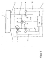
- FIG. 1 shows a schematic basic illustration of an inventive one Cooling system.
- a housing or housing part 1 is otherwise not shown Fluid machine, e.g. a turbine, represented in simplified form by a rectangle.
- This housing 1 is intended with the aid of a cooling system 2 according to the invention be cooled.
- the cooling system 2 comprises a supply air line 3, which is connected to a supply air connection 4 of the housing 1.
- a flow path not shown here, the input side with the supply air connection 4 and on the output side with an exhaust air connection 5 of the housing 1 communicates.
- Exhaust air line 6 of the cooling system 2 is one Exhaust air line 6 of the cooling system 2 connected.
- a blower 7 is arranged, the drive motor 8 via a control line 9 can be actuated by a control device 10 of the cooling system 2 is.
- the blower is 7 adjustable in terms of its delivery rate. For example, the fan 7 delivered air volume adjusted via the speed of the drive motor 8 become.
- the cooling system 2 has a circulating air line 11 with which the supply air line 3 is connected upstream of the blower 7 with the exhaust air line 6.
- a recirculating air blocking element 12 which is arranged with the help of an associated Actuator 13 is adjustable.
- the actuator 13 is actuated again via a corresponding control line 14, which is connected to the control device 10 is connected.
- the opening cross section can be set via the actuator 13 of the circulating air blocking member 12 between a completely blocked Locked position and a fully open open position adjusted be at least one intermediate position is adjustable.
- Supply air blocking member 15 upstream of the circulating air line 11 arranged, which is adjustable via an associated actuator 16, the one Control line 17 can also be actuated by the control device 10. That too Supply air blocking member 15 is preferably between a fully open open position and a fully closed closed position, whereby at least one intermediate position is also adjustable here.
- An exhaust air blocking element 18 is located in the exhaust air line 6 downstream of the recirculating air line 11 arranged with the help of an associated actuator 19 between a completely closed closed position and a fully open open position is adjustable, preferably at least one intermediate position is adjustable.
- the actuator 19 is also via a control line 20 can be actuated by the control device 10.
- the cooling of the housing 1 is carried out with the aid of the cooling system according to the invention 2 carried out as follows:
- the control device 10 enables an operating mode A in which the circulating air blocking member 12 is closed and in which the supply air blocking member 15 and that
- Exhaust air blocking member 18 are open.
- the invention works Cooling system 2 thus like a conventional cooling system: About the Fresh air line 3 is drawn in from an environment of the housing 1 and supplied to the housing 1 through the supply air connection 4. Inside the case 1 the supplied air follows the flow path, cooling the housing 1, whereby the conveyed air heats up. Through the exhaust port 5 occurs the heated exhaust air from the housing 1 and is transported away via the exhaust air line 6. For example, the exhaust air can be returned via a heat exchanger be promoted in the vicinity of the housing 1.
- mode A are relatively small variations in cooling capacity due to a corresponding change the supply air volume conveyed by the blower 7 can be realized.
- the supply air blocking member 15 and the exhaust air blocking member 18 are not required.
- the control device 10 also enables an operating mode B, in which the Um Kunststoffsperrorgan 12 is more or less open, the supply air blocking member 15 and the exhaust air blocking member 18 are initially still completely open. Through this circuit, air enters the suction side of the blower 7, so that more or less exhaust air is mixed into the supply air. Because the exhaust air is higher Has temperature than the fresh air drawn in from the environment, can the supply air temperature can be increased. The more exhaust air is added to the supply air the higher the supply air temperature. By increasing the supply air temperature the cooling capacity of cooling system 2 decreases. Also for operating mode B are the supply air blocking member 15 and the exhaust air blocking member 18 are generally not required. To increase the proportion of exhaust air in the supply air, you can also the supply air blocking member 15 and / or the exhaust air blocking member 18 more or less getting closed.
- the control device 10 also enables an operating mode C, in which the Recirculating air blocking member 12 is open and in which the supply air blocking member 15 and / or the exhaust air blocking member 18 is closed.
- This is a quasi-pure recirculation mode set to generate a minimum cooling capacity.
- the mode of operation C is thus either the supply air blocking member 15 or the exhaust air blocking member 18 not required.
- this recirculation mode there is a switch position preferred, in which the exhaust air blocking member 18 is closed and the supply air blocking member 15 is more or less open to air loss due to leakage compensate.
- the housing 1 In air recirculation mode, the housing 1 is cooled essentially by leakage quantities and by convective heat radiation the housing 1.
- the controller 10 enables an operating mode D, in which the Circulating air blocking device 12 and the supply air blocking device 15 and / or the exhaust air blocking device 18 are more or less open.
- the Circulating air blocking device 12 and the supply air blocking device 15 and / or the exhaust air blocking device 18 are more or less open.
- the cooling capacity can be influenced adjust the supply air temperature in a very large range.
- a minimum supply air temperature i.e. for setting a maximum Cooling capacity
- the blocking elements 12, 15, 18 are switched so that the supply air is none Exhaust air is added.
- the supply air temperature then essentially corresponds to that Fresh air temperature.
- the locking elements 12, 15, 18 are switched so that all the exhaust air is supplied to the supply air.
- the supply air temperature then corresponds essentially the exhaust air temperature.
- Another setting option for influencing the cooling capacity of the cooling system 2 can in all modes of operation A to D by a corresponding change the amount of air conveyed by the blower 7 can be reached.
- the cooling system 2 can expediently be dimensioned in this way be that it is for the optimal operating point of the respective turbomachine provides the required cooling capacity when the recirculating air blocking element 12 is not completely closed. Owing to this interpretation the cooling system 2 a more or less large power reserve, e.g. at can be activated in an emergency. The same applies to the funding adjustable blower 7.
- the blocking elements 12, 15, 18 used here can be used in a manner known per se by flaps, sliders, blinds or the like. be realized.
Landscapes
- Engineering & Computer Science (AREA)
- Mechanical Engineering (AREA)
- General Engineering & Computer Science (AREA)
- Chemical & Material Sciences (AREA)
- Combustion & Propulsion (AREA)
- Structures Of Non-Positive Displacement Pumps (AREA)
- Motor Or Generator Cooling System (AREA)
Applications Claiming Priority (2)
| Application Number | Priority Date | Filing Date | Title |
|---|---|---|---|
| DE10064895 | 2000-12-23 | ||
| DE10064895A DE10064895A1 (de) | 2000-12-23 | 2000-12-23 | Kühlsystem und Verfahren zur Kühlung eines Strömungsmaschinengehäuses |
Publications (3)
| Publication Number | Publication Date |
|---|---|
| EP1219789A2 true EP1219789A2 (fr) | 2002-07-03 |
| EP1219789A3 EP1219789A3 (fr) | 2004-02-04 |
| EP1219789B1 EP1219789B1 (fr) | 2006-10-04 |
Family
ID=7668888
Family Applications (1)
| Application Number | Title | Priority Date | Filing Date |
|---|---|---|---|
| EP01128868A Expired - Lifetime EP1219789B1 (fr) | 2000-12-23 | 2001-12-05 | Système et méthode pour refroidir le carter d'une turbomachine |
Country Status (4)
| Country | Link |
|---|---|
| US (1) | US6599083B2 (fr) |
| EP (1) | EP1219789B1 (fr) |
| CN (1) | CN1316143C (fr) |
| DE (2) | DE10064895A1 (fr) |
Families Citing this family (5)
| Publication number | Priority date | Publication date | Assignee | Title |
|---|---|---|---|---|
| DE10233113A1 (de) * | 2001-10-30 | 2003-05-15 | Alstom Switzerland Ltd | Turbomaschine |
| NZ567324A (en) * | 2003-02-01 | 2009-08-28 | Wyeth Corp | Active immunization to generate antibodies to soluble A-beta |
| US9091215B2 (en) * | 2011-06-28 | 2015-07-28 | General Electric Company | System for ventilating a gas turbine enclosure |
| US9279339B2 (en) | 2013-03-13 | 2016-03-08 | Siemens Aktiengesellschaft | Turbine engine temperature control system with heating element for a gas turbine engine |
| US20150056912A1 (en) * | 2013-08-20 | 2015-02-26 | General Electric Company | System enclosure ventilation monitoring system |
Family Cites Families (7)
| Publication number | Priority date | Publication date | Assignee | Title |
|---|---|---|---|---|
| DE1034193B (de) | 1957-10-26 | 1958-07-17 | Escher Wyss Gmbh | Verfahren zum Kuehlhalten hochbeanspruchter Teile von Dampf- oder Gasturbinen |
| JPS62182444A (ja) * | 1986-02-07 | 1987-08-10 | Hitachi Ltd | ガスタ−ビン冷却空気制御方法及び装置 |
| JP2954797B2 (ja) * | 1992-10-05 | 1999-09-27 | 株式会社東芝 | 蒸気タ−ビンの強制冷却装置 |
| DE4336143C2 (de) * | 1993-10-22 | 1995-11-16 | Erich Wuerzinger | Kühlverfahren für Turbomaschinen |
| US6082094A (en) * | 1997-06-23 | 2000-07-04 | Longardner; Robert L. | Ventilation system for acoustic enclosures for combustion turbines and air breathing heat engines |
| EP1046787B1 (fr) * | 1999-04-23 | 2006-06-07 | General Electric Company | Circuit de chauffage et de refroidissement d'un boîtier intérieur d'une turbine |
| US6357221B1 (en) * | 2000-07-21 | 2002-03-19 | General Electric Company | Ventilation for an enclosure of a gas turbine and related method |
-
2000
- 2000-12-23 DE DE10064895A patent/DE10064895A1/de not_active Withdrawn
-
2001
- 2001-12-05 EP EP01128868A patent/EP1219789B1/fr not_active Expired - Lifetime
- 2001-12-05 DE DE50111141T patent/DE50111141D1/de not_active Expired - Lifetime
- 2001-12-10 US US10/006,696 patent/US6599083B2/en not_active Expired - Lifetime
- 2001-12-18 CN CNB011443308A patent/CN1316143C/zh not_active Expired - Fee Related
Also Published As
| Publication number | Publication date |
|---|---|
| DE50111141D1 (de) | 2006-11-16 |
| EP1219789B1 (fr) | 2006-10-04 |
| CN1316143C (zh) | 2007-05-16 |
| CN1361350A (zh) | 2002-07-31 |
| US20020154990A1 (en) | 2002-10-24 |
| DE10064895A1 (de) | 2002-06-27 |
| US6599083B2 (en) | 2003-07-29 |
| EP1219789A3 (fr) | 2004-02-04 |
Similar Documents
| Publication | Publication Date | Title |
|---|---|---|
| EP1251069B1 (fr) | Conduit d'air sous pression dynamique pour système de conditionnement d'air d'avion | |
| EP2018472B1 (fr) | Ensemble de soupapes pour système de recyclage des gaz d'échappement | |
| DE102007035966A1 (de) | Radialverdichter für einen Turbolader | |
| DE102017200876A1 (de) | Elektrische Kühlmittelpumpe | |
| DE10107875A1 (de) | System zur Kühlung einer Brennstoffzellenanlage | |
| DE19956893A1 (de) | Kühlkreis für einen Verbrennungsmotor | |
| DE102010050605A1 (de) | Vorrichtung zur Regelung eines Kühlmittelstroms sowie Kühlsystem | |
| DE112019002360T5 (de) | Blasvorrichtung | |
| WO2002089588A2 (fr) | Four de cuisson | |
| EP1630361B1 (fr) | Dispositif et procédé de refroidissement d'un boîtier de turbine à gaz ou d'une chambre de combustion | |
| EP3009683A1 (fr) | Système et procédé pour prélèvement d'air de compresseur d'un propulseur | |
| DE19500648B4 (de) | Kühlanlage für einen Verbrennungsmotor eines Kraftfahrzeuges mit einem Thermostatventil | |
| EP1219789B1 (fr) | Système et méthode pour refroidir le carter d'une turbomachine | |
| DE102022210957A1 (de) | Temperiereinrichtung für ein Kraftfahrzeug | |
| DE102010042674A1 (de) | Wärmeübertragungsvorrichtung, thermoelektrische Generatorvorrichtung und Verfahren zur Steuerung und/oder Regelung einer Wärmeübertragungsvorrichtung | |
| DE69010370T2 (de) | Kraftstoffregelventil für ein Flugtriebwerk. | |
| DE102012216756B4 (de) | Abgasrückführungs-Kühlungsmodul, Abgasrückführungsanlage sowie Verfahren zum Betrieb einer Abgasrückführungsanlage | |
| DE19957145C2 (de) | Vorrichtung zum Umwälzen von Kühlflüssigkeit und Steuern von Kühlmittelströmen eines Kühlsystems | |
| EP1382512A2 (fr) | Arrangement de conduits d'air pour un plancher de véhicule | |
| EP1213547A2 (fr) | Réchauffeur indépendant pour moteur de voiture | |
| DE4214773A1 (de) | Dampfturbine mit einem Drehschieber zur Steuerung des Dampfdurchsatzes | |
| DE102023113881B4 (de) | Klimagerät für ein Kraftfahrzeug sowie Klimatisierungssystem mit dem Klimagerät und Verfahren zum Betreiben des Klimagerätes | |
| DE102022129712B3 (de) | Klimagerät für ein Kraftfahrzeug sowie Klimatisierungssystem mit dem Klimagerät und Verfahren zum Betreiben des Klimagerätes | |
| EP3921194B1 (fr) | Appareil de refroidissement pour un véhicule, véhicule et procédé de fonctionnement d'un appareil de refroidissement | |
| EP0082946B1 (fr) | Dispositif de chauffage d'une cabine de conduite |
Legal Events
| Date | Code | Title | Description |
|---|---|---|---|
| PUAI | Public reference made under article 153(3) epc to a published international application that has entered the european phase |
Free format text: ORIGINAL CODE: 0009012 |
|
| AK | Designated contracting states |
Kind code of ref document: A2 Designated state(s): AT BE CH CY DE DK ES FI FR GB GR IE IT LI LU MC NL PT SE TR |
|
| AX | Request for extension of the european patent |
Free format text: AL;LT;LV;MK;RO;SI |
|
| RAP1 | Party data changed (applicant data changed or rights of an application transferred) |
Owner name: ALSTOM (SWITZERLAND) LTD |
|
| PUAL | Search report despatched |
Free format text: ORIGINAL CODE: 0009013 |
|
| AK | Designated contracting states |
Kind code of ref document: A3 Designated state(s): AT BE CH CY DE DK ES FI FR GB GR IE IT LI LU MC NL PT SE TR |
|
| AX | Request for extension of the european patent |
Extension state: AL LT LV MK RO SI |
|
| RIC1 | Information provided on ipc code assigned before grant |
Ipc: 7F 01D 25/26 B Ipc: 7F 01D 25/12 A Ipc: 7F 02C 7/18 B |
|
| RAP1 | Party data changed (applicant data changed or rights of an application transferred) |
Owner name: ALSTOM TECHNOLOGY LTD |
|
| 17P | Request for examination filed |
Effective date: 20040722 |
|
| AKX | Designation fees paid |
Designated state(s): DE GB |
|
| GRAP | Despatch of communication of intention to grant a patent |
Free format text: ORIGINAL CODE: EPIDOSNIGR1 |
|
| GRAS | Grant fee paid |
Free format text: ORIGINAL CODE: EPIDOSNIGR3 |
|
| GRAA | (expected) grant |
Free format text: ORIGINAL CODE: 0009210 |
|
| AK | Designated contracting states |
Kind code of ref document: B1 Designated state(s): DE GB |
|
| REG | Reference to a national code |
Ref country code: GB Ref legal event code: FG4D Free format text: NOT ENGLISH |
|
| REF | Corresponds to: |
Ref document number: 50111141 Country of ref document: DE Date of ref document: 20061116 Kind code of ref document: P |
|
| GBT | Gb: translation of ep patent filed (gb section 77(6)(a)/1977) |
Effective date: 20061127 |
|
| PLBE | No opposition filed within time limit |
Free format text: ORIGINAL CODE: 0009261 |
|
| STAA | Information on the status of an ep patent application or granted ep patent |
Free format text: STATUS: NO OPPOSITION FILED WITHIN TIME LIMIT |
|
| 26N | No opposition filed |
Effective date: 20070705 |
|
| REG | Reference to a national code |
Ref country code: DE Ref legal event code: R082 Ref document number: 50111141 Country of ref document: DE Representative=s name: ROESLER, UWE, DIPL.-PHYS.UNIV., DE Ref country code: DE Ref legal event code: R081 Ref document number: 50111141 Country of ref document: DE Owner name: GENERAL ELECTRIC TECHNOLOGY GMBH, CH Free format text: FORMER OWNER: ALSTOM TECHNOLOGY LTD., BADEN, CH Ref country code: DE Ref legal event code: R081 Ref document number: 50111141 Country of ref document: DE Owner name: ANSALDO ENERGIA IP UK LIMITED, GB Free format text: FORMER OWNER: ALSTOM TECHNOLOGY LTD., BADEN, CH |
|
| PGFP | Annual fee paid to national office [announced via postgrant information from national office to epo] |
Ref country code: GB Payment date: 20161222 Year of fee payment: 16 Ref country code: DE Payment date: 20161213 Year of fee payment: 16 |
|
| REG | Reference to a national code |
Ref country code: DE Ref legal event code: R082 Ref document number: 50111141 Country of ref document: DE Representative=s name: ROESLER, UWE, DIPL.-PHYS.UNIV., DE Ref country code: DE Ref legal event code: R081 Ref document number: 50111141 Country of ref document: DE Owner name: ANSALDO ENERGIA IP UK LIMITED, GB Free format text: FORMER OWNER: GENERAL ELECTRIC TECHNOLOGY GMBH, BADEN, CH |
|
| REG | Reference to a national code |
Ref country code: GB Ref legal event code: 732E Free format text: REGISTERED BETWEEN 20170824 AND 20170830 |
|
| REG | Reference to a national code |
Ref country code: DE Ref legal event code: R119 Ref document number: 50111141 Country of ref document: DE |
|
| GBPC | Gb: european patent ceased through non-payment of renewal fee |
Effective date: 20171205 |
|
| PG25 | Lapsed in a contracting state [announced via postgrant information from national office to epo] |
Ref country code: DE Free format text: LAPSE BECAUSE OF NON-PAYMENT OF DUE FEES Effective date: 20180703 |
|
| PG25 | Lapsed in a contracting state [announced via postgrant information from national office to epo] |
Ref country code: GB Free format text: LAPSE BECAUSE OF NON-PAYMENT OF DUE FEES Effective date: 20171205 |