EP1219913A2 - Verbessertes Seitenteil für Wärmetauscher - Google Patents
Verbessertes Seitenteil für Wärmetauscher Download PDFInfo
- Publication number
- EP1219913A2 EP1219913A2 EP01130237A EP01130237A EP1219913A2 EP 1219913 A2 EP1219913 A2 EP 1219913A2 EP 01130237 A EP01130237 A EP 01130237A EP 01130237 A EP01130237 A EP 01130237A EP 1219913 A2 EP1219913 A2 EP 1219913A2
- Authority
- EP
- European Patent Office
- Prior art keywords
- headers
- base
- heat exchanger
- tubes
- fingers
- Prior art date
- Legal status (The legal status is an assumption and is not a legal conclusion. Google has not performed a legal analysis and makes no representation as to the accuracy of the status listed.)
- Withdrawn
Links
- WYTGDNHDOZPMIW-RCBQFDQVSA-N alstonine Natural products C1=CC2=C3C=CC=CC3=NC2=C2N1C[C@H]1[C@H](C)OC=C(C(=O)OC)[C@H]1C2 WYTGDNHDOZPMIW-RCBQFDQVSA-N 0.000 claims description 7
- 210000000988 bone and bone Anatomy 0.000 claims 1
- 238000000034 method Methods 0.000 description 5
- 238000005219 brazing Methods 0.000 description 4
- 229910052782 aluminium Inorganic materials 0.000 description 3
- XAGFODPZIPBFFR-UHFFFAOYSA-N aluminium Chemical compound [Al] XAGFODPZIPBFFR-UHFFFAOYSA-N 0.000 description 3
- 239000000956 alloy Substances 0.000 description 2
- 229910045601 alloy Inorganic materials 0.000 description 2
- 239000012530 fluid Substances 0.000 description 2
- 239000000463 material Substances 0.000 description 2
- 238000005476 soldering Methods 0.000 description 2
- 238000003466 welding Methods 0.000 description 2
- 238000005452 bending Methods 0.000 description 1
- 230000015572 biosynthetic process Effects 0.000 description 1
- 238000005253 cladding Methods 0.000 description 1
- 238000004891 communication Methods 0.000 description 1
- 239000012809 cooling fluid Substances 0.000 description 1
- 239000012467 final product Substances 0.000 description 1
- 238000011900 installation process Methods 0.000 description 1
- 229910052751 metal Inorganic materials 0.000 description 1
- 239000002184 metal Substances 0.000 description 1
- 230000002093 peripheral effect Effects 0.000 description 1
- 125000006850 spacer group Chemical group 0.000 description 1
Images

Classifications
-
- F—MECHANICAL ENGINEERING; LIGHTING; HEATING; WEAPONS; BLASTING
- F28—HEAT EXCHANGE IN GENERAL
- F28F—DETAILS OF HEAT-EXCHANGE AND HEAT-TRANSFER APPARATUS, OF GENERAL APPLICATION
- F28F9/00—Casings; Header boxes; Auxiliary supports for elements; Auxiliary members within casings
- F28F9/001—Casings in the form of plate-like arrangements; Frames enclosing a heat exchange core
-
- F—MECHANICAL ENGINEERING; LIGHTING; HEATING; WEAPONS; BLASTING
- F28—HEAT EXCHANGE IN GENERAL
- F28F—DETAILS OF HEAT-EXCHANGE AND HEAT-TRANSFER APPARATUS, OF GENERAL APPLICATION
- F28F9/00—Casings; Header boxes; Auxiliary supports for elements; Auxiliary members within casings
- F28F9/02—Header boxes; End plates
- F28F9/0246—Arrangements for connecting header boxes with flow lines
Definitions
- This invention relates to heat exchangers, and more particularly, to side pieces for use with heat exchangers having tubular headers.
- the side pieces provide a measure of rigidity to the assembly of the headers, tubes and fins, particularly during whatever process is employed to bond these components together, whether soldering, brazing, welding or a combination of two or more of the above methods. They serve to allow an assembled, but unbonded core to he placed in a fixture wherein the bonding operation can take place.
- the side pieces may be attached to the headers as by tabs that extend through an opening in a header plate or into the end of a tubular header.
- These side piece designs typically require fixturing that includes the capability of holding the side piece against the header during the bonding operation in addition to whatever fixturing is required to maintain the entire unassembled core in the proper configuration for bonding.
- the present invention is directed to overcoming one or more of the above problems.
- An exemplary body of the invention achieves the foregoing objects in a heat exchanger having opposed, spaced, parallel tubular headers.
- Aligned, facing tube slots are located in the headers and elongated, flattened tubes that are spaced from one another extend between the headers and have opposite ends sealingly received in corresponding ones of the slots.
- Side pieces extend between the headers at corresponding ends thereof and are spaced from the tubes.
- Serpentine fins are disposed between the tubes and between the tubes and the side pieces and bonded thereto.
- the invention contemplates the improvement wherein each of the side pieces includes an elongated base terminating in two relatively stiff, spaced fingers. The space between the fingers is such as to partially surround the majority of the periphery of the corresponding header end and frictionally grasp the same. The capability of surrounding a majority ofthe periphery ofthe header end and frictionally grasping the same eliminates the need for fixturing at this location and improves the consistency and quality of the bonded joint therebetween.
- the fingers are defined by concave recesses at each end of the base which open to the respective end of the base.
- Each recess has a shape conforming to the cross-sectional shape of the end of the corresponding header and is narrower at its opening to the end of the base than at a point between the opening and a remote part of the recess.
- the base is bone-shaped.
- the cross-sectional shape of the headers is generally circular and the recesses have a wall with an angular extent of more than 180°.
- each recess has a bottom opposite the opening and a slot is located in the base having one end opening to the recess and an opposite end in the base remote from the recess.
- the slot facilitates resiliency in the fingers.
- the opposite end of the slot terminates in an enlarged opening having a curved, stress relieving periphery.
- the periphery of the enlarged opening is generally circular to provide stress relief.
- the base have flanges extending along each side thereof and along its length.
- the flanges are directed towards a side of the base remote from the tubes.
- the base is wider about the recesses than at points between the recesses and the flanges have a lesser height adjacent the recesses than at the points between the recesses. This allows the side piece to be formed from a strip of material having a uniform width.
- the recesses or fingers have diverging cam surfaces at the recess openings, allowing the fingers of the side piece to be cammed onto the headers.
- FIG. 1 An exemplary type of heat exchanger with which the invention is adapted to be used is illustrated in Fig. 1 in the form of a so-called parallel flow condenser such as is disclosed in United States Letters Patent 4,998,580 issued March 12, 1981 to Guntly et al., and assigned to the Assignee of the instant application. The entire disclosure of such patent is herein incorporated by reference. It is to be understood, however, that the invention is not limited to use with condensers but may be utilized in other forms of heat exchangers having tubular headers as, for example, oil coolers, radiators, evaporators and the like.
- the heat exchanger includes opposed, spaced, generally parallel, elongated headers 10 and 12.
- the headers 10 and 12 are made up from generally cylindrical tubing. In some instances, however, two pieces of concave strip are fitted together to form a tube-like structure and it is contemplated that the headers 10 and 12 may be made in that way as well.
- the headers need not be cylindrical but may, in some instances, be polygonal.
- each of the headers 10 and 12 is provided with a series of generally parallel slots or openings 14 which are aligned with one another for receipt of the corresponding ends 16 and 18 of flattened or oval heat exchanger tubes 20.
- each of the headers 10 and 12 is provided with a somewhat spherical dome to improve resistance to pressure when the heat exchanger is intended for high pressure applications as in a condenser or an evaporator.
- Such spherical domes are known from commonly assigned United States Letters Patent 4,615,385 to Saperstein et al., the entire disclosure of which is herein incorporated by reference.
- the header 10 has one end closed by a cap 24 brazed or welded thereto. Brazed or welded to the opposite end is a fitting 26 to which a tube 28 may be connected.
- the lower end of the header 12 is closed by a welded or brazed cap 30 similar to the cap 24 while its upper end is provided with a welded or brazed in place fitting 24.
- a welded or brazed cap 30 similar to the cap 24 while its upper end is provided with a welded or brazed in place fitting 24.
- one of the fittings 26 and 32 may serve as an inlet while the other may serve as an outlet.
- a plurality of the tubes 20 extend between the headers 10 and 12 and are in fluid communication therewith.
- the tubes 20 are geometrically in parallel with each other and hydraulically in parallel as well.
- the tubes themselves need not be straight and may even be in the form of flattened "S" or the like to define partially serpentine tubes.
- baffles may be employed in the headers 10, 12 to provide a multipass heat exchanger.
- serpentine fins 34 disposed between adjacent ones of the tubes 20 (or between runs of a single tube, if of a serpentine configuration) are serpentine fins 34 which are highly preferred. However, in some instances, plate fins could be used if desired.
- Upper and lower end pieces 36 and 38 extend between and are bonded by any suitable means to the headers 10 and 12 to provide rigidity to the system and to aid in fixturing of the heat exchanger during a bonding process such as soldering, welding, or more preferably, brazing.
- each of the tubes 20 is a flattened or oval tube and within its interior includes an undulating or sinusoidally spaced spacer 40 which is bonded to the side walls as is well known.
- extruded tubes may be used as the tubes 20 if desired.
- tabs are located on the ends of the side pieces 36 and 38 and are either located in slots (not shown) extending through the ends of the headers 10, 12 or folded into the ends of the tubes making up the headers 10, 12. Fixturing is required to hold such elements in place during the brazing operation to assure that the proper bond is created. However, as noted previously, even with such fixturing, the bonding is inconsistent and, with undesirable frequency, of low quality.
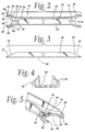
- a side piece made according to the invention and which may be used for either one or both of the side pieces 36, 38 is illustrated.
- the side piece is generally designated 42 and as illustrated in Fig. 2 is approximately bone-shaped, having enlarged ends 44, 46 with concave recesses 48 in each.
- the side piece 42 is made up of an elongated, flat metal base 49, formed of material such as aluminum when the heat exchanger is a brazed heat exchanger.
- the same is relatively narrow intermediate its ends 44, 46 and has upstanding flanges 50, 52 extending along on both sides of the base 49.
- the height of the flanges 50, 52 is greater intermediate the ends 44, 46 than at the ends 44, 46.
- the height of the flange gradually tapers downwardly in a region 54 as the ends 44, 46 arc approached.
- the side piece 42 is wider at its ends 44, 46 than at its center, the use of the tapering flange 50, 52 allows formation of the end piece out of a strip of uniform width, not withstanding the difference in width of the final product.
- the flanges 50, 52 provide resistance to bending of the base 49 and are intended to extend away from the tubes 20.
- each end 44, 46 are identical, only one will be described.
- the recesses 48 open outwardly, that is, in a direction remote from the center of the base 49 and effectively define two fingers 56, and 58 which are spaced from one another by the recess 48.
- the fingers 56 and 58 are relatively stiff, although resilient, stiffness being a result of the presence of the flanges 50, 52 and/or the thickness of the base 49. This allows the fingers 56, 58 to separate but to resiliently return to their original positions. Consequently, each end 44, 46 of a side piece 42 may he snap fit onto a corresponding end of one of the headers 10, 12.
- the space between the fingers 56, 58, i.e., the recess 48 is such as to partially surround the majority of the periphery of the corresponding end of the header as well as to frictionally grasp the same.
- the interior periphery 60 of each recess 48 is circular and of a diameter no greater than the outside diameter of the header end.
- the angular extent of the peripheral surface 60 must be greater than 180° to prevent the header end from falling out of the recess 40.
- the spacing between points 62 and 64 is less than the spacing between points 66 and 68 meaning that each recess 48 is narrower at the opening thereof than at a point intermediate the bottom 70 of the recess 48 and the opening of the recess 48.
- the angular distance between the points 62, 64 will be on the order of 210°. However, other angular spacings may be used so long as they exceed 180° and the dimensioning of the recess 48 is such as to cause good frictional gripping of the header end.
- An elongated, relatively narrow slot 74 is located in the base 49 and has one end 76 opening to the bottom 70 of the recess 48.
- the opposite end 78 terminates in an enlarged, stress relieving opening 80 which is an opening having a periphery of a continuous curve. Typically, the periphery of the opening 80 will be circular. This dissipates stress in the base 49 at that location when the fingers 56, 58 flex during the installation process.
- each opening at its outermost end, and past the points 62, 64 terminates in outwardly diverging surfaces 84 on each of the fingers which cam surfaces.
- the surfaces 84 upon encountering the cylindrical surface of the end of a header, tend to cam the fingers 56, 58 apart to allow the same to slide onto an end of one of the headers 10, 12.
- the end pieces 42 may be installed simply by aligning the ends of the headers 10, 12, with respective ones of the openings 48 and effecting relative movement between the end piece 48 and the headers 10, 12 in the direction of the elongation of the headers 10, 12.
- the end piece 42 will be made of aluminum so as to be brazed to headers 10, 12 and fins 34, also of aluminum.
- the lowermost side of the base 49 is viewed in Fig. 3, shown at 90, is conventionally provided with a cladding of braze alloy.
- the braze alloy shown at 90 will not only bond to the ends of the headers 10, 12 during a brazing process, but will bond to the crests of an adjacent serpentine fin 34 at the same time.
- the opposite side 92 of the base 49 need not be braze clad although if it is to serve as a mounting point for fixtures or the like, it may be clad as well.
Landscapes
- Engineering & Computer Science (AREA)
- Physics & Mathematics (AREA)
- Thermal Sciences (AREA)
- Mechanical Engineering (AREA)
- General Engineering & Computer Science (AREA)
- Heat-Exchange Devices With Radiators And Conduit Assemblies (AREA)
- Details Of Heat-Exchange And Heat-Transfer (AREA)
Applications Claiming Priority (2)
| Application Number | Priority Date | Filing Date | Title |
|---|---|---|---|
| US748922 | 2000-12-27 | ||
| US09/748,922 US6446711B1 (en) | 2000-12-27 | 2000-12-27 | Side piece for heat exchangers |
Publications (2)
| Publication Number | Publication Date |
|---|---|
| EP1219913A2 true EP1219913A2 (de) | 2002-07-03 |
| EP1219913A3 EP1219913A3 (de) | 2003-10-08 |
Family
ID=25011473
Family Applications (1)
| Application Number | Title | Priority Date | Filing Date |
|---|---|---|---|
| EP01130237A Withdrawn EP1219913A3 (de) | 2000-12-27 | 2001-12-19 | Verbessertes Seitenteil für Wärmetauscher |
Country Status (7)
| Country | Link |
|---|---|
| US (1) | US6446711B1 (de) |
| EP (1) | EP1219913A3 (de) |
| JP (1) | JP2002213892A (de) |
| AU (1) | AU781791B2 (de) |
| BR (1) | BR0105760A (de) |
| CA (1) | CA2364180A1 (de) |
| MX (1) | MXPA01012076A (de) |
Families Citing this family (12)
| Publication number | Priority date | Publication date | Assignee | Title |
|---|---|---|---|---|
| US6929646B2 (en) * | 2001-04-04 | 2005-08-16 | Integra Signature Technologies, Inc. | Implantable bone fracture reduction apparatus having a polymeric applicator |
| US6819824B1 (en) * | 2001-05-21 | 2004-11-16 | Calient Networks | Optical switch package |
| US7722675B2 (en) * | 2001-07-16 | 2010-05-25 | Spinecore, Inc. | Instruments for reorienting vertebral bones for the treatment of scoliosis |
| LU90827B1 (en) * | 2001-09-07 | 2003-03-10 | Delphi Tech Inc | Assembly of a component of a vehicle air conditioning system to a support structure |
| DE502004008344D1 (de) * | 2004-04-19 | 2008-12-11 | Behr France Hambach Sarl | Wärmeübertrager, insbesondere für ein Kraftfahrzeug |
| CN100513980C (zh) * | 2004-09-15 | 2009-07-15 | 贝洱两合公司 | 用于散热器的侧板 |
| US7874349B2 (en) * | 2006-03-16 | 2011-01-25 | Visteon Global Technologies, Inc. | Heat exchanger tank |
| US20070295491A1 (en) * | 2006-06-23 | 2007-12-27 | Behr America, Inc. | Device for exchanging heat |
| SE532319C2 (sv) * | 2007-07-26 | 2009-12-15 | Titanx Engine Cooling Holding | Värmeväxlare och sätt att tillverka denna |
| US20100006556A1 (en) * | 2008-07-11 | 2010-01-14 | William Home | Atmospheric heater |
| GB2507495B (en) * | 2012-10-30 | 2018-07-25 | Denso Marston Ltd | A heat exchanger assembly |
| JP6096636B2 (ja) * | 2013-10-18 | 2017-03-15 | 株式会社ティラド | コルゲートフィン型熱交換器 |
Citations (1)
| Publication number | Priority date | Publication date | Assignee | Title |
|---|---|---|---|---|
| US4615385A (en) | 1985-04-12 | 1986-10-07 | Modine Manufacturing Inc. | Heat exchanger |
Family Cites Families (18)
| Publication number | Priority date | Publication date | Assignee | Title |
|---|---|---|---|---|
| US3246691A (en) * | 1963-11-27 | 1966-04-19 | Fedders Corp | Radiators |
| FR2243037B1 (de) * | 1973-09-06 | 1977-08-05 | Chausson Usines Sa | |
| US4367793A (en) * | 1977-03-18 | 1983-01-11 | Macintosh John J | Universal radiator assembly |
| WO1984001208A1 (en) * | 1982-09-24 | 1984-03-29 | Bryce H Knowlton | Improved radiator assembly |
| DE3428857A1 (de) | 1984-08-04 | 1986-02-13 | Süddeutsche Kühlerfabrik Julius Fr. Behr GmbH & Co KG, 7000 Stuttgart | Wasser/luft-kuehler fuer wassergekuehlte verbrennungskraftmaschinen |
| US4998580A (en) | 1985-10-02 | 1991-03-12 | Modine Manufacturing Company | Condenser with small hydraulic diameter flow path |
| ES290042Y (es) * | 1985-11-04 | 1986-10-16 | Frape-Behr,S.A. | Estructura para radiador de automovil |
| FR2646697B1 (fr) | 1989-05-05 | 1991-10-31 | Hutchinson Sa | Dispositif d'assemblage par encliquetage pour echangeurs de chaleur de vehicules automobiles |
| US5257454A (en) * | 1992-01-30 | 1993-11-02 | Ford Motor Company | Method of making a heat exchanger with thermal stress relieving zone |
| JPH0694327A (ja) * | 1992-09-14 | 1994-04-05 | Showa Alum Corp | 熱交換器 |
| US5366008A (en) | 1993-08-16 | 1994-11-22 | General Motors Corporation | Method of manufacturing header condensers |
| FR2709344B1 (fr) | 1993-08-27 | 1995-10-13 | Valeo Thermique Moteur Sa | Condenseur pour installation de climatisation de véhicule automobile. |
| SE516092C2 (sv) | 1995-01-25 | 2001-11-19 | Valeo Engine Cooling Ab | Värmeväxlartank för montering i en oljekylare, förfarande för framställning av en sådantank, samt värmeväxlare |
| US5685364A (en) | 1996-03-15 | 1997-11-11 | Zexel Usa Corporation | Snap-on bracket for a condenser header |
| US5667004A (en) * | 1996-04-29 | 1997-09-16 | General Motors Corporation | Molded plastic heat exchanger mounting channel |
| GB9609440D0 (en) | 1996-05-04 | 1996-07-10 | Ford Motor Co | Radiator and condenser assembly |
| US5740772A (en) | 1996-10-18 | 1998-04-21 | Midwest Instrument Co., Inc. | Oil filter cooler |
| DE19731999A1 (de) | 1997-07-25 | 1999-02-04 | Laengerer & Reich Gmbh & Co | Kühlmodul |
-
2000
- 2000-12-27 US US09/748,922 patent/US6446711B1/en not_active Expired - Lifetime
-
2001
- 2001-11-26 MX MXPA01012076A patent/MXPA01012076A/es unknown
- 2001-11-28 AU AU95127/01A patent/AU781791B2/en not_active Ceased
- 2001-11-30 BR BR0105760-0A patent/BR0105760A/pt not_active IP Right Cessation
- 2001-11-30 CA CA002364180A patent/CA2364180A1/en not_active Abandoned
- 2001-12-19 EP EP01130237A patent/EP1219913A3/de not_active Withdrawn
- 2001-12-26 JP JP2001393818A patent/JP2002213892A/ja not_active Ceased
Patent Citations (2)
| Publication number | Priority date | Publication date | Assignee | Title |
|---|---|---|---|---|
| US4615385A (en) | 1985-04-12 | 1986-10-07 | Modine Manufacturing Inc. | Heat exchanger |
| US4615385B1 (en) | 1985-04-12 | 1994-12-20 | Modine Mfg Co | Heat exchanger |
Also Published As
| Publication number | Publication date |
|---|---|
| US20020079091A1 (en) | 2002-06-27 |
| CA2364180A1 (en) | 2002-06-27 |
| US6446711B1 (en) | 2002-09-10 |
| JP2002213892A (ja) | 2002-07-31 |
| EP1219913A3 (de) | 2003-10-08 |
| MXPA01012076A (es) | 2002-07-04 |
| BR0105760A (pt) | 2002-09-10 |
| AU9512701A (en) | 2002-07-04 |
| AU781791B2 (en) | 2005-06-16 |
Similar Documents
| Publication | Publication Date | Title |
|---|---|---|
| AU644234B2 (en) | Heat exchanger | |
| KR100237229B1 (ko) | 병류열교환기용 매니폴드 어셈블리 및 그의 제작방법 | |
| US5069277A (en) | Vehicle-loaded heat exchanger of parallel flow type | |
| US5899263A (en) | Heat exchanger | |
| US5127466A (en) | Heat exchanger with header bracket and insertable header plate | |
| US6964296B2 (en) | Heat exchanger | |
| KR102018675B1 (ko) | 연료 순환 튜브 및 연료 순환 튜브를 포함하는 열 교환기 | |
| US6446711B1 (en) | Side piece for heat exchangers | |
| US5896916A (en) | Heat exchanger suitable for a refrigerant evaporator | |
| CA2508510A1 (en) | Thermal cycling resistant tube to header joint for heat exchangers | |
| JPH06159981A (ja) | 熱交換器 | |
| JPH1114288A (ja) | 熱交換器 | |
| US20200080794A1 (en) | B-tube reform for improved thermal cycle performance | |
| US7302997B2 (en) | Vibration-resistant mounting bracket for heat exchangers | |
| KR100336847B1 (ko) | 열교환기의헤더및탱크구조 | |
| JP3995527B2 (ja) | 受液器付き熱交換器 | |
| US20070068660A1 (en) | Heat exchanging unit for motor vehicles | |
| JP2003114094A (ja) | 熱交換器用ヘッダ | |
| US10801781B2 (en) | Compliant b-tube for radiator applications | |
| KR19980070184A (ko) | 열교환기 | |
| US20070284086A1 (en) | Transition assembly and method of connecting to a heat exchanger | |
| JP7485993B1 (ja) | 熱交換器 | |
| JPH02247498A (ja) | 熱交換器 | |
| WO2002035170A1 (en) | Heat exchanger | |
| JP3807806B2 (ja) | 接続用パイプ付熱交換器用ヘッダ |
Legal Events
| Date | Code | Title | Description |
|---|---|---|---|
| PUAI | Public reference made under article 153(3) epc to a published international application that has entered the european phase |
Free format text: ORIGINAL CODE: 0009012 |
|
| AK | Designated contracting states |
Kind code of ref document: A2 Designated state(s): AT BE CH CY DE DK ES FI FR GB GR IE IT LI LU MC NL PT SE TR |
|
| AX | Request for extension of the european patent |
Free format text: AL;LT;LV;MK;RO;SI |
|
| PUAL | Search report despatched |
Free format text: ORIGINAL CODE: 0009013 |
|
| AK | Designated contracting states |
Kind code of ref document: A3 Designated state(s): AT BE CH CY DE DK ES FI FR GB GR IE IT LI LU MC NL PT SE TR |
|
| AX | Request for extension of the european patent |
Extension state: AL LT LV MK RO SI |
|
| 17P | Request for examination filed |
Effective date: 20040407 |
|
| AKX | Designation fees paid |
Designated state(s): DE FR GB IT |
|
| 17Q | First examination report despatched |
Effective date: 20051215 |
|
| GRAP | Despatch of communication of intention to grant a patent |
Free format text: ORIGINAL CODE: EPIDOSNIGR1 |
|
| STAA | Information on the status of an ep patent application or granted ep patent |
Free format text: STATUS: THE APPLICATION IS DEEMED TO BE WITHDRAWN |
|
| 18D | Application deemed to be withdrawn |
Effective date: 20070919 |