EP1219960A1 - Heizungsmuster für planare Gassensoren - Google Patents
Heizungsmuster für planare Gassensoren Download PDFInfo
- Publication number
- EP1219960A1 EP1219960A1 EP01204816A EP01204816A EP1219960A1 EP 1219960 A1 EP1219960 A1 EP 1219960A1 EP 01204816 A EP01204816 A EP 01204816A EP 01204816 A EP01204816 A EP 01204816A EP 1219960 A1 EP1219960 A1 EP 1219960A1
- Authority
- EP
- European Patent Office
- Prior art keywords
- substrate
- heater
- thermistor element
- pattern
- perimeter
- Prior art date
- Legal status (The legal status is an assumption and is not a legal conclusion. Google has not performed a legal analysis and makes no representation as to the accuracy of the status listed.)
- Withdrawn
Links
- 239000000758 substrate Substances 0.000 claims abstract description 52
- 239000000463 material Substances 0.000 claims abstract description 21
- BASFCYQUMIYNBI-UHFFFAOYSA-N platinum Chemical compound [Pt] BASFCYQUMIYNBI-UHFFFAOYSA-N 0.000 claims abstract description 16
- 238000010438 heat treatment Methods 0.000 claims abstract description 14
- KDLHZDBZIXYQEI-UHFFFAOYSA-N Palladium Chemical compound [Pd] KDLHZDBZIXYQEI-UHFFFAOYSA-N 0.000 claims abstract description 8
- 229910052697 platinum Inorganic materials 0.000 claims abstract description 8
- 238000000034 method Methods 0.000 claims abstract description 7
- 239000000203 mixture Substances 0.000 claims abstract description 6
- 229910052763 palladium Inorganic materials 0.000 claims abstract description 4
- 238000004891 communication Methods 0.000 claims description 8
- QVGXLLKOCUKJST-UHFFFAOYSA-N atomic oxygen Chemical compound [O] QVGXLLKOCUKJST-UHFFFAOYSA-N 0.000 description 22
- 239000001301 oxygen Substances 0.000 description 22
- 229910052760 oxygen Inorganic materials 0.000 description 22
- 239000007789 gas Substances 0.000 description 13
- 239000000446 fuel Substances 0.000 description 7
- PXHVJJICTQNCMI-UHFFFAOYSA-N Nickel Chemical compound [Ni] PXHVJJICTQNCMI-UHFFFAOYSA-N 0.000 description 6
- 238000005086 pumping Methods 0.000 description 6
- 239000003792 electrolyte Substances 0.000 description 4
- 238000002485 combustion reaction Methods 0.000 description 3
- 238000013461 design Methods 0.000 description 3
- 229910052759 nickel Inorganic materials 0.000 description 3
- 230000001681 protective effect Effects 0.000 description 3
- 239000007784 solid electrolyte Substances 0.000 description 3
- 238000012546 transfer Methods 0.000 description 3
- IJGRMHOSHXDMSA-UHFFFAOYSA-N Atomic nitrogen Chemical compound N#N IJGRMHOSHXDMSA-UHFFFAOYSA-N 0.000 description 2
- VYZAMTAEIAYCRO-UHFFFAOYSA-N Chromium Chemical compound [Cr] VYZAMTAEIAYCRO-UHFFFAOYSA-N 0.000 description 2
- PNEYBMLMFCGWSK-UHFFFAOYSA-N aluminium oxide Inorganic materials [O-2].[O-2].[O-2].[Al+3].[Al+3] PNEYBMLMFCGWSK-UHFFFAOYSA-N 0.000 description 2
- 229910052804 chromium Inorganic materials 0.000 description 2
- 239000011651 chromium Substances 0.000 description 2
- 238000000151 deposition Methods 0.000 description 2
- 230000008021 deposition Effects 0.000 description 2
- 229910052751 metal Inorganic materials 0.000 description 2
- 239000002184 metal Substances 0.000 description 2
- 239000004215 Carbon black (E152) Substances 0.000 description 1
- 108091008874 T cell receptors Proteins 0.000 description 1
- 230000004075 alteration Effects 0.000 description 1
- 239000011230 binding agent Substances 0.000 description 1
- 229920002678 cellulose Polymers 0.000 description 1
- 239000001913 cellulose Substances 0.000 description 1
- 239000000919 ceramic Substances 0.000 description 1
- 229910010293 ceramic material Inorganic materials 0.000 description 1
- 230000008859 change Effects 0.000 description 1
- 238000005229 chemical vapour deposition Methods 0.000 description 1
- 150000001875 compounds Chemical class 0.000 description 1
- 239000004020 conductor Substances 0.000 description 1
- 238000010276 construction Methods 0.000 description 1
- 238000005336 cracking Methods 0.000 description 1
- 230000001419 dependent effect Effects 0.000 description 1
- 239000003344 environmental pollutant Substances 0.000 description 1
- 239000012530 fluid Substances 0.000 description 1
- 239000011521 glass Substances 0.000 description 1
- PCHJSUWPFVWCPO-UHFFFAOYSA-N gold Chemical compound [Au] PCHJSUWPFVWCPO-UHFFFAOYSA-N 0.000 description 1
- 229910052737 gold Inorganic materials 0.000 description 1
- 239000010931 gold Substances 0.000 description 1
- 229930195733 hydrocarbon Natural products 0.000 description 1
- 150000002430 hydrocarbons Chemical class 0.000 description 1
- 239000001257 hydrogen Substances 0.000 description 1
- 229910052739 hydrogen Inorganic materials 0.000 description 1
- 125000004435 hydrogen atom Chemical class [H]* 0.000 description 1
- 230000006872 improvement Effects 0.000 description 1
- 238000012986 modification Methods 0.000 description 1
- 230000004048 modification Effects 0.000 description 1
- 229910052757 nitrogen Inorganic materials 0.000 description 1
- 238000000059 patterning Methods 0.000 description 1
- 231100000719 pollutant Toxicity 0.000 description 1
- 239000010970 precious metal Substances 0.000 description 1
- 230000009467 reduction Effects 0.000 description 1
- 238000007650 screen-printing Methods 0.000 description 1
- 230000035939 shock Effects 0.000 description 1
- 239000007787 solid Substances 0.000 description 1
- 239000002904 solvent Substances 0.000 description 1
- 238000004544 sputter deposition Methods 0.000 description 1
- 238000006467 substitution reaction Methods 0.000 description 1
- 230000009258 tissue cross reactivity Effects 0.000 description 1
- 238000007740 vapor deposition Methods 0.000 description 1
Images

Classifications
-
- G—PHYSICS
- G01—MEASURING; TESTING
- G01N—INVESTIGATING OR ANALYSING MATERIALS BY DETERMINING THEIR CHEMICAL OR PHYSICAL PROPERTIES
- G01N27/00—Investigating or analysing materials by the use of electric, electrochemical, or magnetic means
- G01N27/26—Investigating or analysing materials by the use of electric, electrochemical, or magnetic means by investigating electrochemical variables; by using electrolysis or electrophoresis
- G01N27/403—Cells and electrode assemblies
- G01N27/406—Cells and probes with solid electrolytes
- G01N27/4067—Means for heating or controlling the temperature of the solid electrolyte
-
- Y—GENERAL TAGGING OF NEW TECHNOLOGICAL DEVELOPMENTS; GENERAL TAGGING OF CROSS-SECTIONAL TECHNOLOGIES SPANNING OVER SEVERAL SECTIONS OF THE IPC; TECHNICAL SUBJECTS COVERED BY FORMER USPC CROSS-REFERENCE ART COLLECTIONS [XRACs] AND DIGESTS
- Y10—TECHNICAL SUBJECTS COVERED BY FORMER USPC
- Y10T—TECHNICAL SUBJECTS COVERED BY FORMER US CLASSIFICATION
- Y10T29/00—Metal working
- Y10T29/49—Method of mechanical manufacture
- Y10T29/49002—Electrical device making
- Y10T29/49007—Indicating transducer
-
- Y—GENERAL TAGGING OF NEW TECHNOLOGICAL DEVELOPMENTS; GENERAL TAGGING OF CROSS-SECTIONAL TECHNOLOGIES SPANNING OVER SEVERAL SECTIONS OF THE IPC; TECHNICAL SUBJECTS COVERED BY FORMER USPC CROSS-REFERENCE ART COLLECTIONS [XRACs] AND DIGESTS
- Y10—TECHNICAL SUBJECTS COVERED BY FORMER USPC
- Y10T—TECHNICAL SUBJECTS COVERED BY FORMER US CLASSIFICATION
- Y10T29/00—Metal working
- Y10T29/49—Method of mechanical manufacture
- Y10T29/49002—Electrical device making
- Y10T29/49082—Resistor making
- Y10T29/49083—Heater type
Definitions
- This disclosure relates to planar gas sensors, and, more particularly, to heater patterns for planar gas sensors that yield a reduction in the incidence of cracking attributable to tensile stresses at the edges of the planar gas sensors.
- Gas sensors and in particular oxygen sensors are used in combustion engines to control the air/fuel ratio in the combustion chamber so that the air/fuel ratio remains at or near its proper stoichiometric value. Maintaining the proper stoichiometric value, allows for the improvement of fuel consumption and the minimization of pollutants in an exhaust gas.
- An oxygen sensor typically includes an oxygen sensing element having an ion-conductive solid electrolytic plate on which porous electrodes are disposed. A difference in potential corresponding to the difference in oxygen content between the exhaust gas and the reference air is generated by the oxygen sensing element, is quantified, and is used to adjust the air/fuel ratio in the combustion chamber.
- the proper functioning of the oxygen sensing element is typically dependent upon its temperature. Because a significant amount of time is often required for the oxygen sensor to become heated to operating temperature after startup of the engine, the air/fuel ratio is difficult to control during that time. Heaters are, therefore, oftentimes incorporated into the oxygen sensing system to more quickly bring the oxygen sensing elements up to a temperature at which the most efficiency can be realized.
- Typical heaters in planar sensors are formed in various patterns on one face of the oxygen sensing element. Such designs attempt to create a uniform temperature profile across the sensor element by adjusting the heat input through patterning of a single heater trace. Heater patterns such as these are difficult to control because the balance of the heat input between the center and the edges of the pattern changes as the temperature changes. Variations in the heating profile oftentimes cause "hotspots" within the oxygen sensing element, which result in thermal shock.
- the oxygen sensing element is usually fabricated from a ceramic material, differing rates of expansion often cause tensile stresses to be experienced along the interfaces of the hotter and colder areas. Such tensile stresses may, over time, cause the oxygen sensing elements to fracture and function improperly, thereby communicating inaccurate information for the control of the air/fuel ratio. In such an instance, the oxygen sensor will require replacement to ensure maximum efficiency of the system operation.
- a heater pattern for a heater of a gas sensor in which a temperature profile is manipulated is described below.
- the heater pattern utilizes a thermistor element configured in such a manner so as to reduce the number of hotspots in the gas sensor.
- the heater includes a substrate and the thermistor element disposed thereon.
- the thermistor element is arranged so as to define an edge pattern extending about a perimeter of the substrate and a center pattern serially connected to the edge pattern.
- the center pattern extends over a portion of the substrate that is intermediate the perimeter of the substrate.
- the thermistor element is screen printed onto the substrate to a thickness of about 5 microns to about 50 microns, and preferably to a thickness of about 10 microns to about 40 microns.
- the edge and center patterns are furthermore preferably formed of materials having differing coefficients of thermal resistivity, e.g., platinum and platinum/palladium blends.
- a method of heating the gas sensor includes disposing the thermistor element in an electrically serial configuration about a perimeter of the substrate and over a portion of the substrate intermediate the perimeter of the substrate and pass an electric current through the thermistor element.
- a heater pattern for a heater of a planar gas sensor is described herein.
- the gas sensor could be a nitrogen sensor, a hydrogen sensor, a hydrocarbon sensor, or a similar apparatus.
- the disclosed heater pattern utilizes a thermistor element that extends about the outer edge of the heater as well as over the portion of the heater intermediate the outer edge. In such a design, the temperature differential between the edges of the heater and the center portion of the heater is minimized, thereby causing the heat transfer between the outer edge and the center portion of the heater to be minimized.
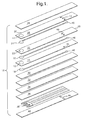
- Sensor element 10 comprises a solid electrolyte 12 disposed in a dielectric layer 14 with an inner electrode 16 and a reference electrode 18 disposed on opposite sides of solid electrolyte 12; a porous electrolyte 20 disposed in electrical communication with inner electrode 16 and disposed in a dielectric layer 22; an outer electrode 24 disposed on the side of porous electrolyte 20 opposite inner electrode 16; and a dielectric layer 26 disposed against dielectric layer 22 opposite dielectric layer 14.
- Sensor element 10 further comprises internal support layers 30, 32, 34, 36 disposed against dielectric layer 14; a heater, shown generally at 38, disposed between support layer 36 and a protective outer layer 40; a protective material 42 disposed in fluid communication with outer electrode 24 and within dielectric layer 26; vias 44 formed in dielectric layers 14, 22, 26, and outer layer 40; leads 46 in electrical communication with electrodes 16, 18, 24.
- a terminal end of sensor element 10 is shown generally at 48, and a sensor end of sensor element 10 is shown generally at 50.
- a heater pattern (not shown) is disposed on heater 38 and is described below with reference to FIGURE 2.
- Outer electrode 24, porous electrolyte 20, and inner electrode 16 form a pumping cell, while inner electrode 16, solid electrolyte 12, and reference electrode 18 form a reference cell.
- Oxygen in the exhaust gas enters the pumping cell through protective material 42 and diffuses through outer electrode 24 and porous electrolyte 20 to inner electrode 16, where the oxygen is ionized and pumped back out of the cell.
- a reference cell is used in combination with the pumping cell, but the pumping cell can be used as the only electrochemical cell in the sensor in lean-only applications.
- the reference cell is used to compare the partial pressure of oxygen at inner electrode 16 with a known oxygen partial pressure at reference electrode 18 in order to determine the potential that should be applied to the pumping cell.
- the measured current in the pumping cell will be proportional to the partial pressure of oxygen in the exhaust gas.
- Leads 46 are disposed across dielectric layers 14, 22 to electrically connect the external wiring of sensor element 10 with electrodes 16, 18, 24. Leads 46 are typically formed on the same layer as the electrode to which they are in electrical communication and extend from the electrode to the terminal end 48 of the element where they are in electrical communication with the corresponding via 44. Heater 38 also includes leads (shown below with reference to FIGURE 2) that are in electrical communication with vias 44.
- Heater 38 comprises a thermistor element, shown generally at 63, configured to define a heating section 62 and leads 68 disposed on a substrate 52 and positioned between the adjacent layers of the sensor element.
- Preferred materials for use as substrate 52 include, but are not limited to, alumina, alumina-based compounds, ceramics, glasses, cermets, and combinations of at least one of the foregoing materials.
- Heating section 62 comprises an edge pattern 64 and a center pattern 66 arranged in an electrically serial configuration.
- Edge pattern 64 extends generally about an outer edge of heating section 62 that corresponds with a perimeter of substrate 52.
- Center pattern 66 extends from edge pattern 64 substantially over a portion of heating section 62 intermediate the perimeter of substrate 52.
- Center pattern 66 is preferably arranged on substrate 52 substantially in the form of a U shape, the ends of the legs of the U shape each being in electronic communication with edge pattern 64. Such an arrangement maximizes the area of substrate 52 over which center pattern 66 is disposed. By maximizing the area over which center pattern 66 is disposed, the number of temperature differentials created within heating section 62 is minimized and heater 38 is provided with improved heating capabilities.
- heating section 62 which is selected in the design of heater 38, raises the temperature of the sensor element such that the air/fuel ratio can be adequately controlled immediately after startup of an engine (not shown) into which the sensor element incorporating heater 38 is installed and before the engine reaches its operating temperature. Because thermistor element 63 is resistive, the application of a current therethrough causes heat to be generated. The flow of current is effectuated through heater leads 68, which are disposed on the end portions of edge pattern 64 of thermistor element 63 and are connectable to a power source (not shown) that provides a flow of current to heating section 62.
- Thermistor element 63 typically comprises a precious metal that may be deposited onto substrate 52 in a myriad of ways including, but not limited to, sputtering, chemical vapor deposition, stenciling, and screen printing. Thicker depositions of material are generally screen printed or stenciled onto substrate 52, while thinner depositions of material are generally sputtered or deposited using vapor deposition techniques.
- the metal is formed into a paste, screen printed onto substrate 52, and dried. The metal is typically combined with cellulose, a binder, and a solvent to make the paste.
- each pattern 64, 66 is about 5 microns to about 50 microns thick. A preferred thickness for each pattern 64, 66 is about 10 to about 40 microns.
- center pattern 66 allows the heating characteristics of thermistor element 63 to be adjustable. These variations are effectuated by the alteration of a length L of center pattern 66. By altering length L of center pattern 66, increased contact between substrate 52 and thermistor element 63 can be maintained. Such increased contact minimizes the presence of hotspots in heater 38 and provides a more uniform temperature profile over the surface of substrate 52.
- a width W of center pattern 66 is also variable and can be manipulated to give additional flexibility in adjusting the heat input to center pattern 66.
- patterns 64, 66 may be fabricated of materials having varying thermal coefficient of resistivity (TCR) values.
- TCR thermal coefficient of resistivity
- the TCR which is typically measured in parts per million per degree temperature, is characterized by an increase in resistance for each degree increase of temperature over a given range. Materials having a high TCR are typically used for center pattern 66 so that a greater change in resistance per degree temperature can be realized. Because the heat gradient is preferably from the innermost portions of sensor to the outermost portions, materials having a TCR lower than the TCR of center pattern 66 are typically used for edge pattern 64. In such an instance, as the temperature of center pattern 66 increases, the TCR of the material from which center pattern 66 is fabricated causes a higher resistance to be realized by center pattern 66.
- center pattern 66 When this higher resistance is realized, the current through center pattern 66 is reduced, which in turn reduces the heat generated by center pattern 66.
- the disparity in temperatures between center pattern 66 and edge pattern 64 is minimized and a more uniform temperature profile across the surface of heater 38 is attained. Uniformity in the profile across the surface of heater 38 minimizes tensile stresses that result from the differing rates of expansion associated with heating section 62.
- each pattern 64, 66 can be realized through appropriate selection of conductor materials.
- the preferred material for center pattern 66 includes, but is not limited to, platinum, which has an inherent TCR of about 3928 ppm/°C.
- the preferred material for edge pattern 64 includes, but is not limited to, a blend of platinum and palladium.
- the preferred materials for leads 68 include, but are not limited to, nickel, blends of nickel and chromium, and blends of nickel, chromium, and gold.
- the power source supplies battery voltage to patterns 64, 66.
- center pattern 66 is generally fabricated of a material having a higher TCR value than edge pattern 64 has, and because the resistance of center pattern 66 preferably varies to a greater degree than does the resistance of edge pattern 64 due to the materials of construction, a temperature gradient associated with heater 38 typically results in the transfer of heat from the inner portions of substrate 52 to the edge portions of substrate 52. Because of such a transfer of heat, a more uniform temperature profile across heater 38 is realized.
Landscapes
- Chemical & Material Sciences (AREA)
- Life Sciences & Earth Sciences (AREA)
- Health & Medical Sciences (AREA)
- Physics & Mathematics (AREA)
- Chemical Kinetics & Catalysis (AREA)
- Electrochemistry (AREA)
- Molecular Biology (AREA)
- Analytical Chemistry (AREA)
- Biochemistry (AREA)
- General Health & Medical Sciences (AREA)
- General Physics & Mathematics (AREA)
- Immunology (AREA)
- Pathology (AREA)
- Investigating Or Analyzing Materials By The Use Of Fluid Adsorption Or Reactions (AREA)
Applications Claiming Priority (2)
| Application Number | Priority Date | Filing Date | Title |
|---|---|---|---|
| US741597 | 2000-12-19 | ||
| US09/741,597 US6435005B1 (en) | 2000-12-19 | 2000-12-19 | Heater patterns for planar gas sensors |
Publications (1)
| Publication Number | Publication Date |
|---|---|
| EP1219960A1 true EP1219960A1 (de) | 2002-07-03 |
Family
ID=24981369
Family Applications (1)
| Application Number | Title | Priority Date | Filing Date |
|---|---|---|---|
| EP01204816A Withdrawn EP1219960A1 (de) | 2000-12-19 | 2001-12-10 | Heizungsmuster für planare Gassensoren |
Country Status (2)
| Country | Link |
|---|---|
| US (1) | US6435005B1 (de) |
| EP (1) | EP1219960A1 (de) |
Cited By (1)
| Publication number | Priority date | Publication date | Assignee | Title |
|---|---|---|---|---|
| ES2564759A1 (es) * | 2015-07-30 | 2016-03-28 | Francisco Albero S.A.U. | Sensor de gas |
Families Citing this family (13)
| Publication number | Priority date | Publication date | Assignee | Title |
|---|---|---|---|---|
| US7301125B2 (en) * | 2001-05-31 | 2007-11-27 | Ric Investments, Llc | Heater for optical gas sensor |
| US7279133B2 (en) * | 2001-12-20 | 2007-10-09 | Delphi Technologies, Inc. | Planar sensor and a method for measuring the temperature of same |
| US6786076B2 (en) * | 2002-11-25 | 2004-09-07 | Reliable Instruments Llc | Thin film gas sensor |
| EP1717566A1 (de) * | 2005-04-25 | 2006-11-02 | Mettler-Toledo AG | Thermoanalytischer Sensor |
| US7611612B2 (en) | 2005-07-14 | 2009-11-03 | Ceramatec, Inc. | Multilayer ceramic NOx gas sensor device |
| US7887685B2 (en) * | 2005-07-14 | 2011-02-15 | Caterpillar Inc. | Multilayer gas sensor having dual heating zones |
| JP2007093572A (ja) * | 2005-08-29 | 2007-04-12 | Shinko Electric Ind Co Ltd | 固体電解質ガスセンサ |
| JP4826461B2 (ja) * | 2006-12-15 | 2011-11-30 | 株式会社デンソー | セラミックヒータ及びこれを用いたガスセンサ素子 |
| GB0814452D0 (en) * | 2008-08-07 | 2008-09-10 | Melexis Nv | Laminated temperature sensor |
| JP2013530396A (ja) * | 2010-06-04 | 2013-07-25 | デルファイ・テクノロジーズ・インコーポレーテッド | 低コスト同時焼成センサ加熱回路 |
| US9164080B2 (en) | 2012-06-11 | 2015-10-20 | Ohio State Innovation Foundation | System and method for sensing NO |
| CN108195875B (zh) * | 2017-12-12 | 2020-01-21 | 中国科学院过程工程研究所 | 一种宽温区快速自动化测定相变材料冷热循环的系统及其测定方法 |
| KR102078880B1 (ko) * | 2019-10-25 | 2020-04-07 | 오준우 | 원터치형 운전연수용 보조브레이크 |
Citations (4)
| Publication number | Priority date | Publication date | Assignee | Title |
|---|---|---|---|---|
| JPS60142241A (ja) * | 1983-12-28 | 1985-07-27 | Ngk Spark Plug Co Ltd | ヒ−タ−付き感ガスセンサ− |
| JPH05209854A (ja) * | 1992-01-30 | 1993-08-20 | Shinagawa Refract Co Ltd | 加熱式ガスセンサ |
| US5342498A (en) * | 1991-06-26 | 1994-08-30 | Graves Jeffrey A | Electronic wiring substrate |
| EP0963829A1 (de) * | 1998-06-12 | 1999-12-15 | Husky Injection Molding Systems Ltd. | Giesssystem mit Filmheizungen und/oder -Sensoren |
Family Cites Families (17)
| Publication number | Priority date | Publication date | Assignee | Title |
|---|---|---|---|---|
| US4146957A (en) | 1977-01-17 | 1979-04-03 | Engelhard Minerals & Chemicals Corporation | Thick film resistance thermometer |
| JPS5853862B2 (ja) * | 1978-02-20 | 1983-12-01 | 松下電器産業株式会社 | 可燃性ガス検知素子 |
| US4413502A (en) * | 1981-04-27 | 1983-11-08 | Nippon Soken, Inc. | Gas detecting sensor |
| US4453397A (en) * | 1981-08-17 | 1984-06-12 | Nippon Soken, Inc. | Gas detecting sensor |
| US4520653A (en) * | 1983-08-29 | 1985-06-04 | Ford Motor Company | Circuits for obtaining a voltage reading from a sensing element |
| JPS61109289A (ja) * | 1984-11-01 | 1986-05-27 | 日本碍子株式会社 | セラミツクヒ−タおよびその製造方法 |
| JPH0663799B2 (ja) | 1987-10-05 | 1994-08-22 | 株式会社村田製作所 | 熱型流量検出装置 |
| JPH01194282A (ja) * | 1988-01-28 | 1989-08-04 | Ngk Insulators Ltd | セラミック・ヒータ及び電気化学的素子並びに酸素分析装置 |
| US5288389A (en) | 1988-04-01 | 1994-02-22 | Ngk Spark Plug Co., Ltd. | Oxygen sensor with higher resistance to repeated thermal-shocks and shorter warm-up time |
| FR2636737B1 (fr) * | 1988-09-16 | 1993-12-03 | Thomson Csf | Capteur de type resistif, de mesure de concentrations relatives d'especes reactives fluides, compense en temperature |
| US5895591A (en) | 1994-07-06 | 1999-04-20 | Ngk Spark Plug Co., Ltd. | Ceramic heater and oxygen sensor |
| JP3501189B2 (ja) * | 1995-06-07 | 2004-03-02 | 株式会社デンソー | 空燃比センサ素子 |
| US5544640A (en) * | 1995-07-03 | 1996-08-13 | Chrysler Corporation | System and method for heating an oxygen sensor via multiple heating elements |
| US5777207A (en) * | 1995-11-27 | 1998-07-07 | Lg Electronics Inc. | Gas sensor and method for fabricating the same |
| JP3027726B2 (ja) * | 1996-06-05 | 2000-04-04 | 日本特殊陶業株式会社 | ヒータ付き酸素センサ |
| TW366417B (en) * | 1997-10-27 | 1999-08-11 | Nat Science Council | Integrated high-performance gas sensor and the manufacturing method |
| GB9802940D0 (en) * | 1998-02-11 | 1998-04-08 | Cbl Ceramics Ltd | Gas sensor |
-
2000
- 2000-12-19 US US09/741,597 patent/US6435005B1/en not_active Expired - Fee Related
-
2001
- 2001-12-10 EP EP01204816A patent/EP1219960A1/de not_active Withdrawn
Patent Citations (4)
| Publication number | Priority date | Publication date | Assignee | Title |
|---|---|---|---|---|
| JPS60142241A (ja) * | 1983-12-28 | 1985-07-27 | Ngk Spark Plug Co Ltd | ヒ−タ−付き感ガスセンサ− |
| US5342498A (en) * | 1991-06-26 | 1994-08-30 | Graves Jeffrey A | Electronic wiring substrate |
| JPH05209854A (ja) * | 1992-01-30 | 1993-08-20 | Shinagawa Refract Co Ltd | 加熱式ガスセンサ |
| EP0963829A1 (de) * | 1998-06-12 | 1999-12-15 | Husky Injection Molding Systems Ltd. | Giesssystem mit Filmheizungen und/oder -Sensoren |
Non-Patent Citations (2)
| Title |
|---|
| PATENT ABSTRACTS OF JAPAN vol. 009, no. 312 (P - 411) 7 December 1985 (1985-12-07) * |
| PATENT ABSTRACTS OF JAPAN vol. 017, no. 643 (P - 1651) 29 November 1993 (1993-11-29) * |
Cited By (1)
| Publication number | Priority date | Publication date | Assignee | Title |
|---|---|---|---|---|
| ES2564759A1 (es) * | 2015-07-30 | 2016-03-28 | Francisco Albero S.A.U. | Sensor de gas |
Also Published As
| Publication number | Publication date |
|---|---|
| US6435005B1 (en) | 2002-08-20 |
| US20020073765A1 (en) | 2002-06-20 |
Similar Documents
| Publication | Publication Date | Title |
|---|---|---|
| US6435005B1 (en) | Heater patterns for planar gas sensors | |
| US4883947A (en) | Resistance ceramic heater with mutually connected heat-generating conductors, and electrochemical element or oxygen analyzer using such ceramic heater | |
| US4450065A (en) | Oxygen sensor | |
| JP3855483B2 (ja) | 積層型空燃比センサ素子 | |
| US4952903A (en) | Ceramic heater having portions connecting heat-generating portion and lead portions | |
| US20030146093A1 (en) | Oxygen sensor | |
| GB2046921A (en) | Measuring sensor for determining the constituents of flowing gases | |
| US20110139618A1 (en) | Ceramic exhaust gas sensor | |
| EP1219961B1 (de) | Planarer Gassensor mit gemustertem Heizelement | |
| WO2007011713A9 (en) | MULTILAYER CERAMIC NOx GAS SENSOR DEVICE | |
| US4863584A (en) | Apparatus for sensing air-fuel ratio | |
| EP0238081B1 (de) | Gasempfindliches Dickschichtelement | |
| US10837937B2 (en) | Ceramic heater, sensor element, and gas sensor | |
| US11768169B2 (en) | Ceramic heater, sensor element, and gas sensor | |
| US6951601B1 (en) | Oxygen concentration detector | |
| US20020100697A1 (en) | Gas sensor with uniform heating and method of making same | |
| US11047825B2 (en) | Ceramic heater, sensor element, and gas sensor | |
| CN101542276A (zh) | 具有保护层的氧气传感器 | |
| JP6674211B2 (ja) | セラミックスヒータ,センサ素子及びガスセンサ | |
| JP7078584B2 (ja) | セラミックスヒータ,センサ素子及びガスセンサ | |
| JP3020013B2 (ja) | 酸素センサ用セラミックヒータ | |
| JP2002357589A (ja) | ガスセンサ素子及びガスセンサ | |
| EP0360159A2 (de) | Verfahren zur Herstellung dickschichtiger Gasfühler mit einer besseren Stabilität | |
| JP6873298B2 (ja) | セラミックスヒータ,センサ素子及びガスセンサ | |
| JP2003014690A (ja) | ガスセンサ素子及びガスセンサ |
Legal Events
| Date | Code | Title | Description |
|---|---|---|---|
| PUAI | Public reference made under article 153(3) epc to a published international application that has entered the european phase |
Free format text: ORIGINAL CODE: 0009012 |
|
| AK | Designated contracting states |
Kind code of ref document: A1 Designated state(s): AT BE CH CY DE DK ES FI FR GB GR IE IT LI LU MC NL PT SE TR |
|
| AX | Request for extension of the european patent |
Free format text: AL;LT;LV;MK;RO;SI |
|
| 17P | Request for examination filed |
Effective date: 20030103 |
|
| AKX | Designation fees paid |
Designated state(s): DE FR GB |
|
| STAA | Information on the status of an ep patent application or granted ep patent |
Free format text: STATUS: THE APPLICATION IS DEEMED TO BE WITHDRAWN |
|
| 18D | Application deemed to be withdrawn |
Effective date: 20080701 |