EP1220005A2 - Microscope - Google Patents
Microscope Download PDFInfo
- Publication number
- EP1220005A2 EP1220005A2 EP01127889A EP01127889A EP1220005A2 EP 1220005 A2 EP1220005 A2 EP 1220005A2 EP 01127889 A EP01127889 A EP 01127889A EP 01127889 A EP01127889 A EP 01127889A EP 1220005 A2 EP1220005 A2 EP 1220005A2
- Authority
- EP
- European Patent Office
- Prior art keywords
- tube lens
- reflector
- spectral range
- changer
- duv
- Prior art date
- Legal status (The legal status is an assumption and is not a legal conclusion. Google has not performed a legal analysis and makes no representation as to the accuracy of the status listed.)
- Granted
Links
Images


Classifications
-
- G—PHYSICS
- G02—OPTICS
- G02B—OPTICAL ELEMENTS, SYSTEMS OR APPARATUS
- G02B21/00—Microscopes
- G02B21/18—Arrangements with more than one light path, e.g. for comparing two specimens
Definitions
- the invention relates to a microscope with a switching option for optional working in the far ultraviolet or in the visible spectral range, with an adjustable tube lens changer with at least one tube lens for the far ultraviolet spectral range and at least one Tube lens for the visible spectral range.
- the resolution of a microscope essentially depends on the wavelength of the illuminating light used.
- Conventional microscopes are operated with light in the visible wavelength range (hereinafter briefly referred to as the VIS spectral range - for English " vis ible”).
- the VIS spectral range - for English " vis ible”
- imaging at shorter wavelengths in the deep-ultraviolet range of the light spectrum (hereinafter referred to as DUV spectral range for English " d eep u ltra v iolet”) is required
- DUV spectral range for English " d eep u ltra v iolet” In the DUV mode, the microscope image is made visible with a TV camera that is sensitive to the DUV light.
- a DUV microscope preferably corresponds to the semiconductor industry Switching options between VIS and DUV optics and each associated lighting on, which also switches between VIS and DUV lenses is made.
- the lenses that are highly corrected for image errors are the most popular most manufacturers count for an infinity beam path and form with it a compensation lens. That means that with the correction the image error is a first part of the image errors in the lens and the remaining Proportion of image errors in the tube lens is corrected.
- a tube lens like the name suggests, from a single lens, but can from lens groups or be constructed a tube lens system. It therefore has to be different Lenses that are calculated for different spectral ranges, one each different, for the lens in question and the one in question Spectral range compensating tube lens introduced into the beam path become.
- Such a compensation system of objective and tube lens is described for example in DE 199 31 949 A1.
- a tube lens does not have to be only one certain lens, but also a certain reflector or filters can be assigned. This is done with the known microscopes appropriate adjustment of the tube lens changer via its own motorized Drive of the tube lens changer. The assignment of the motor adjustable reflectors (or filters) on the one hand and the corresponding The tube lens, on the other hand, is then software-based.
- a disadvantage of this known adjustment and assignment of the tube lens changer or the tube lens is on the one hand the complex and space-intensive Use of a motor drive for the tube lens changer and on the other hand the fact that a program malfunction or a program failure incorrect assignment of reflector and tube lens when working in UV light range can lead.
- the object of the invention is a microscope with a simple and safe switchover option for optional To create work in the far ultraviolet or in the visible spectral range.
- the solution to this problem is characterized according to the invention in that that the reflector carrier on the one hand and the tube lens changer on the other hand, are mechanically coupled to one another in such a way that the adjustment of the reflector carrier in the illumination beam path to a specific one
- the reflector automatically adjusts the tube lens changer so that it is one arranges the corresponding tube lens in the optical axis.
- the forced coupling between reflector carrier and tube lens changer via at least one driver pin, which is defined as on the reflector carrier Pin is formed in a corresponding receptacle of the tube lens changer engages and this when adjusting the reflector carrier inevitably takes along.
- the tube lens changer is advantageously space-saving as a rotatably mounted one Disc formed, the angle of rotation for adjusting the tube lenses is limited in the optical axis by adjustable stops.
- the invention proposes to form this as a linear slide, since such a slide along a Linear guide can be moved safely and precisely. This is in the present Case all the more important because the movement of the Reflector holder directly adjusts the tube lens changer.
- the invention proposes that the linear slide is driven by a motor.
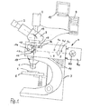
- FIG. 1 The structure of a microscope, in this case an incident light microscope, is shown schematically in FIG. 1 .
- the microscope shown essentially consists of two optical systems, an objective 1 and an eyepiece 2, which are connected to each other by a tube 3, an illumination device 4 and an object table 5 for receiving a sample 6 to be examined and a stand 7 for holding the optical parts.
- the illumination device 4 of this incident light microscope consists of an in a lamp housing 4a arranged light source 4b, the light along the optical axis 11 of the illuminating beam path via illuminating optics 4c and apertures 4d is directed onto a reflector 12 in order to to be deflected onto the sample 6 arranged on the object table 5.
- the reflector deflecting the light beam of the illuminating beam path 12 is arranged on a reflector carrier 13 designed as a linear slide, which carries several reflectors or filters 12, depending on the selected Spectral range and contrast method can be introduced into the optical axis.
- the reflector carrier 13 is motorized via a drive 14 drivable.
- a tube lens changer 16 is arranged above the reflector carrier 13, via which a corresponding tube lens 17 can be pivoted into the optical axis 15 depending on the selected contrast method and thus the chosen reflector 12.
- the tube lens changer 16 is designed as a disk that can be pivoted about a pivot point 18.
- a beam splitter 19 is also arranged.
- the assignment of a specific tube lens 17 to a specific contrast method and thus reflector 12 takes place in such a way that accordingly a suitable lens for the selected spectral range (VIS or DUV) is selected and this one the associated for the compensation system Tube lens is assigned.
- the microscope shown is for this purpose designed so that when arranging the DUV reflector 12 by means of the reflector carrier 13 the tube lens changer automatically in the illumination beam path 16 is operated so that a DUV tube lens 17 in the optical Axis 15 of the viewing beam path arranged and thus the matching Objective is assigned.
- the reflector carrier 13 on the one hand and the tube lens changer 16 on the other hand are mechanically positively coupled to one another via a driver pin 20.
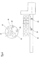
- the exact structure of the reflector carrier 13 designed as a linear slide and of the tube lens carrier 16 can be seen in FIGS. 2 to 5 .
- the tube lens changer 16 is arranged in the viewing beam path above the reflector carrier 13 and is equipped with two tube lenses 17 according to FIGS. 2 to 4 , namely a DUV tube lens 17a for the DUV spectral range and a VIS tube lens 17b for the visible VIS lens. spectral range.
- a DUV tube lens 17a for the DUV spectral range
- a VIS tube lens 17b for the visible VIS lens.
- spectral range This is a particularly advantageous embodiment, since the respective DUV tube lens 17a is calculated and designed in such a way that it forms a compensation system with various DUV lenses and can be used for all work in DUV operation. Likewise, the VIS tube lens 17b is calculated and designed in such a way that it forms a compensation system with different VIS lenses and can be used for all work in VIS operation.
- VIS tube lenses can also be used with different VIS lenses as well as different for different DUV lenses DUV tube lenses can be provided (not shown here).
- the tube lens changer 16 can be pivoted about the pivot point 18 between the end positions shown in FIGS . 2 and 3 , the twist angle in the end positions being limited by stops 21.
- the stops 21 are designed to be adjustable.
- the tube lens changer 16 has a spring 22 which prestresses the tube lens changer in the end positions against the respective stop 21 in order to hold the respective tube lens 17 securely in the correct position in the optical axis 15.
- the driver pin 20 shown schematically in FIG. 1 which mechanically forcibly couples the reflector carrier 13 on the one hand and the tube lens changer 16 on the other hand, is fixed on the reflector carrier 13 at the level of the DUV reflector 12. As can be seen from FIGS. 2 and 3 , the driver pin 20 engages in a receptacle 23 formed in the tube lens changer 16 when moving from the position of the reflector carrier 13 shown in FIG. 2 to the position shown in FIG. 3 .
- each tube lens 17 can be designed as a lens system composed of a plurality of lenses.
- FIG. 5 shows an alternative embodiment of reflector carrier 13 and tube lens changer 16.
- tube lens changer 16 is equipped with three tube lenses 17.
- the reflector carrier 13 has two driver pins 20, which can each enter a corresponding receptacle 23 of the tube lens changer 16 in order to adjust the tube lens changer 16 to the tube lens 17 corresponding to the respective reflector 12.
Landscapes
- Physics & Mathematics (AREA)
- Chemical & Material Sciences (AREA)
- Analytical Chemistry (AREA)
- General Physics & Mathematics (AREA)
- Optics & Photonics (AREA)
- Microscoopes, Condenser (AREA)
- Lens Barrels (AREA)
Abstract
Description
Die Erfindung betrifft ein Mikroskop mit einer Umschaltungsmöglichkeit für wahlweises Arbeiten im fernen ultravioletten oder im sichtbaren Spektralbereich, mit einem verstellbaren Tubuslinsenwechsler mit mindestens einer Tubuslinse für den fernen ultravioletten Spektralbereich sowie mindestens einer Tubuslinse für den sichtbaren Spektralbereich.The invention relates to a microscope with a switching option for optional working in the far ultraviolet or in the visible spectral range, with an adjustable tube lens changer with at least one tube lens for the far ultraviolet spectral range and at least one Tube lens for the visible spectral range.
Die Auflösung eines Mikroskops hängt wesentlich von der Wellenlänge des verwendeten Beleuchtungslichts ab. Konventionelle Mikroskope werden mit Licht im sichtbaren Wellenlängenbereich (nachfolgend kurz als VIS-Spektralbereich - für englisch "visible"- bezeichnet) betrieben. Zur Auflösung extrem kleiner Strukturen, z.B. auf Wafern oder Schaltungen in der Halbleiterindustrie, ist eine Abbildung bei kürzeren Wellenlängen im tief-ultravioletten Bereich des Lichtspektrums (nachfolgend kurz als DUV-Spektralbereich- für englisch "deep ultraviolet"- bezeichnet) erforderlich. Das Mikroskopbild wird im DUV-Betrieb dabei mit einer für das DUV-Licht empfindlichen TV-Kamera sichtbar gemacht.The resolution of a microscope essentially depends on the wavelength of the illuminating light used. Conventional microscopes are operated with light in the visible wavelength range (hereinafter briefly referred to as the VIS spectral range - for English " vis ible"). In order to resolve extremely small structures, for example on wafers or circuits in the semiconductor industry, imaging at shorter wavelengths in the deep-ultraviolet range of the light spectrum (hereinafter referred to as DUV spectral range for English " d eep u ltra v iolet") is required , In the DUV mode, the microscope image is made visible with a TV camera that is sensitive to the DUV light.
Die Materialien in konventionellen Optiken, die für den VIS-Spektralbereich geeignet sind, sind im DUV-Spektralbereich nicht durchlässig. Daher sind beim DUV-Betrieb des Mikroskops aus speziellen Materialien aufgebaute Optiken wie Prismen, Strahlteiler, Tubuslinsen sowie auch Objektive erforderlich, die für DUV-Wellenlängen korrigiert sind. Um den zukünftigen Anforderungen der Halbleiter-Industrie zu entsprechen, weist ein DUV-Mikroskop vorzugsweise Umschaltungsmöglichkeiten zwischen VIS- und DUV-Optiken und der jeweils zugehörigen Beleuchtung auf, bei der auch eine Umschaltung zwischen VIS- und DUV-Objektiven vorgenommen wird.The materials in conventional optics for the VIS spectral range are not transparent in the DUV spectral range. Therefore are Optics built from special materials during DUV operation of the microscope such as prisms, beam splitters, tube lenses and lenses are required, which are corrected for DUV wavelengths. To meet future requirements A DUV microscope preferably corresponds to the semiconductor industry Switching options between VIS and DUV optics and each associated lighting on, which also switches between VIS and DUV lenses is made.
Heutzutage sind die bezüglich der Bildfehler hochauskorrigierten Objektive der meisten Hersteller für einen Unendlich-Strahlengang gerechnet und bilden mit einer Tubuslinse ein Kompensationssystem. Das heißt, dass bei der Korrektion der Bildfehler ein erster Anteil der Bildfehler im Objektiv und der verbleibende Anteil der Bildfehler in der Tubuslinse auskorrigiert wird. Entsprechend besteht dann eine Tubuslinse auch nicht mehr zwingend, wie die Bezeichnung vermuten lässt, aus einer Einzellinse, sondern kann aus Linsengruppen bzw. einem Tubuslinsensystem aufgebaut sein. Es muss daher für verschiedene Objektive, die für unterschiedliche Spektralbereiche gerechnet sind, eine jeweils unterschiedliche, für das betreffende Objektiv und den betreffenden Spektralbereich kompensierende Tubuslinse in den Strahlengang eingebracht werden. Ein solches Kompensationssystem aus Objektiv und Tubuslinse ist beispielsweise in der DE 199 31 949 A1 beschrieben.Nowadays, the lenses that are highly corrected for image errors are the most popular most manufacturers count for an infinity beam path and form with it a compensation lens. That means that with the correction the image error is a first part of the image errors in the lens and the remaining Proportion of image errors in the tube lens is corrected. Corresponding then there is no longer a tube lens, like the name suggests, from a single lens, but can from lens groups or be constructed a tube lens system. It therefore has to be different Lenses that are calculated for different spectral ranges, one each different, for the lens in question and the one in question Spectral range compensating tube lens introduced into the beam path become. Such a compensation system of objective and tube lens is described for example in DE 199 31 949 A1.
Bei einem Mikroskop mit einer Umschaltungsmöglichkeit für wahlweises Arbeiten im fernen ultravioletten oder im sichtbaren Spektralbereich erfolgt dabei die Kompensation stets für den gewählten Spektralbereich. Bei einer Umschaltung des verwendeten Spektralbereichs muss daher auch der Tubuslinsenwechsler auf eine passende Tubuslinse eingestellt werden.With a microscope with a switchover option for optional work in the far ultraviolet or in the visible spectral range compensation always for the selected spectral range. When switching of the spectral range used must therefore also be the tube lens changer be adjusted to a suitable tube lens.
Bei den bekannten Mikroskopen, die sowohl für Arbeiten im DUV-Spektralbereich als auch im VIS-Spektralbereich ausgelegt sind, sind zusätzlich im Beleuchtungsstrahlengang verschiedene Reflektoren und Filter einstellbar, die für verschiedene Mikroskopier- und Kontrastverfahren (wie beispielsweise Hellfeld-, Dunkelfeld-, Interferenz-Kontrast- und DUV- Verfahren) vorgesehen und auf einem Reflektorträger angeordnet sind. Die Einstellung kann per Hand oder vorzugsweise motorisch erfolgen In the known microscopes, both for work in the DUV spectral range as well as in the VIS spectral range are additional various reflectors and filters can be set in the illumination beam path, for different microscopy and contrast methods (such as Brightfield, darkfield, interference contrast and DUV methods) provided and arranged on a reflector carrier. The setting can be done by hand or preferably by motor
Je nach Einstellung des Mikroskops muss eine Tubuslinse nicht nur einem bestimmten Objektiv, sondern zusätzlich noch einem bestimmten Reflektor oder Filter zugeordnet werden. Bei den bekannten Mikroskopen erfolgt das entsprechende Verstellen des Tubuslinsenwechslers über einen eigenen motorischen Antrieb des Tubuslinsenwechslers. Die Zuordnung der motorisch verstellbaren Reflektoren (bzw. auch Filter) einerseits und der entsprechenden Tubuslinse andererseits erfolgt dann softwaremäßig.Depending on the setting of the microscope, a tube lens does not have to be only one certain lens, but also a certain reflector or filters can be assigned. This is done with the known microscopes appropriate adjustment of the tube lens changer via its own motorized Drive of the tube lens changer. The assignment of the motor adjustable reflectors (or filters) on the one hand and the corresponding The tube lens, on the other hand, is then software-based.
Nachteilig bei dieser bekannten Verstellung und Zuordnung des Tubuslinsenwechslers bzw. der Tubuslinse ist einerseits der aufwendige und platzintensive Einsatz eines motorischen Antriebs für den Tubuslinsenwechsler und andererseits der Umstand, dass eine Programmstörung oder ein Programmausfall zu einer falschen Zuordnung von Reflektor und Tubuslinse beim Arbeiten im UV-Lichtbereich führen kann.A disadvantage of this known adjustment and assignment of the tube lens changer or the tube lens is on the one hand the complex and space-intensive Use of a motor drive for the tube lens changer and on the other hand the fact that a program malfunction or a program failure incorrect assignment of reflector and tube lens when working in UV light range can lead.
Davon ausgehend liegt der Erfindung die Aufgabe zugrunde, ein Mikroskop mit einer einfachen und sicheren Umschaltungsmöglichkeit für wahlweises Arbeiten im fernen ultravioletten oder im sichtbaren Spektralbereich zu schaffen.Proceeding from this, the object of the invention is a microscope with a simple and safe switchover option for optional To create work in the far ultraviolet or in the visible spectral range.
Die Lösung dieser Aufgabenstellung ist erfindungsgemäß dadurch gekennzeichnet, dass der Reflektorträger einerseits und der Tubuslinsenwechsler andererseits derart mechanisch miteinander gekoppelt sind, dass das Einstellen des Reflektorträgers im Beleuchtungsstrahlengang auf einen bestimmten Reflektor den Tubuslinsenwechsler automatisch so verstellt, dass dieser eine dem Reflektor entsprechende Tubuslinse in der optischen Achse anordnet.The solution to this problem is characterized according to the invention in that that the reflector carrier on the one hand and the tube lens changer on the other hand, are mechanically coupled to one another in such a way that the adjustment of the reflector carrier in the illumination beam path to a specific one The reflector automatically adjusts the tube lens changer so that it is one arranges the corresponding tube lens in the optical axis.
Durch die erfindungsgemäße mechanische Zwangskopplung der Bewegung des Reflektorträgers mit der des Tubuslinsenwechsler kann auf einen eigenen Antrieb für den Tubuslinsenwechsler verzichtet werden. Darüber hinaus ist die mechanische Kopplung der beiden Baugruppen so ausgelegt, dass beispielsweise automatisch dem Reflektor für Untersuchungen im DUV-Spektralbereich eine DUV-Tubuslinse zugeordnet ist. Damit entfällt die Notwendigkeit einer separaten und somit auch fehleranfälligen softwaremäßigen oder ähnlichen Zuordnung der Baugruppen zueinander. Due to the mechanical forced coupling of the movement according to the invention of the reflector carrier with that of the tube lens changer can be on its own Drive for the tube lens changer can be dispensed with. In addition, the mechanical coupling of the two modules designed so that, for example automatically the reflector for investigations in the DUV spectral range a DUV tube lens is assigned. This eliminates the need a separate and therefore error-prone software-based one or similar assignment of the modules to each other.
Gemäß einer praktischen Ausführungsform der Erfindung wird vorgeschlagen, dass die Zwangskopplung zwischen Reflektorträger und Tubuslinsenwechsler über mindestens einen Mitnehmerstift erfolgt, der als am Reflektorträger festgelegter Stift ausgebildet ist, der in eine entsprechende Aufnahme des Tubuslinsenwechslers eingreift und diesen beim Verstellen des Reflektorträgers zwangsläufig mitnimmt.According to a practical embodiment of the invention, it is proposed that that the forced coupling between reflector carrier and tube lens changer via at least one driver pin, which is defined as on the reflector carrier Pin is formed in a corresponding receptacle of the tube lens changer engages and this when adjusting the reflector carrier inevitably takes along.
Der Tubuslinsenwechsler ist vorteilhafterweise platzsparend als drehbar gelagerte Scheibe ausgebildet, deren Verdrehwinkel zum Einstellen der Tubuslinsen in die optische Achse durch justierbare Anschläge begrenzbar ist.The tube lens changer is advantageously space-saving as a rotatably mounted one Disc formed, the angle of rotation for adjusting the tube lenses is limited in the optical axis by adjustable stops.
Um den Tubuslinsenwechsler und somit die Tubuslinsen positionsgenau in den Enlagen des Verdrehwinkels zu halten, wird weiterhin vorgeschlagen, dass der Tubuslinsenwechsler in den Endlagen in Richtung auf die Anschläge federbelastet ist.Around the tube lens changer and thus the tube lenses in position keeping the end of the twist angle is also proposed that the tube lens changer in the end positions in the direction of the stops is spring loaded.
Zur Ausbildung des Reflektorträgers wird mit der Erfindung vorgeschlagen, diesen als Linearschieber auszubilden, da ein solcher Schieber entlang einer Linearführung sicher und positionsgenau verfahrbar ist. Dies ist im vorliegenden Fall um so wichtiger, da aufgrund der Zwangskopplung die Bewegung des Reflektorträgers direkt die Verstellung des Tubuslinsenwechslers bewirkt.To form the reflector carrier, the invention proposes to form this as a linear slide, since such a slide along a Linear guide can be moved safely and precisely. This is in the present Case all the more important because the movement of the Reflector holder directly adjusts the tube lens changer.
Schließlich wird mit der Erfindung vorgeschlagen, dass der Linearschieber motorisch antreibbar ist.Finally, the invention proposes that the linear slide is driven by a motor.
Weitere Merkmale und Vorteile der Erfindung ergeben sich anhand der nachfolgenden Beschreibung der zugehörigen Zeichnung, in der zwei Ausführungsformen eines erfindungsgemäßen Mikroskops nur beispielhaft schematisch dargestellt sind. In der Zeichnung zeigt:
- Fig. 1
- eine teilweise geschnittene schematische Darstellung des Aufbaus eines Mikroskops;
- Fig. 2
- eine schematische Draufsicht auf einen Tubuslinsenwechseler und einen Reflektorträger gemäß der Erfindung, den Tubuslinsenwechsler in einer ersten Endlage darstellend;
- Fig. 3
- eine Fig. 2 entsprechende Ansicht, jedoch den Tubuslinsenwechsler in einer zweiten Endlage darstellend;
- Fig. 4
- eine Fig. 3 entsprechende Ansicht, jedoch den Tubuslinsenwechsler und den Reflektorträger nebeneinander darstellend;
- Fig. 5
- eine schematische Ansicht einer zweiten erfindungsgemäßen Ausführungsform von Tubuslinsenwechsler und Reflektorträger.
- Fig. 1
- a partially sectioned schematic representation of the structure of a microscope;
- Fig. 2
- is a schematic plan view of a tube lens changer and a reflector support according to the invention, showing the tube lens changer in a first end position;
- Fig. 3
- a view corresponding to FIG. 2, but showing the tube lens changer in a second end position;
- Fig. 4
- a view corresponding to FIG. 3, but showing the tube lens changer and the reflector carrier next to one another;
- Fig. 5
- is a schematic view of a second embodiment of the tube lens changer and reflector carrier according to the invention.
In Fig. 1 ist schematisch der Aufbau eines Mikroskops, in diesem Fall eines
Auflichtmikroskops dargestellt. Das dargestellte Mikroskop besteht im wesentlichen
aus zwei optischen Systemen, einem Objektiv 1 und einem Okular 2,
die durch einen Tubus 3 miteinander verbunden sind, einer Beleuchtungseinrichtung
4 sowie einem Objekttisch 5 zur Aufnahme einer zu untersuchenden
Probe 6 und einem Stativ 7 zur Halterung der optischen Teile.The structure of a microscope, in this case an incident light microscope, is shown schematically in FIG. 1 . The microscope shown essentially consists of two optical systems, an objective 1 and an
Zur Beobachtung, Darstellung sowie Speicherung und Bearbeitung ist das
dargestellte Mikroskop weiterhin mit einer Kamera 8 sowie einem Rechner 9
mit Monitor 10 ausgestattet.This is for observation, display, storage and processing
microscope shown with a camera 8 and a
Die Beleuchtungseinrichtung 4 dieses Auflichtmikroskops besteht aus einer in
einem Lampengehäuse 4a angeordneten Lichtquelle 4b, deren Licht entlang
der optischen Achse 11 des Beleuchtungsstrahlengangs über eine Beleuchtungsoptik
4c sowie Blenden 4d auf einen Reflektor 12 gelenkt wird, um von
diesem auf die auf dem Objekttisch 5 angeordnete Probe 6 abgelenkt zu werden.
Der den Lichtstrahl des Beleuchtungsstrahlengangs ablenkende Reflektor
12 ist auf einem als Linearschieber ausgebildeten Reflektorträger 13 angeordnet,
der mehrere Reflektoren bzw. Filter 12 trägt, die je nach gewähltem
Spektralbereich und Kontrastverfahren in die optische Achse einbringbar sind.
Im dargestellten Fall ist der Reflektorträger 13 über einen Antrieb 14 motorisch
antreibbar.The
In der optischen Achse 15 des Betrachtungsstrahlengangs ist oberhalb des
Reflektorträgers 13 ein Tubuslinsenwechsler 16 angeordnet, über den in Abhängigkeit
von dem gewählten Kontrastverfahren und somit des gewählten
Reflektors 12 eine entsprechende Tubuslinse 17 in die optische Achse 15
verschwenkbar ist. Wie aus den Abbildungen Fig. 2 bis 5 ersichtlich, ist der
Tubuslinsenwechsler 16 als um einen Drehpunkt 18 verschwenkbare Scheibe
ausgebildet. In the
Zur Betrachtung der auf dem Objekttisch 5 angeordneten Probe 6 durch das
Okular 2 oder zur Aufnahme mittels der Kamera 8 ist in der optischen Achse
15 des Betrachtungsstrahlengangs weiterhin ein Strahlteiler 19 angeordnet.
Das Zuordnen einer bestimmten Tubuslinse 17 zu einem bestimmten Kontrastverfahren
und somit Reflektor 12 erfolgt in der Weise, dass entsprechend
dem gewählten Spektralbereich (VIS oder DUV) ein dazu passendes Objektiv
ausgewählt wird und diesem die für das Kompensationssystem zugehörige
Tubuslinse zugeordnet wird. Zu diesem Zweck ist das dargestellte Mikroskop
so ausgelegt, daß beim Anordnen des DUV-Reflektors 12 mittels des Reflektorträgers
13 im Beleuchtungsstrahlengang automatisch der Tubuslinsenwechsler
16 so betätigt wird, dass eine DUV-Tubuslinse 17 in der optischen
Achse 15 des Betrachtungsstrahlengangs angeordnet und damit dem passenden
Objektiv zugeordnet wird.For viewing the
Bei der dargestellten Ausführungsform sind der Reflektorträger 13 einerseits
und der Tubuslinsenwechsler 16 andererseits über einen Mitnehmerstift 20
mechanisch miteinander zwangsgekoppelt. Der genau Aufbau des als Linearschieber
ausgebildeten Reflektorträgers 13 sowie des Tubuslinsenträgers 16
ist den Abbildungen Fig. 2 bis 5 zu entnehmen.In the embodiment shown, the
Die Abbildungen Fig. 2, 3 und 4 zeigen einen Reflektorträger 13 mit drei darauf
angeordneten Reflektoren 12, wobei im dargestellten Fall der ganz rechts
angeordnete Reflektor 12 ein DUV-Reflektor 12 ist. Im Betrachtungsstrahlengang
oberhalb des Reflektorträgers 13 ist der Tubuslinsenwechsler 16 angeordnet,
der gemäß den Abbildungen Fig. 2 bis 4 mit zwei Tubuslinsen 17 ausgestattet
ist, nämlich einer DUV-Tubuslinse 17a für den DUV-Spektralbereich
und einer VIS-Tubuslinse 17b für den sichtbaren VIS-Spektralbereich. Dabei
handelt es sich um eine besonders vorteilhafte Ausführungsform, da die jeweilige
DUV-Tubuslinse 17a so berechnet und konzipiert ist, dass sie mit verschiedenen
DUV-Objektiven ein Kompensationssystem bildet und bei allen
Arbeiten im DUV-Betrieb verwendet werden kann. Ebenso ist die VIS-Tubuslinse
17b so berechnet und konzipiert ist, dass sie mit verschiedenen
VIS-Objektiven ein Kompensationssystem bildet und bei allen Arbeiten im
VIS-Betrieb verwendet werden kann. 2, 3 and 4 show a
In Abhängigkeit davon, wie das jeweilige Kompensationssystem berechnet ist, können jedoch zu verschiedenen VIS-Objektiven auch unterschiedliche VIS-Tubuslinsen sowie zu verschiedenen DUV-Objektiven auch unterschiedliche DUV-Tubuslinsen vorgesehen sein (hier nicht dargestellt).Depending on how the respective compensation system is calculated, However, different VIS tube lenses can also be used with different VIS lenses as well as different for different DUV lenses DUV tube lenses can be provided (not shown here).
Der Tubuslinsenwechsler 16 ist zwischen den in den Abbildungen Fig. 2 und 3
dargestellten Endlagen um den Drehpunkt 18 verschwenkbar, wobei der Verdrehwinkel
in den Endlagen durch Anschläge 21 begrenzt wird. Um sicherzustellen,
dass die jeweilige Tubuslinse 17 in der Endlage des Tubuslinsenwechslers
16 auch genau in der optischen Achse 15 angeordnet ist, sind die
Anschläge 21 justierbar ausgebildet. Darüber hinaus weist der Tubuslinsenwechsler
16 eine Feder 22 auf, die den Tubuslinsenwechsler in den Endlagen
gegen den jeweiligen Anschlag 21 vorspannt, um die jeweilige Tubuslinse 17
sicher in der richtigen Lage in der optischen Achse 15 zu halten.The
Der in Fig. 1 schematisch dargestellte, die mechanisch Zwangskopplung zwischen
dem Reflektorträger 13 einerseits und dem Tubuslinsenwechsler 16
andererseits bewirkende Mitnehmerstift 20 ist auf Höhe des DUV-Reflektors
12 am Reflektorträger 13 festgelegt. Wie aus Fig. 2 und 3 ersichtlich, greift der
Mitnehmerstift 20 beim Verfahren von der in Fig. 2 dargestellten Position des
Reflektorträgers 13 in die in Fig. 3 dargestellte Position in eine im Tubuslinsenwechsler
16 ausgebildete Aufnahme 23 ein. Durch das Einlaufen des Mitnehmerstifts
20 in die Aufnahme 23 und das weitere Verfahren des Reflektorträgers
13 wird der Tubuslinsenwechsler 16 über den Mitnehmerstift 20
zwangsweise um den Drehpunkt 18 verschwenkt, bis beim Anordnen des
DUV-Reflektors 12 in der optischen Achse 15 auch die DUV-Tubuslinse 17a in
der optischen Achse 15 angeordnet ist, wie dies die Abbildungen Fig. 3 und 4
zeigen. Das Eintreten des Mitnehmerstifts 20 in die Aufnahme 23 wird dadurch
erleichtert, dass die Aufnahme 23 im Bereich ihrer Öffnung beidseitig
mit Anlaufschrägen 24 versehen ist. Jede Tubuslinse 17 kann als ein aus
mehreren Linsen zusammengesetztes Linsensystem ausgebildet sein.The
Die Abbildung Fig. 5 zeigt schließlich eine alternative Ausführungsform von
Reflektorträger 13 und Tubuslinsenwechsler 16. Bei dieser Ausführungsform
ist der Tubuslinsenwechsler 16 mit drei Tubuslinsen 17 bestückt. Entsprechend
weist der Reflektorträger 13 zwei Mitnehmerstifte 20 auf, die jeweils in
eine entsprechende Aufnahme 23 des Tubuslinsenwechslers 16 eintreten
können, um den Tubuslinsenwechsler 16 auf die dem jeweiligen Reflektor 12
entsprechende Tubuslinse 17 einzustellen.Finally, FIG. 5 shows an alternative embodiment of
Aufgrund der mechanischen Zwangskopplung zwischen Reflektorträger 13
und Tubuslinsenwechsler 16 wird sichergestellt, dass zu jedem Reflektor 12
jeweils auch automatisch die richtige Tubuslinse 17 im Betrachtungsstrahlengang
angeordnet ist. Durch die mechanische Zwangskopplung kann darüber
hinaus auf einen separaten Antrieb für den Tubuslinsenwechsler 16 verzichtet
werden, da dieser über den Mitnehmerstift 20 zwangsgeführt verschwenkt
wird. Due to the mechanical forced coupling between
- 11
- Objektivlens
- 22
- Okulareyepiece
- 33
- Tubustube
- 44
- Beleuchtungseinrichtunglighting device
- 4a4a
- Lampengehäuselamp housing
- 4b4b
- Lichtquellelight source
- 4c4c
- Blendecover
- 4d4d
- Beleuchtungsoptikillumination optics
- 55
- Objekttischstage
- 66
- Probesample
- 77
- Stativtripod
- 88th
- Kameracamera
- 99
- Rechnercomputer
- 1010
- Monitormonitor
- 1111
- optische Achseoptical axis
- 1212
- Reflektorreflector
- 1313
- Reflektorträgerstaffman
- 1414
- Antriebdrive
- 1515
- optische Achseoptical axis
- 1616
- Tubuslinsenwechslertube lens
- 1717
- Tubuslinsetube lens
- 17a17a
- DUV-TubuslinseDUV tube lens
- 17b17b
- VIS-TubuslinseVIS tube lens
- 1818
- Drehpunktpivot point
- 1919
- Strahlteilerbeamsplitter
- 2020
- MitnehmerstiftCarrier pin
- 2121
- Anschlagattack
- 2222
- Federfeather
- 2323
- Aufnahmeadmission
- 2424
- Anlaufschrägestarting slope
Claims (9)
gekennzeichnet durch,
marked by,
Applications Claiming Priority (4)
| Application Number | Priority Date | Filing Date | Title |
|---|---|---|---|
| DE10061627 | 2000-12-11 | ||
| DE10061627 | 2000-12-11 | ||
| DE10154240A DE10154240A1 (en) | 2000-12-11 | 2001-11-07 | microscope |
| DE10154240 | 2001-11-07 |
Publications (3)
| Publication Number | Publication Date |
|---|---|
| EP1220005A2 true EP1220005A2 (en) | 2002-07-03 |
| EP1220005A3 EP1220005A3 (en) | 2003-10-22 |
| EP1220005B1 EP1220005B1 (en) | 2005-10-19 |
Family
ID=26007930
Family Applications (1)
| Application Number | Title | Priority Date | Filing Date |
|---|---|---|---|
| EP01127889A Expired - Lifetime EP1220005B1 (en) | 2000-12-11 | 2001-11-23 | Microscope |
Country Status (4)
| Country | Link |
|---|---|
| US (1) | US6473230B2 (en) |
| EP (1) | EP1220005B1 (en) |
| JP (1) | JP2002196218A (en) |
| DE (1) | DE50107742D1 (en) |
Cited By (1)
| Publication number | Priority date | Publication date | Assignee | Title |
|---|---|---|---|---|
| WO2004019109A1 (en) * | 2002-08-02 | 2004-03-04 | Carl Zeiss Jena Gmbh | Optical arrangement with a telecentric beam region |
Families Citing this family (6)
| Publication number | Priority date | Publication date | Assignee | Title |
|---|---|---|---|---|
| USD518840S1 (en) * | 2004-03-31 | 2006-04-11 | Swift Instruments, Inc. | Microscope with display screen |
| DE102004016433A1 (en) * | 2004-03-31 | 2005-10-20 | Zeiss Carl Jena Gmbh | Arrangement for changing the decoupling of the object light and / or the coupling of light for a laser scanning microscope |
| JP2006337643A (en) * | 2005-06-01 | 2006-12-14 | Keyence Corp | Fluorescence microscope |
| EP2204686B9 (en) * | 2008-12-30 | 2012-11-14 | Cellavision AB | Analyser for optical analysis of a biological specimen |
| DE102010039950B4 (en) * | 2010-08-30 | 2021-07-22 | Leica Microsystems Cms Gmbh | Microscope with micro and macro objectives |
| CN104570315B (en) * | 2014-12-30 | 2017-06-27 | 中国科学院西安光学精密机械研究所 | A color three-dimensional tomographic imaging system and method based on structured lighting |
Family Cites Families (11)
| Publication number | Priority date | Publication date | Assignee | Title |
|---|---|---|---|---|
| JP3843548B2 (en) * | 1997-08-06 | 2006-11-08 | 株式会社ニコン | Microscope equipment |
| US6347009B1 (en) * | 1997-08-06 | 2002-02-12 | Nikon Corporation | Illuminating light selection device for a microscope |
| US5469299A (en) * | 1990-05-15 | 1995-11-21 | Olympus Optical Co., Ltd. | Objective lens system |
| DE4107070A1 (en) * | 1991-03-06 | 1992-09-10 | Jenoptik Jena Gmbh | Two-part flame chromate lens unit - has thick fluorspar-glass collector lens between twin-lens sets |
| JP3647062B2 (en) * | 1993-05-17 | 2005-05-11 | オリンパス株式会社 | Upright microscope |
| JP3537205B2 (en) * | 1995-02-02 | 2004-06-14 | オリンパス株式会社 | Microscope equipment |
| US6366398B1 (en) * | 1995-08-17 | 2002-04-02 | Nikon Corporation | Observation apparatus |
| DE19622357B4 (en) * | 1996-06-04 | 2005-09-15 | Carl Zeiss Jena Gmbh | Device for switching the operating modes of a microscope tube |
| US5808807A (en) * | 1996-12-04 | 1998-09-15 | Nikon Corporation | Microscope objective lens with cemented biconvex triplet |
| US6226118B1 (en) * | 1997-06-18 | 2001-05-01 | Olympus Optical Co., Ltd. | Optical microscope |
| DE19931949A1 (en) | 1999-07-09 | 2001-01-11 | Leica Microsystems | DUV-compatible microscope lens with parfocal IR focus |
-
2001
- 2001-11-23 EP EP01127889A patent/EP1220005B1/en not_active Expired - Lifetime
- 2001-11-23 DE DE50107742T patent/DE50107742D1/en not_active Expired - Lifetime
- 2001-11-28 JP JP2001362663A patent/JP2002196218A/en active Pending
- 2001-12-04 US US10/004,710 patent/US6473230B2/en not_active Expired - Lifetime
Cited By (2)
| Publication number | Priority date | Publication date | Assignee | Title |
|---|---|---|---|---|
| WO2004019109A1 (en) * | 2002-08-02 | 2004-03-04 | Carl Zeiss Jena Gmbh | Optical arrangement with a telecentric beam region |
| US7154679B2 (en) | 2002-08-02 | 2006-12-26 | Carl Zeiss Jena Gmbh | Optical arrangement with a telecentric beam region |
Also Published As
| Publication number | Publication date |
|---|---|
| EP1220005B1 (en) | 2005-10-19 |
| US6473230B2 (en) | 2002-10-29 |
| JP2002196218A (en) | 2002-07-12 |
| US20020135870A1 (en) | 2002-09-26 |
| DE50107742D1 (en) | 2006-03-02 |
| EP1220005A3 (en) | 2003-10-22 |
Similar Documents
| Publication | Publication Date | Title |
|---|---|---|
| DE69116818T2 (en) | Microscope with a focus adjustment device | |
| DE3442218C2 (en) | ||
| AT399232B (en) | MICROSCOPE WITH IMAGE BRIGHTNESS COMPENSATION | |
| DE69317103T2 (en) | Lighting system for inspection of contact lenses | |
| DE19721112B4 (en) | autofocusing | |
| DE2946927A1 (en) | AUTOMATIC TRANSMITTED LIGHTING FOR MICROSCOPE | |
| WO1999060437A1 (en) | Lighting system for a stereomicroscope | |
| EP1533640A2 (en) | Fluorescence stereo microscope for incident illumination | |
| DE3443728C2 (en) | Microscope photometer | |
| DE3113843C2 (en) | Transmitted light illumination system for microscopes | |
| EP1220005B1 (en) | Microscope | |
| KR20020001892A (en) | Microscope unit | |
| DE3853475T2 (en) | CONCEPT AND CONVERSION SET OF A STANDARD MICROSCOPE INTO A MICROSCOPE WITH A COMMON FOCAL POINT AND EPI LIGHTING WITH SINGLE OPENING. | |
| DE102015211375B4 (en) | Infrared microscope and magnifying group for an infrared microscope | |
| DE3700965C2 (en) | ||
| DE4404286A1 (en) | Fluorescence device for inverse=microscopy | |
| DE2407270B1 (en) | Comparative microscope | |
| DE10154240A1 (en) | microscope | |
| DE3740737A1 (en) | MICROSCOPE DEVICE | |
| DE3033758C2 (en) | ||
| CH656011A5 (en) | LIGHT ILLUMINATOR FOR LIGHT AND DARK FIELD LIGHTING. | |
| DE10257521B4 (en) | reflected light microscope | |
| DE3443727C2 (en) | Microscope photometer for image scanning and wavelength scanning | |
| DE102005059650B4 (en) | Mounting device for multiple lasers and microscope | |
| DE102024128340B3 (en) | Scanner module for use with a microscope, as well as microscope with a scanner module |
Legal Events
| Date | Code | Title | Description |
|---|---|---|---|
| PUAI | Public reference made under article 153(3) epc to a published international application that has entered the european phase |
Free format text: ORIGINAL CODE: 0009012 |
|
| AK | Designated contracting states |
Kind code of ref document: A2 Designated state(s): AT BE CH CY DE DK ES FI FR GB GR IE IT LI LU MC NL PT SE TR |
|
| AX | Request for extension of the european patent |
Free format text: AL;LT;LV;MK;RO;SI |
|
| PUAL | Search report despatched |
Free format text: ORIGINAL CODE: 0009013 |
|
| AK | Designated contracting states |
Kind code of ref document: A3 Designated state(s): AT BE CH CY DE DK ES FI FR GB GR IE IT LI LU MC NL PT SE TR |
|
| AX | Request for extension of the european patent |
Extension state: AL LT LV MK RO SI |
|
| RIC1 | Information provided on ipc code assigned before grant |
Ipc: 7G 02B 21/24 B Ipc: 7G 02B 21/16 B Ipc: 7G 02B 21/18 A |
|
| 17P | Request for examination filed |
Effective date: 20040408 |
|
| AKX | Designation fees paid |
Designated state(s): DE FR GB |
|
| 17Q | First examination report despatched |
Effective date: 20040727 |
|
| GRAP | Despatch of communication of intention to grant a patent |
Free format text: ORIGINAL CODE: EPIDOSNIGR1 |
|
| GRAS | Grant fee paid |
Free format text: ORIGINAL CODE: EPIDOSNIGR3 |
|
| GRAA | (expected) grant |
Free format text: ORIGINAL CODE: 0009210 |
|
| AK | Designated contracting states |
Kind code of ref document: B1 Designated state(s): DE FR GB |
|
| REG | Reference to a national code |
Ref country code: GB Ref legal event code: FG4D Free format text: NOT ENGLISH |
|
| GBT | Gb: translation of ep patent filed (gb section 77(6)(a)/1977) |
Effective date: 20051207 |
|
| RAP2 | Party data changed (patent owner data changed or rights of a patent transferred) |
Owner name: LEICA MICROSYSTEMS CMS GMBH |
|
| REF | Corresponds to: |
Ref document number: 50107742 Country of ref document: DE Date of ref document: 20060302 Kind code of ref document: P |
|
| ET | Fr: translation filed | ||
| PLBE | No opposition filed within time limit |
Free format text: ORIGINAL CODE: 0009261 |
|
| STAA | Information on the status of an ep patent application or granted ep patent |
Free format text: STATUS: NO OPPOSITION FILED WITHIN TIME LIMIT |
|
| 26N | No opposition filed |
Effective date: 20060720 |
|
| REG | Reference to a national code |
Ref country code: FR Ref legal event code: PLFP Year of fee payment: 15 |
|
| REG | Reference to a national code |
Ref country code: FR Ref legal event code: PLFP Year of fee payment: 16 |
|
| REG | Reference to a national code |
Ref country code: FR Ref legal event code: PLFP Year of fee payment: 17 |
|
| PGFP | Annual fee paid to national office [announced via postgrant information from national office to epo] |
Ref country code: GB Payment date: 20201126 Year of fee payment: 20 Ref country code: FR Payment date: 20201126 Year of fee payment: 20 |
|
| PGFP | Annual fee paid to national office [announced via postgrant information from national office to epo] |
Ref country code: DE Payment date: 20210128 Year of fee payment: 20 |
|
| REG | Reference to a national code |
Ref country code: DE Ref legal event code: R071 Ref document number: 50107742 Country of ref document: DE |
|
| REG | Reference to a national code |
Ref country code: GB Ref legal event code: PE20 Expiry date: 20211122 |
|
| PG25 | Lapsed in a contracting state [announced via postgrant information from national office to epo] |
Ref country code: GB Free format text: LAPSE BECAUSE OF EXPIRATION OF PROTECTION Effective date: 20211122 |