EP1220005A2 - Microscope - Google Patents
Microscope Download PDFInfo
- Publication number
- EP1220005A2 EP1220005A2 EP01127889A EP01127889A EP1220005A2 EP 1220005 A2 EP1220005 A2 EP 1220005A2 EP 01127889 A EP01127889 A EP 01127889A EP 01127889 A EP01127889 A EP 01127889A EP 1220005 A2 EP1220005 A2 EP 1220005A2
- Authority
- EP
- European Patent Office
- Prior art keywords
- tube lens
- reflector
- spectral range
- changer
- duv
- Prior art date
- Legal status (The legal status is an assumption and is not a legal conclusion. Google has not performed a legal analysis and makes no representation as to the accuracy of the status listed.)
- Granted
Links
Images


Classifications
-
- G—PHYSICS
- G02—OPTICS
- G02B—OPTICAL ELEMENTS, SYSTEMS OR APPARATUS
- G02B21/00—Microscopes
- G02B21/18—Arrangements with more than one light path, e.g. for comparing two specimens
Definitions
- the invention relates to a microscope with a switching option for optional working in the far ultraviolet or in the visible spectral range, with an adjustable tube lens changer with at least one tube lens for the far ultraviolet spectral range and at least one Tube lens for the visible spectral range.
- the resolution of a microscope essentially depends on the wavelength of the illuminating light used.
- Conventional microscopes are operated with light in the visible wavelength range (hereinafter briefly referred to as the VIS spectral range - for English " vis ible”).
- the VIS spectral range - for English " vis ible”
- imaging at shorter wavelengths in the deep-ultraviolet range of the light spectrum (hereinafter referred to as DUV spectral range for English " d eep u ltra v iolet”) is required
- DUV spectral range for English " d eep u ltra v iolet” In the DUV mode, the microscope image is made visible with a TV camera that is sensitive to the DUV light.
- a DUV microscope preferably corresponds to the semiconductor industry Switching options between VIS and DUV optics and each associated lighting on, which also switches between VIS and DUV lenses is made.
- the lenses that are highly corrected for image errors are the most popular most manufacturers count for an infinity beam path and form with it a compensation lens. That means that with the correction the image error is a first part of the image errors in the lens and the remaining Proportion of image errors in the tube lens is corrected.
- a tube lens like the name suggests, from a single lens, but can from lens groups or be constructed a tube lens system. It therefore has to be different Lenses that are calculated for different spectral ranges, one each different, for the lens in question and the one in question Spectral range compensating tube lens introduced into the beam path become.
- Such a compensation system of objective and tube lens is described for example in DE 199 31 949 A1.
- a tube lens does not have to be only one certain lens, but also a certain reflector or filters can be assigned. This is done with the known microscopes appropriate adjustment of the tube lens changer via its own motorized Drive of the tube lens changer. The assignment of the motor adjustable reflectors (or filters) on the one hand and the corresponding The tube lens, on the other hand, is then software-based.
- a disadvantage of this known adjustment and assignment of the tube lens changer or the tube lens is on the one hand the complex and space-intensive Use of a motor drive for the tube lens changer and on the other hand the fact that a program malfunction or a program failure incorrect assignment of reflector and tube lens when working in UV light range can lead.
- the object of the invention is a microscope with a simple and safe switchover option for optional To create work in the far ultraviolet or in the visible spectral range.
- the solution to this problem is characterized according to the invention in that that the reflector carrier on the one hand and the tube lens changer on the other hand, are mechanically coupled to one another in such a way that the adjustment of the reflector carrier in the illumination beam path to a specific one
- the reflector automatically adjusts the tube lens changer so that it is one arranges the corresponding tube lens in the optical axis.
- the forced coupling between reflector carrier and tube lens changer via at least one driver pin, which is defined as on the reflector carrier Pin is formed in a corresponding receptacle of the tube lens changer engages and this when adjusting the reflector carrier inevitably takes along.
- the tube lens changer is advantageously space-saving as a rotatably mounted one Disc formed, the angle of rotation for adjusting the tube lenses is limited in the optical axis by adjustable stops.
- the invention proposes to form this as a linear slide, since such a slide along a Linear guide can be moved safely and precisely. This is in the present Case all the more important because the movement of the Reflector holder directly adjusts the tube lens changer.
- the invention proposes that the linear slide is driven by a motor.
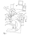
- FIG. 1 The structure of a microscope, in this case an incident light microscope, is shown schematically in FIG. 1 .
- the microscope shown essentially consists of two optical systems, an objective 1 and an eyepiece 2, which are connected to each other by a tube 3, an illumination device 4 and an object table 5 for receiving a sample 6 to be examined and a stand 7 for holding the optical parts.
- the illumination device 4 of this incident light microscope consists of an in a lamp housing 4a arranged light source 4b, the light along the optical axis 11 of the illuminating beam path via illuminating optics 4c and apertures 4d is directed onto a reflector 12 in order to to be deflected onto the sample 6 arranged on the object table 5.
- the reflector deflecting the light beam of the illuminating beam path 12 is arranged on a reflector carrier 13 designed as a linear slide, which carries several reflectors or filters 12, depending on the selected Spectral range and contrast method can be introduced into the optical axis.
- the reflector carrier 13 is motorized via a drive 14 drivable.
- a tube lens changer 16 is arranged above the reflector carrier 13, via which a corresponding tube lens 17 can be pivoted into the optical axis 15 depending on the selected contrast method and thus the chosen reflector 12.
- the tube lens changer 16 is designed as a disk that can be pivoted about a pivot point 18.
- a beam splitter 19 is also arranged.
- the assignment of a specific tube lens 17 to a specific contrast method and thus reflector 12 takes place in such a way that accordingly a suitable lens for the selected spectral range (VIS or DUV) is selected and this one the associated for the compensation system Tube lens is assigned.
- the microscope shown is for this purpose designed so that when arranging the DUV reflector 12 by means of the reflector carrier 13 the tube lens changer automatically in the illumination beam path 16 is operated so that a DUV tube lens 17 in the optical Axis 15 of the viewing beam path arranged and thus the matching Objective is assigned.
- the reflector carrier 13 on the one hand and the tube lens changer 16 on the other hand are mechanically positively coupled to one another via a driver pin 20.
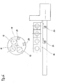
- the exact structure of the reflector carrier 13 designed as a linear slide and of the tube lens carrier 16 can be seen in FIGS. 2 to 5 .
- the tube lens changer 16 is arranged in the viewing beam path above the reflector carrier 13 and is equipped with two tube lenses 17 according to FIGS. 2 to 4 , namely a DUV tube lens 17a for the DUV spectral range and a VIS tube lens 17b for the visible VIS lens. spectral range.
- a DUV tube lens 17a for the DUV spectral range
- a VIS tube lens 17b for the visible VIS lens.
- spectral range This is a particularly advantageous embodiment, since the respective DUV tube lens 17a is calculated and designed in such a way that it forms a compensation system with various DUV lenses and can be used for all work in DUV operation. Likewise, the VIS tube lens 17b is calculated and designed in such a way that it forms a compensation system with different VIS lenses and can be used for all work in VIS operation.
- VIS tube lenses can also be used with different VIS lenses as well as different for different DUV lenses DUV tube lenses can be provided (not shown here).
- the tube lens changer 16 can be pivoted about the pivot point 18 between the end positions shown in FIGS . 2 and 3 , the twist angle in the end positions being limited by stops 21.
- the stops 21 are designed to be adjustable.
- the tube lens changer 16 has a spring 22 which prestresses the tube lens changer in the end positions against the respective stop 21 in order to hold the respective tube lens 17 securely in the correct position in the optical axis 15.
- the driver pin 20 shown schematically in FIG. 1 which mechanically forcibly couples the reflector carrier 13 on the one hand and the tube lens changer 16 on the other hand, is fixed on the reflector carrier 13 at the level of the DUV reflector 12. As can be seen from FIGS. 2 and 3 , the driver pin 20 engages in a receptacle 23 formed in the tube lens changer 16 when moving from the position of the reflector carrier 13 shown in FIG. 2 to the position shown in FIG. 3 .
- each tube lens 17 can be designed as a lens system composed of a plurality of lenses.
- FIG. 5 shows an alternative embodiment of reflector carrier 13 and tube lens changer 16.
- tube lens changer 16 is equipped with three tube lenses 17.
- the reflector carrier 13 has two driver pins 20, which can each enter a corresponding receptacle 23 of the tube lens changer 16 in order to adjust the tube lens changer 16 to the tube lens 17 corresponding to the respective reflector 12.
Landscapes
- Physics & Mathematics (AREA)
- Chemical & Material Sciences (AREA)
- Analytical Chemistry (AREA)
- General Physics & Mathematics (AREA)
- Optics & Photonics (AREA)
- Microscoopes, Condenser (AREA)
- Lens Barrels (AREA)
Applications Claiming Priority (4)
| Application Number | Priority Date | Filing Date | Title |
|---|---|---|---|
| DE10061627 | 2000-12-11 | ||
| DE10061627 | 2000-12-11 | ||
| DE10154240A DE10154240A1 (de) | 2000-12-11 | 2001-11-07 | Mikroskop |
| DE10154240 | 2001-11-07 |
Publications (3)
| Publication Number | Publication Date |
|---|---|
| EP1220005A2 true EP1220005A2 (fr) | 2002-07-03 |
| EP1220005A3 EP1220005A3 (fr) | 2003-10-22 |
| EP1220005B1 EP1220005B1 (fr) | 2005-10-19 |
Family
ID=26007930
Family Applications (1)
| Application Number | Title | Priority Date | Filing Date |
|---|---|---|---|
| EP01127889A Expired - Lifetime EP1220005B1 (fr) | 2000-12-11 | 2001-11-23 | Microscope |
Country Status (4)
| Country | Link |
|---|---|
| US (1) | US6473230B2 (fr) |
| EP (1) | EP1220005B1 (fr) |
| JP (1) | JP2002196218A (fr) |
| DE (1) | DE50107742D1 (fr) |
Cited By (1)
| Publication number | Priority date | Publication date | Assignee | Title |
|---|---|---|---|---|
| WO2004019109A1 (fr) * | 2002-08-02 | 2004-03-04 | Carl Zeiss Jena Gmbh | Dispositif optique presentant une zone de faisceau telecentrique |
Families Citing this family (6)
| Publication number | Priority date | Publication date | Assignee | Title |
|---|---|---|---|---|
| USD518840S1 (en) * | 2004-03-31 | 2006-04-11 | Swift Instruments, Inc. | Microscope with display screen |
| DE102004016433A1 (de) * | 2004-03-31 | 2005-10-20 | Zeiss Carl Jena Gmbh | Anordnung zur Veränderung der Auskopplung des Objektlichtes und/oder der Einkopplung von Licht für ein Laser-Scanning-Mikroskop |
| JP2006337643A (ja) * | 2005-06-01 | 2006-12-14 | Keyence Corp | 蛍光顕微鏡 |
| EP2204686B9 (fr) * | 2008-12-30 | 2012-11-14 | Cellavision AB | Analyseur pour l'analyse optique d'un spécimen biologique |
| DE102010039950B4 (de) * | 2010-08-30 | 2021-07-22 | Leica Microsystems Cms Gmbh | Mikroskop mit Mikro- und Makro-Objektiven |
| CN104570315B (zh) * | 2014-12-30 | 2017-06-27 | 中国科学院西安光学精密机械研究所 | 一种基于结构照明的彩色三维层析显微成像系统及方法 |
Family Cites Families (11)
| Publication number | Priority date | Publication date | Assignee | Title |
|---|---|---|---|---|
| JP3843548B2 (ja) * | 1997-08-06 | 2006-11-08 | 株式会社ニコン | 顕微鏡装置 |
| US6347009B1 (en) * | 1997-08-06 | 2002-02-12 | Nikon Corporation | Illuminating light selection device for a microscope |
| US5469299A (en) * | 1990-05-15 | 1995-11-21 | Olympus Optical Co., Ltd. | Objective lens system |
| DE4107070A1 (de) * | 1991-03-06 | 1992-09-10 | Jenoptik Jena Gmbh | Zweiteiliger, farbfehlerfreier planachromat |
| JP3647062B2 (ja) * | 1993-05-17 | 2005-05-11 | オリンパス株式会社 | 正立型顕微鏡 |
| JP3537205B2 (ja) * | 1995-02-02 | 2004-06-14 | オリンパス株式会社 | 顕微鏡装置 |
| US6366398B1 (en) * | 1995-08-17 | 2002-04-02 | Nikon Corporation | Observation apparatus |
| DE19622357B4 (de) * | 1996-06-04 | 2005-09-15 | Carl Zeiss Jena Gmbh | Vorrichtung zur Umschaltung der Betriebsarten eines Mikroskoptubus |
| US5808807A (en) * | 1996-12-04 | 1998-09-15 | Nikon Corporation | Microscope objective lens with cemented biconvex triplet |
| US6226118B1 (en) * | 1997-06-18 | 2001-05-01 | Olympus Optical Co., Ltd. | Optical microscope |
| DE19931949A1 (de) | 1999-07-09 | 2001-01-11 | Leica Microsystems | DUV-taugliches Mikroskop-Objektiv mit parfokalem IR-Fokus |
-
2001
- 2001-11-23 EP EP01127889A patent/EP1220005B1/fr not_active Expired - Lifetime
- 2001-11-23 DE DE50107742T patent/DE50107742D1/de not_active Expired - Lifetime
- 2001-11-28 JP JP2001362663A patent/JP2002196218A/ja active Pending
- 2001-12-04 US US10/004,710 patent/US6473230B2/en not_active Expired - Lifetime
Cited By (2)
| Publication number | Priority date | Publication date | Assignee | Title |
|---|---|---|---|---|
| WO2004019109A1 (fr) * | 2002-08-02 | 2004-03-04 | Carl Zeiss Jena Gmbh | Dispositif optique presentant une zone de faisceau telecentrique |
| US7154679B2 (en) | 2002-08-02 | 2006-12-26 | Carl Zeiss Jena Gmbh | Optical arrangement with a telecentric beam region |
Also Published As
| Publication number | Publication date |
|---|---|
| EP1220005B1 (fr) | 2005-10-19 |
| US6473230B2 (en) | 2002-10-29 |
| JP2002196218A (ja) | 2002-07-12 |
| US20020135870A1 (en) | 2002-09-26 |
| DE50107742D1 (de) | 2006-03-02 |
| EP1220005A3 (fr) | 2003-10-22 |
Similar Documents
| Publication | Publication Date | Title |
|---|---|---|
| DE69116818T2 (de) | Mikroskop mit einer Schärfeneinstelleinrichtung | |
| DE3442218C2 (fr) | ||
| AT399232B (de) | Mikroskop mit bildhelligkeitsabgleich | |
| DE69317103T2 (de) | Beleuchtungssystem zur Inspektion von Kontaktlinsen | |
| DE19721112B4 (de) | Autofokussierverfahren | |
| DE2946927A1 (de) | Automatische durchlichtbeleuchtung fuer mikroskope | |
| WO1999060437A1 (fr) | Systeme d'eclairage pour stereomicroscope | |
| EP1533640A2 (fr) | Microsope à fluorescence stéréo pour l'éclairage incident | |
| DE3443728C2 (de) | Mikroskop-Photometer | |
| DE3113843C2 (de) | Durchlicht-Beleuchtungssystem für Mikroskope | |
| EP1220005B1 (fr) | Microscope | |
| KR20020001892A (ko) | 현미경유닛 | |
| DE3853475T2 (de) | Konzept und umwandlungssatz eines standardmikroskops in ein mikroskop mit gemeinsamem brennpunkt und epi-beleuchtung mit einzelöffnung. | |
| DE102015211375B4 (de) | Infrarot-Mikroskop und Vergrößerungsgruppe für ein Infrarot-Mikroskop | |
| DE3700965C2 (fr) | ||
| DE4404286A1 (de) | Fluoreszenzeinrichtung für Invers-Mikroskope | |
| DE2407270B1 (de) | Vergleichsmikroskop | |
| DE10154240A1 (de) | Mikroskop | |
| DE3740737A1 (de) | Mikroskopeinrichtung | |
| DE3033758C2 (fr) | ||
| CH656011A5 (de) | Auflichtilluminator fuer hell- und dunkelfeldbeleuchtung. | |
| DE10257521B4 (de) | Auflichtmikroskop | |
| DE3443727C2 (de) | Mikroskopphotometer für Bildscanning und Wellenlängenscanning | |
| DE102005059650B4 (de) | Vorrichtung zur Montage für mehrere Laser und Mikroskop | |
| DE102024128340B3 (de) | Scanner-Modul zur Verwendung mit einem Mikroskop, sowie Mikroskop mit einem Scanner-Modul |
Legal Events
| Date | Code | Title | Description |
|---|---|---|---|
| PUAI | Public reference made under article 153(3) epc to a published international application that has entered the european phase |
Free format text: ORIGINAL CODE: 0009012 |
|
| AK | Designated contracting states |
Kind code of ref document: A2 Designated state(s): AT BE CH CY DE DK ES FI FR GB GR IE IT LI LU MC NL PT SE TR |
|
| AX | Request for extension of the european patent |
Free format text: AL;LT;LV;MK;RO;SI |
|
| PUAL | Search report despatched |
Free format text: ORIGINAL CODE: 0009013 |
|
| AK | Designated contracting states |
Kind code of ref document: A3 Designated state(s): AT BE CH CY DE DK ES FI FR GB GR IE IT LI LU MC NL PT SE TR |
|
| AX | Request for extension of the european patent |
Extension state: AL LT LV MK RO SI |
|
| RIC1 | Information provided on ipc code assigned before grant |
Ipc: 7G 02B 21/24 B Ipc: 7G 02B 21/16 B Ipc: 7G 02B 21/18 A |
|
| 17P | Request for examination filed |
Effective date: 20040408 |
|
| AKX | Designation fees paid |
Designated state(s): DE FR GB |
|
| 17Q | First examination report despatched |
Effective date: 20040727 |
|
| GRAP | Despatch of communication of intention to grant a patent |
Free format text: ORIGINAL CODE: EPIDOSNIGR1 |
|
| GRAS | Grant fee paid |
Free format text: ORIGINAL CODE: EPIDOSNIGR3 |
|
| GRAA | (expected) grant |
Free format text: ORIGINAL CODE: 0009210 |
|
| AK | Designated contracting states |
Kind code of ref document: B1 Designated state(s): DE FR GB |
|
| REG | Reference to a national code |
Ref country code: GB Ref legal event code: FG4D Free format text: NOT ENGLISH |
|
| GBT | Gb: translation of ep patent filed (gb section 77(6)(a)/1977) |
Effective date: 20051207 |
|
| RAP2 | Party data changed (patent owner data changed or rights of a patent transferred) |
Owner name: LEICA MICROSYSTEMS CMS GMBH |
|
| REF | Corresponds to: |
Ref document number: 50107742 Country of ref document: DE Date of ref document: 20060302 Kind code of ref document: P |
|
| ET | Fr: translation filed | ||
| PLBE | No opposition filed within time limit |
Free format text: ORIGINAL CODE: 0009261 |
|
| STAA | Information on the status of an ep patent application or granted ep patent |
Free format text: STATUS: NO OPPOSITION FILED WITHIN TIME LIMIT |
|
| 26N | No opposition filed |
Effective date: 20060720 |
|
| REG | Reference to a national code |
Ref country code: FR Ref legal event code: PLFP Year of fee payment: 15 |
|
| REG | Reference to a national code |
Ref country code: FR Ref legal event code: PLFP Year of fee payment: 16 |
|
| REG | Reference to a national code |
Ref country code: FR Ref legal event code: PLFP Year of fee payment: 17 |
|
| PGFP | Annual fee paid to national office [announced via postgrant information from national office to epo] |
Ref country code: GB Payment date: 20201126 Year of fee payment: 20 Ref country code: FR Payment date: 20201126 Year of fee payment: 20 |
|
| PGFP | Annual fee paid to national office [announced via postgrant information from national office to epo] |
Ref country code: DE Payment date: 20210128 Year of fee payment: 20 |
|
| REG | Reference to a national code |
Ref country code: DE Ref legal event code: R071 Ref document number: 50107742 Country of ref document: DE |
|
| REG | Reference to a national code |
Ref country code: GB Ref legal event code: PE20 Expiry date: 20211122 |
|
| PG25 | Lapsed in a contracting state [announced via postgrant information from national office to epo] |
Ref country code: GB Free format text: LAPSE BECAUSE OF EXPIRATION OF PROTECTION Effective date: 20211122 |