EP1220035A2 - Membranabdeckung - Google Patents
Membranabdeckung Download PDFInfo
- Publication number
- EP1220035A2 EP1220035A2 EP01310899A EP01310899A EP1220035A2 EP 1220035 A2 EP1220035 A2 EP 1220035A2 EP 01310899 A EP01310899 A EP 01310899A EP 01310899 A EP01310899 A EP 01310899A EP 1220035 A2 EP1220035 A2 EP 1220035A2
- Authority
- EP
- European Patent Office
- Prior art keywords
- mask
- resin layer
- pellicle
- layer
- adhering
- Prior art date
- Legal status (The legal status is an assumption and is not a legal conclusion. Google has not performed a legal analysis and makes no representation as to the accuracy of the status listed.)
- Withdrawn
Links
Images

Classifications
-
- G—PHYSICS
- G03—PHOTOGRAPHY; CINEMATOGRAPHY; ANALOGOUS TECHNIQUES USING WAVES OTHER THAN OPTICAL WAVES; ELECTROGRAPHY; HOLOGRAPHY
- G03F—PHOTOMECHANICAL PRODUCTION OF TEXTURED OR PATTERNED SURFACES, e.g. FOR PRINTING, FOR PROCESSING OF SEMICONDUCTOR DEVICES; MATERIALS THEREFOR; ORIGINALS THEREFOR; APPARATUS SPECIALLY ADAPTED THEREFOR
- G03F1/00—Originals for photomechanical production of textured or patterned surfaces, e.g., masks, photo-masks, reticles; Mask blanks or pellicles therefor; Containers specially adapted therefor; Preparation thereof
- G03F1/62—Pellicles, e.g. pellicle assemblies, e.g. having membrane on support frame; Preparation thereof
-
- G—PHYSICS
- G03—PHOTOGRAPHY; CINEMATOGRAPHY; ANALOGOUS TECHNIQUES USING WAVES OTHER THAN OPTICAL WAVES; ELECTROGRAPHY; HOLOGRAPHY
- G03F—PHOTOMECHANICAL PRODUCTION OF TEXTURED OR PATTERNED SURFACES, e.g. FOR PRINTING, FOR PROCESSING OF SEMICONDUCTOR DEVICES; MATERIALS THEREFOR; ORIGINALS THEREFOR; APPARATUS SPECIALLY ADAPTED THEREFOR
- G03F1/00—Originals for photomechanical production of textured or patterned surfaces, e.g., masks, photo-masks, reticles; Mask blanks or pellicles therefor; Containers specially adapted therefor; Preparation thereof
- G03F1/62—Pellicles, e.g. pellicle assemblies, e.g. having membrane on support frame; Preparation thereof
- G03F1/64—Pellicles, e.g. pellicle assemblies, e.g. having membrane on support frame; Preparation thereof characterised by the frames, e.g. structure or material, including bonding means therefor
-
- Y—GENERAL TAGGING OF NEW TECHNOLOGICAL DEVELOPMENTS; GENERAL TAGGING OF CROSS-SECTIONAL TECHNOLOGIES SPANNING OVER SEVERAL SECTIONS OF THE IPC; TECHNICAL SUBJECTS COVERED BY FORMER USPC CROSS-REFERENCE ART COLLECTIONS [XRACs] AND DIGESTS
- Y10—TECHNICAL SUBJECTS COVERED BY FORMER USPC
- Y10T—TECHNICAL SUBJECTS COVERED BY FORMER US CLASSIFICATION
- Y10T428/00—Stock material or miscellaneous articles
- Y10T428/24—Structurally defined web or sheet [e.g., overall dimension, etc.]
- Y10T428/24942—Structurally defined web or sheet [e.g., overall dimension, etc.] including components having same physical characteristic in differing degree
- Y10T428/2495—Thickness [relative or absolute]
- Y10T428/24959—Thickness [relative or absolute] of adhesive layers
-
- Y—GENERAL TAGGING OF NEW TECHNOLOGICAL DEVELOPMENTS; GENERAL TAGGING OF CROSS-SECTIONAL TECHNOLOGIES SPANNING OVER SEVERAL SECTIONS OF THE IPC; TECHNICAL SUBJECTS COVERED BY FORMER USPC CROSS-REFERENCE ART COLLECTIONS [XRACs] AND DIGESTS
- Y10—TECHNICAL SUBJECTS COVERED BY FORMER USPC
- Y10T—TECHNICAL SUBJECTS COVERED BY FORMER US CLASSIFICATION
- Y10T428/00—Stock material or miscellaneous articles
- Y10T428/24—Structurally defined web or sheet [e.g., overall dimension, etc.]
- Y10T428/24942—Structurally defined web or sheet [e.g., overall dimension, etc.] including components having same physical characteristic in differing degree
- Y10T428/24983—Hardness
Definitions
- the present invention relates to a pellicle used in a step of photolithography in the production of integrated circuits for the purpose of preventing dust and dirt from adhering onto the mask or the reticle (hereinafter simply referred to as mask and the like). More specifically, the invention relates to a pellicle of which an adhesive resin layer for mounting the pellicle on the mask is formed of a hard resin layer and a soft resin layer.
- a transparent pellicle film of a nitrocellulose or the like is stretched, via an adhesive layer, on an end of a pellicle frame made of aluminum or the like, and the other end of the pellicle frame is adhered with an adhesive (mask-adhering) layer onto the pattern-forming surface of the mask or the like, so that the pellicle will not be removed from the mask or the like during the handling.
- the mask-adhering agent exhibits a too strong adhering force, therefore, the mask is damaged due to the application of an excessive force at the time of peeling the pellicle off the mask and the like or the mask-adhering agent remains on the mask after it has been peeled off. As a result, the semiconductor devices could become defective or the yield of production decreases.
- the step of photolithography furthermore, exposure to light is effected not only where flat surfaces of the mask and of the pellicle film are maintained in a horizontal direction but also where flat surfaces of the mask and of the pellicle film are maintained in a vertical direction.
- the layer of the mask-adhering layer hangs down due to its own weight in the case of the mask-adhering agent taught in the above Japanese Unexamined Patent Publication (Kokai) No. 282640/1998 spoiling the flatness of the mask.
- a pellicle comprising a pellicle film, a pellicle frame supporting the pellicle film, and an adhesive resin layer provided on the surface of the pellicle frame on the side opposite to the surface supporting the pellicle film, wherein the adhesive resin layer is formed of a combination of a hard resin layer and a soft resin layer.
- the adhesive resin layer has such a layer structure that the soft resin layer is located on the side of the pellicle frame and the hard resin layer is located on the soft resin layer. With this layer structure, the pellicle is mounted on the mask via the hard resin layer.
- the hard resin layer has a thickness which is from 5 to 30% of the thickness of the adhesive resin layer
- the soft resin layer has a thickness which is from 95 to 70% of the thickness of the adhesive resin layer.
- the soft resin layer can be sandwiched between the two hard resin layers. In this case, the hard resin layer comes in contact with both the pellicle frame and the mask.
- the adhesive resin layer can have such a layer structure that both the soft resin layer and the hard resin layer come in contact with the pellicle frame. With this layer structure, both the soft resin layer and the hard resin layer come in contact with the mask that is mounted.
- the hard resin layer is disposed on the lower side of the soft resin layer.
- the soft resin layer is disposed between the two hard resin layers.
- the width of contact between the hard resin layer and the mask that is mounted is from 10 to 30% of the width of contact between the adhesive resin layer and the mask that is mounted.
- the present inventors In studying a mask mounting a pellicle, the present inventors have discovered the fact that the hardness of the adhesive resin layer for securing the pellicle frame to the mask plays an important role for maintaining the flatness of the mask. It is desired that the adhesive resin layer (hereinafter often called mask-adhering layer) exhibits a suitable adhering force on the interface to the mask.
- the adhesive resin layer hereinafter often called mask-adhering layer
- the mask-adhering layer between the mask and the pellicle frame is formed of a hard resin
- the mask and the mask-adhering layer are secured together.
- the interface is flat between the pellicle frame and the mask-adhering layer (hard resin)
- the mask maintains flatness.
- the interface has a wide area, however, it becomes difficult to maintain the whole interface completely flat; i.e., the mask is distorted tracing the mask-adhering layer (hard resin) and loses flatness.
- the mask-adhering layer which is hard is mounted on the mask, a gap is formed between the mask-adhering layer and the mask or the pellicle frame, permitting dust and dirt to enter.
- the mask-adhering layer that is formed of a soft resin absorbs the load of the mask and of the pellicle frame imparting such an adhering force that permits peeling from the mask and the pellicle frame.
- a mask-adhering layer soft resin
- the layer of the mask-adhering layer hangs down due to its own weight. If there occurs an interfacial peeling, therefore, the mask-adhering layer deviates down.
- undesired stress acts upon the mask, whereby the mask is distorted to spoil the flatness of the mask.
- the mask-adhering layer according to the present invention is formed of a hard resin layer and a soft resin layer, so that the mask-adhering layer (adhesive resin layer) interposed between the pellicle frame and the mask will not affect the mask even when the mask mounting the pellicle is placed in a horizontal state or in a vertical state.
- the mask needs softly trace the hard resin layer owing to the soft resin layer yet the deformation of the soft resin layer due to its own weight is suppressed by the hard resin layer.
- deviation of the pellicle of when it is maintained in the vertical direction is suppressed by the hard resin layer, minimizing the effect of the mask-adhering layer upon the mask, preventing the mask from losing flatness.
- Flatness of the mask is expressed by a displacement ( ⁇ m) of a Z-axis perpendicular to an XY-plane of the mask defined by an X-axis and a Y-axis. The value becomes 0 when the mask is completely flat.
- a range of flatness of the mask that does not impose problem in practice is about 2 ⁇ m in average in a region surrounded by a square pellicle having a side of 5 inches, and is about 5 ⁇ m in average in a region surrounded by a square pellicle having a side of 6 inches.
- Use of the pellicle of the present invention makes it possible to obtain flatness satisfying the above values.
- the hard resin has a hardness of not smaller than 170 gf and, particularly, in a range of from 200 to 240 gf and that the soft resin has a hardness of not larger than 100 gf and, particularly, in a range of from 40 to 80 gf.
- the hardness can be measured by using a rubber hardness meter GS-70 (JIA A TYPE).
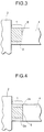
- the adhesive resin layer has a structure as shown in Figs. 1 to 4, wherein reference numeral 1 denotes an adhesive resin layer (mask-adhering layer), 2 denotes a mask, 3 denotes a hard resin layer, 4 denotes a pellicle frame and reference numeral 5 denotes a soft resin layer.
- the hard resin layer 3 in the mask-adhering layer 1 is disposed on the side of the mask 2, and the soft resin layer 5 in the mask-adhering layer 1 is disposed on the side of the pellicle frame 4.
- the hard resin layer 3 has a small thickness and the soft resin layer 5 has a large thickness.
- the mask-adhering layer 1 includes a soft resin layer 5 and two hard resin layers 3a, 3b, the soft resin layer 5 being sandwiched between the two hard resin layers 3a and 3b. Further, one (3a) of the two hard resin layers 3a, 3b is in contact with the pellicle frame 4 and the other one (3b) is in contact with the mask 2. Like in Fig. 1, further, the hard resin layers 3a and 3b have small thicknesses and the soft resin layer 5 has a large thickness.
- the layer structures shown in Figs. 3 and 4 are desired when the surface of the mask 2 (surface of the pellicle film) is maintained in the vertical direction.
- both the hard resin layer 3 (3a, 3b) and the soft resin layer 5 are in contact with the pellicle frame 4 and with the mask 2.
- the mask-adhering layer 1 is formed by one hard resin layer 3 and one soft resin layer 5.
- the soft resin layer 5 is sandwiched between the two hard resin layers 3a and 3b.
- the hard resin layer 3 (3a, 3b) has a small thickness and the soft resin layer 5 has a large thickness.
- a thin layer 3 of a hard resin is provided at least under the thick layer 5 of the soft resin. That is, when the pellicle is maintained in the vertical direction, the hard resin layer 3 is positioned at least under the soft resin layer 5 in order to suppress the deformation or downward deviation of the soft resin layer 5 due to its own weight by utilizing the hard resin layer.
- the layer structure of the adhesive resin layer (mask-adhering layer) depending upon the position of the pellicle frame, as a matter of course.
- the mask-adhering layer formed on the end surface of a portion of the pellicle frame extending in the horizontal direction may have a layer structure as shown in Fig. 3 or 4
- the mask-adhering layer formed on the end surface of a portion of the pellicle frame extending in the vertical direction may have a layer structure as shown in Fig. 1 or 2.
- the mask-adhering layer 1 itself has a thickness of usually from about 200 microns ( ⁇ m) to about 2000 microns ( ⁇ m) and in which the hard resin layer 3 has a thickness in a range of from 5 to 30% and, particularly, from 5 to 25% and the soft resin layer 5 has a thickness in a range of from 95 to 70% and, particularly, from 95 to 75%.
- the width (corresponding to the width of adhesion) for providing the mask-adhering layer 1 is usually from 1200 ⁇ m to 5000 ⁇ m. It is also allowable to change the ratio of the width (adhering width) of the hard resin layer 3 and the width (adhering width) of the soft resin layer 5. Here, however, it is desired that the width of the hard resin layer 3 is from 10 to 30% of the whole width (mask-adhering layer 1) and the width of the soft resin layer 5 is from 90 to 70% of the whole width.
- the embodiment of Fig. 3 is desired.
- the thin layer 3 of the hard resin exhibits an enhanced effect when it is formed on the lower side so as to support the pellicle.
- the thin lay 3 of the hard resin may be provided on the side of a space defined by the pellicle and the mask and on the outside of the thick layer 5 of the soft resin.
- the thickness of the layer of the hard resin is from 10 to 30% of the whole thickness of the mask-adhering layer, and the layer of the soft resin is from 90 to 70% of the whole thickness of the mask-adhering layer.
- the ratios of the thickness and the width of the hard resin layer become greater than the above-mentioned ranges, the distortion of the mask or of the pellicle frame caused by the hard resin layer is relaxed by the soft resin layer to a decreased extent. As a result, the adhering strength becomes irregular.
- the hard resin used in the present invention is an adhesive agent such as acrylic, rubber, polybutene or polyurethane, which can be used alone or in a combination of two or more kinds.
- the hard resin exhibits an adhering force of from 50 to 700 g/cm and, particularly, from 220 to 700 g/cm as measured in compliance with the adhering force testing method stipulated under JIS Z-0237.
- the soft resin used in the present invention is an adhesive agent such as acrylic, rubber, polybutene or polyurethane, which can be used alone or in a combination of two or more kinds. It is desired that the soft resin exhibits an adhering force of from 100 to 1200 g/cm and, particularly, from 350 to 600 g/cm as measured in compliance with the adhering force testing method stipulated under JIS Z-0237.
- the hardnesses and adhering forces of the adhesive agents used as the hard resin and the soft resin for forming the mask-adhering layer can be adjusted to desired values by adjusting the molecular weights of resins, amounts of functional groups and compositions thereof.
- the mask-adhering layer can be formed by directly applying the soft resin and the hard resin as mask-adhering agents onto the pellicle frame.
- the mask-adhering layer is laminated in parallel with the end surface of the pellicle frame by successively applying the resins.
- the mask-adhering layer is laminated vertically to the end surface of the pellicle frame by simultaneously or separately applying the resins thereon.
- the resins can be applied by any known application means, such as spray-application method, brush-application method, roller-coating method, or spread-application method.
- the spray-application method is employed, the liquid droplets put on the frame are drawn by using a jig and is evenly applied thereon followed by drying to thereby form the mask-adhering layer.
- the pellicle frame may be made of a metal such as aluminum, aluminum alloy or stainless steel, or may be made of a synthetic resin or ceramics.
- the weight of the pellicle frame is not larger than 100 g and is, particularly, in a range of from 10 to 30 g from the above-mentioned relationship between the resin layer and the adhering force.
- the pellicle of the present invention is such that the pellicle film is stretched on one side of the pellicle frame via the adhesive resin layer, and the adhesive resin layer (mask-adhering layer) comprising the hard resin and the soft resin is provided on the other side so as to be mounted on the mask.
- any known pellicle film can be used for the pellicle of the present invention.
- the pellicle film may be formed of nitrocellulose, cellulose propionate or fluorine-contained material.
- the soft resins and hard resins that are used are hot-melt resins (having melting points of from 180 to 200°C). Wax, ethylene-vinyl acetate copolymer and resin are adjusted for their compositions, and are used as soft resins and hard resins.
- a mask-adhering layer was formed on an aluminum frame as shown in Fig. 1 in a manner that the soft resin layer 5 possessed a hardness of from 40 to 100 gf and a thickness of from 75 to 95% and that the hard resin layer 3 possessed a hardness of from 170 to 240 gf and a thickness of from 5 to 25%.
- the frame on which the mask-adhering layer was formed as described above was stuck to the mask in a horizontal state with a sticking load of 30 kg for 3 minutes.
- the mask in a stuck state was preserved for a month to measure the deformation of the mask-adhering layer and flatness of the mask (Tables 1 and 2).
- the flatness of the mask could be maintained after being stuck, and the mask-adhering layer was not deformed.
- the frame could be easily peeled off since it was mounted on the mask via the hard resin layer, and the flatness could be maintained even after the peeling.
- Example 1 The frame on which the mask-adhering layer was formed under the conditions lying outside the scope of Example 1 was measured in the same manner as in Example 1 [Table 1 (1, 3, 7, 11) and Table 2 (1, 3, 7, 11)]. As a result, problems occurred as shown in Tables 1 and 2.
- a mask-adhering layer 1 was formed on an aluminum frame to constitute the layer structure as shown in Fig. 1 in a manner that the soft resin layer 5 possessed a hardness of from 40 to 100 gf and a thickness of from 75 to 95% and that the hard resin layers 3a and 3b possessed hardnesses of from 170 to 240 gf and thicknesses of from 5 to 25%.
- the frame on which the mask-adhering layer was formed as described above was stuck to the mask in a horizontal state with a sticking load of 30 kg for 3 minutes.
- the mask in a stuck state was preserved for a month to measure the deformation of the mask-adhering layer and flatness of the mask (Tables 3 and 4).
- the frame was then peeled off the mask to measure the peeling property and flatness of the mask after peeling (Tables 3 and 4).
- the flatness of the mask could be maintained after being stuck, and the mask-adhering layer was not deformed.
- the frame could be easily peeled off since it was mounted on the mask via the mask-adhering layer of a combination of the hard resin layer and the soft resin layer, and the flatness could be maintained even after the peeling.
- Example 2 The frame on which the mask-adhering layer was formed under the conditions lying outside the scope of Example 2 was measured in the same manner as in Example 2 [Table 3 (1, 3, 7, 11) and Table 4 (1, 3, 7, 11)]. As a result, problems occurred as shown in Tables 3 and 4.
- a mask-adhering layer was formed on an aluminum frame to constitute the layer structure as shown in Fig. 3 in a manner that the soft resin layer 5 possessed a hardness of from 40 to 100 gf and a thickness of from 70 to 90% and that the hard resin layer 3 possessed a hardness of from 170 to 240 gf and a thickness of from 10 to 30%.
- the frame on which the mask-adhering layer was formed as described above was stuck to the mask in a vertical state with a sticking load of 30 kg for 3 minutes.
- the flatness of the mask could be maintained after being stuck, and the mask-adhering layer was not deformed.
- the frame could be easily peeled off since it was mounted on the mask via the mask-adhering layer of a combination of the hard resin layer and the soft resin layer, and the flatness could be maintained even after the peeling.
- Example 3 The frame on which the mask-adhering layer was formed under the conditions lying outside the scope of Example 3 was measured in the same manner as in Example 3 [Table 5 (1, 3, 7, 11) and Table 6 (1, 3, 7, 11)]. As a result, problems occurred as shown in Tables 5 and 6.
- a mask-adhering layer was formed on an aluminum frame to constitute the layer structure as shown in Fig. 4 in a manner that the soft resin layer 5 possessed a hardness of from 40 to 100 gf and a thickness of from 70 to 90% and that the hard resin layers 3a and 3b possessed hardnesses of from 170 to 240 gf and thicknesses of from 10 to 30%.
- the frame on which the mask-adhering layer was formed as described above was stuck to the mask in a vertical state with a sticking load of 30 kg for 3 minutes.
- the mask in a stuck state was preserved for a month to measure the deformation of the mask-adhering layer and flatness of the mask (Tables 7 and 8).
- the frame was then peeled off the mask to measure the peeling property and flatness of the mask after peeling (Tables 7 and 8).
- the flatness of the mask could be maintained after being stuck, and the mask-adhering layer was not deformed.
- the frame could be easily peeled off since it was mounted on the mask via the mask-adhering layer of a combination of the hard resin layer and the soft resin layer, and the flatness could be maintained even after the peeling.
- Example 4 The frame on which the mask-adhering layer was formed under the conditions lying outside the scope of Example 4 was measured in the same manner as in Example 4 [Table 7 (1, 3, 7, 11) and Table 8 (1, 3, 7, 11)]. As a result, problems occurred as shown in Tables 7 and 8.
- the mask-adhering layer for mounting the pellicle on the mask is formed of a combination of a hard resin layer and a soft resin layer, the hard resin having a hardness of not smaller than 170 gf and the soft resin having a hardness of not larger than 100 gf.
- the mask In mounting the pellicle on the mask or in peeling the pellicle off the mask, therefore, the mask is not damaged and the adhesive does not remain on the mask.
- the mask maintains flatness even when the surfaces of the mask and of the pellicle film are held not only in the horizontal direction but also in the vertical direction.
Landscapes
- Physics & Mathematics (AREA)
- General Physics & Mathematics (AREA)
- Preparing Plates And Mask In Photomechanical Process (AREA)
- Laminated Bodies (AREA)
Applications Claiming Priority (2)
| Application Number | Priority Date | Filing Date | Title |
|---|---|---|---|
| JP2000399447 | 2000-12-27 | ||
| JP2000399447 | 2000-12-27 |
Publications (2)
| Publication Number | Publication Date |
|---|---|
| EP1220035A2 true EP1220035A2 (de) | 2002-07-03 |
| EP1220035A3 EP1220035A3 (de) | 2002-09-11 |
Family
ID=18864225
Family Applications (1)
| Application Number | Title | Priority Date | Filing Date |
|---|---|---|---|
| EP01310899A Withdrawn EP1220035A3 (de) | 2000-12-27 | 2001-12-27 | Membranabdeckung |
Country Status (5)
| Country | Link |
|---|---|
| US (1) | US6713136B2 (de) |
| EP (1) | EP1220035A3 (de) |
| KR (1) | KR20020053747A (de) |
| CN (1) | CN1198316C (de) |
| TW (1) | TW535031B (de) |
Cited By (1)
| Publication number | Priority date | Publication date | Assignee | Title |
|---|---|---|---|---|
| EP2120093A1 (de) * | 2008-05-14 | 2009-11-18 | Shin-Etsu Chemical Co., Ltd. | Schutzmembran zur Verwendung in der Halbleiter-Lithographie |
Families Citing this family (11)
| Publication number | Priority date | Publication date | Assignee | Title |
|---|---|---|---|---|
| US7316869B2 (en) * | 2003-08-26 | 2008-01-08 | Intel Corporation | Mounting a pellicle to a frame |
| US7264853B2 (en) * | 2003-08-26 | 2007-09-04 | Intel Corporation | Attaching a pellicle frame to a reticle |
| US20050202252A1 (en) * | 2004-03-12 | 2005-09-15 | Alexander Tregub | Use of alternative polymer materials for "soft" polymer pellicles |
| US7314667B2 (en) * | 2004-03-12 | 2008-01-01 | Intel Corporation | Process to optimize properties of polymer pellicles and resist for lithography applications |
| US8070840B2 (en) | 2005-04-22 | 2011-12-06 | Shell Oil Company | Treatment of gas from an in situ conversion process |
| KR20060116152A (ko) * | 2005-05-09 | 2006-11-14 | 미쓰이 가가쿠 가부시키가이샤 | 오염이 적은 펠리클 |
| US20060269847A1 (en) * | 2005-05-25 | 2006-11-30 | International Business Machines Corporaton | Binding of hard pellicle structure to mask blank and method |
| JP4931717B2 (ja) * | 2007-07-19 | 2012-05-16 | 信越化学工業株式会社 | リソグラフィー用ペリクルの製造方法 |
| KR101280676B1 (ko) * | 2009-07-16 | 2013-07-01 | 미쓰이 가가쿠 가부시키가이샤 | 펠리클 프레임 및 그것을 포함하는 펠리클 |
| KR102242562B1 (ko) | 2014-09-04 | 2021-04-20 | 삼성전자주식회사 | 극자외선(euv) 마스크 보호장치 및 그 보호장치를 포함한 euv 노광 장치 |
| US9880462B2 (en) | 2014-11-28 | 2018-01-30 | Samsung Electronics Co., Ltd. | Pellicle and exposure mask including the same |
Family Cites Families (4)
| Publication number | Priority date | Publication date | Assignee | Title |
|---|---|---|---|---|
| JPS6075835A (ja) * | 1983-10-03 | 1985-04-30 | Hitachi Ltd | ペリクル |
| JP2714450B2 (ja) * | 1989-08-10 | 1998-02-16 | ダイセル化学工業株式会社 | 防塵膜 |
| DE69130280T2 (de) * | 1990-10-16 | 1999-04-08 | Mitsui Chemicals, Inc., Tokio/Tokyo | Verwendung eines hochlichtdurchlässigen staubschützenden Films, Verfahren zu dessen Herstellung und staubschützendes Element |
| JPH0922111A (ja) * | 1995-07-05 | 1997-01-21 | Shin Etsu Chem Co Ltd | ペリクル |
-
2001
- 2001-12-20 CN CNB011446080A patent/CN1198316C/zh not_active Expired - Fee Related
- 2001-12-25 TW TW090132161A patent/TW535031B/zh not_active IP Right Cessation
- 2001-12-26 US US10/025,562 patent/US6713136B2/en not_active Expired - Lifetime
- 2001-12-26 KR KR1020010084948A patent/KR20020053747A/ko not_active Ceased
- 2001-12-27 EP EP01310899A patent/EP1220035A3/de not_active Withdrawn
Cited By (1)
| Publication number | Priority date | Publication date | Assignee | Title |
|---|---|---|---|---|
| EP2120093A1 (de) * | 2008-05-14 | 2009-11-18 | Shin-Etsu Chemical Co., Ltd. | Schutzmembran zur Verwendung in der Halbleiter-Lithographie |
Also Published As
| Publication number | Publication date |
|---|---|
| US20020136965A1 (en) | 2002-09-26 |
| CN1361547A (zh) | 2002-07-31 |
| US6713136B2 (en) | 2004-03-30 |
| KR20020053747A (ko) | 2002-07-05 |
| CN1198316C (zh) | 2005-04-20 |
| TW535031B (en) | 2003-06-01 |
| EP1220035A3 (de) | 2002-09-11 |
Similar Documents
| Publication | Publication Date | Title |
|---|---|---|
| EP0752621B1 (de) | Rahmengestützte Membranabdeckung zum Schutz einer Photomaske | |
| US6713136B2 (en) | Pellicle | |
| US20080248407A1 (en) | Pellicle | |
| US20090191470A1 (en) | Pellicle frame | |
| CN101144975A (zh) | 光蚀刻用防护膜组件 | |
| US20090023082A1 (en) | Pellicle frame | |
| CN102141727A (zh) | 光刻用防尘薄膜组件及其制造方法 | |
| EP2034360B1 (de) | Membranrahmen | |
| EP2998792B1 (de) | Membranrahmen und membran | |
| JP4951051B2 (ja) | ペリクルフレーム及びペリクル | |
| EP0304211B1 (de) | Staubgeschützter Film | |
| KR101166460B1 (ko) | 펠리클 프레임, 및 이 프레임을 사용한 포토리소그래피용 펠리클 | |
| JP4043232B2 (ja) | 大型ペリクル | |
| JP3597166B2 (ja) | ペリクル | |
| US6303196B1 (en) | Pellicle | |
| JP2006163035A (ja) | 大型ペリクル、ペリクル搬送方法、ペリクルケース及びペリクル移載装置 | |
| US8541149B2 (en) | Method of adhering lithographic pellicle and adhering apparatus therefor | |
| JP5619436B2 (ja) | 大型ペリクル用枠体、及び大型ペリクル | |
| JP4601204B2 (ja) | ペリクル用枠体 | |
| JP2001201845A (ja) | 大型ペリクル | |
| JP2939193B2 (ja) | 防塵膜 | |
| JP2001228600A (ja) | ペリクルフレーム、これを用いたペリクル及びペリクルの製造方法 |
Legal Events
| Date | Code | Title | Description |
|---|---|---|---|
| PUAI | Public reference made under article 153(3) epc to a published international application that has entered the european phase |
Free format text: ORIGINAL CODE: 0009012 |
|
| AK | Designated contracting states |
Kind code of ref document: A2 Designated state(s): AT BE CH CY DE DK ES FI FR GB GR IE IT LI LU MC NL PT SE TR |
|
| AX | Request for extension of the european patent |
Free format text: AL;LT;LV;MK;RO;SI |
|
| PUAL | Search report despatched |
Free format text: ORIGINAL CODE: 0009013 |
|
| AK | Designated contracting states |
Kind code of ref document: A3 Designated state(s): AT BE CH CY DE DK ES FI FR GB GR IE IT LI LU MC NL PT SE TR |
|
| AX | Request for extension of the european patent |
Free format text: AL;LT;LV;MK;RO;SI |
|
| 17P | Request for examination filed |
Effective date: 20021112 |
|
| AKX | Designation fees paid |
Designated state(s): DE FR GB |
|
| RAP1 | Party data changed (applicant data changed or rights of an application transferred) |
Owner name: MITSUI CHEMICALS, INC. |
|
| GRAP | Despatch of communication of intention to grant a patent |
Free format text: ORIGINAL CODE: EPIDOSNIGR1 |
|
| STAA | Information on the status of an ep patent application or granted ep patent |
Free format text: STATUS: THE APPLICATION IS DEEMED TO BE WITHDRAWN |
|
| 18D | Application deemed to be withdrawn |
Effective date: 20071221 |