EP1220165A2 - Appareil pour détecter la fluorescence ultra-violet et méthode de détection correspondante - Google Patents
Appareil pour détecter la fluorescence ultra-violet et méthode de détection correspondante Download PDFInfo
- Publication number
- EP1220165A2 EP1220165A2 EP01129446A EP01129446A EP1220165A2 EP 1220165 A2 EP1220165 A2 EP 1220165A2 EP 01129446 A EP01129446 A EP 01129446A EP 01129446 A EP01129446 A EP 01129446A EP 1220165 A2 EP1220165 A2 EP 1220165A2
- Authority
- EP
- European Patent Office
- Prior art keywords
- ultraviolet ray
- light
- filter
- detecting apparatus
- fluorescence
- Prior art date
- Legal status (The legal status is an assumption and is not a legal conclusion. Google has not performed a legal analysis and makes no representation as to the accuracy of the status listed.)
- Withdrawn
Links
- 238000000034 method Methods 0.000 title claims abstract description 15
- 238000005192 partition Methods 0.000 claims abstract description 14
- 238000000638 solvent extraction Methods 0.000 claims abstract description 3
- 238000001514 detection method Methods 0.000 claims description 25
- 238000012545 processing Methods 0.000 claims description 14
- 238000005070 sampling Methods 0.000 claims description 14
- 230000035945 sensitivity Effects 0.000 claims description 7
- 230000005540 biological transmission Effects 0.000 claims description 3
- 239000011521 glass Substances 0.000 claims description 3
- 230000003287 optical effect Effects 0.000 description 10
- 238000010586 diagram Methods 0.000 description 9
- 239000000463 material Substances 0.000 description 6
- 238000001917 fluorescence detection Methods 0.000 description 3
- 238000012544 monitoring process Methods 0.000 description 3
- 230000002093 peripheral effect Effects 0.000 description 3
- 239000000758 substrate Substances 0.000 description 3
- 238000012937 correction Methods 0.000 description 2
- 238000001506 fluorescence spectroscopy Methods 0.000 description 2
- 238000007740 vapor deposition Methods 0.000 description 2
- 230000002159 abnormal effect Effects 0.000 description 1
- 230000005856 abnormality Effects 0.000 description 1
- 239000003086 colorant Substances 0.000 description 1
- 238000004891 communication Methods 0.000 description 1
- 238000012790 confirmation Methods 0.000 description 1
- 230000003247 decreasing effect Effects 0.000 description 1
- 230000000694 effects Effects 0.000 description 1
- 238000000295 emission spectrum Methods 0.000 description 1
- 230000009545 invasion Effects 0.000 description 1
- WABPQHHGFIMREM-UHFFFAOYSA-N lead(0) Chemical compound [Pb] WABPQHHGFIMREM-UHFFFAOYSA-N 0.000 description 1
- 238000004519 manufacturing process Methods 0.000 description 1
- 230000003014 reinforcing effect Effects 0.000 description 1
- 229920006395 saturated elastomer Polymers 0.000 description 1
- 230000003595 spectral effect Effects 0.000 description 1
- 230000001360 synchronised effect Effects 0.000 description 1
Images


Classifications
-
- G—PHYSICS
- G07—CHECKING-DEVICES
- G07D—HANDLING OF COINS OR VALUABLE PAPERS, e.g. TESTING, SORTING BY DENOMINATIONS, COUNTING, DISPENSING, CHANGING OR DEPOSITING
- G07D7/00—Testing specially adapted to determine the identity or genuineness of valuable papers or for segregating those which are unacceptable, e.g. banknotes that are alien to a currency
- G07D7/06—Testing specially adapted to determine the identity or genuineness of valuable papers or for segregating those which are unacceptable, e.g. banknotes that are alien to a currency using wave or particle radiation
- G07D7/12—Visible light, infrared or ultraviolet radiation
- G07D7/121—Apparatus characterised by sensor details
Definitions
- the present invention relates to a UV(ultraviolet)/fluorescence detecting apparatus and sensing method thereof capable of determining a paper sheet quality and so on by projecting ultraviolet ray to a paper or the like and detecting fluorescence excited and ultraviolet ray reflected thereby.
- an apparatus for detecting the quality of a paper sheet by projecting ultraviolet ray to that paper sheet and receiving fluorescence excited and the ultraviolet ray reflected thereby comprises a UV lamp composed of a cold cathode, an inverter power supply for driving the UV lamp, a photo diode for detecting excited and emitted fluorescent material, a photo diode for monitoring the amount of light from the light source, an optical filter and a photo diode processing circuit(I-V converting circuit).
- Japanese Patent Application Laid-open No. 6-309546 A has already disclosed an apparatus having a detecting function for fluorescent material contained in foreign bills and so on.
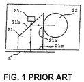
- the apparatus described in this publication utilizes a single square rod shaped glass block 21 shown in FIG. 1 as its optical system and its incident face 21a and reflection/emission face 21b are provided with a filter function, thereby reducing the size of the apparatus and facilitating positioning of the optical system.
- the incident face 21a is provided with a film having a filter function which shields visible light component of excited light while permitting only ultraviolet ray region to pass through, this film being formed by vapor deposition or the like.
- the reflection/emission face 21b is provided with a film having a filter function which reflects the excited light while allowing fluorescence generated from a fluorescent material of a detection object "a" to pass through, this film being formed by the vapor deposition or the like.
- the excited light from the light source 22 is projected onto the detection object "a” like a bill through the detection face 21c by using for example, a UV lamp as the light source 22 and its reflectted light is received by a detector 23 through a reflection/emission face 21b so as to detect a fluorescent material.
- Japanese Patent Application Laid-open No. 8-185558 A has disclosed an apparatus having a detecting function for both fluorescence and reflected ultraviolet ray.
- ultraviolet ray from the UV lamp 32 is irradiated on the detection object "a" through the window 31 having ultraviolet ray transmissibility and its reflected light is received so as to detect fluorescence and reflected ultraviolet ray with the detector 33.
- the detector 33 mounted on a printed circuit board 34 is comprised of a sensor for detecting ultraviolet ray and a sensor for detecting fluorescence each composed of a photo diode and the like, a filter for ultraviolet transmission, a visible light transmitting filter, a micro controller and the like.
- a document such as marketable securities and so on is certified based on both the characteristic relating to reflected ultraviolet ray and characteristic about generation of fluorescence.
- a cold cathode is utilized as a light emission body of the UV lamp, a small sensor suitable for a spot is difficult to make. If the cold cathode is used, a predetermined amount of light is not obtained just when power is turned on, but brightness increases as the temperature increases. Therefore, it is necessary to carry out correction with a passage of time. Further, if it is always turned on, it needs to be replaced at a short time(about a thousand hours) interval because its service life is short. Further, because an inverter is required to drive the cold cathode and the inverter acts as a noise source, it is difficult to detect a weak fluorescent pattern.
- an object of the present invention is to provide a UV/fluorescence detecting apparatus which is capable of detecting both a fluorescent pattern and ultraviolet reflected light, and small and cheap, and a sensing method thereof. Further, another object of the present invention is to provide a UV/fluorescence detecting apparatus capable of detecting a fluorescence of a specific color and a sensing method thereof.
- the present invention relates to a UV/fluorescence detecting apparatus and a sensing method capable of examining the quality of a paper or the like by projecting ultraviolet ray on the paper and detecting an excited fluorescence and a reflected ultraviolet ray.
- a sensor unit comprising: a light source portion including an ultraviolet ray LED for emitting ultraviolet ray through an opening window portion and an ultraviolet ray monitor provided beside the ultraviolet ray LED; a light detector receiving portion disposed in a chamber partitioned with a partition plate for receiving an incident light impinging through the opening window portion; the partition plate for partitioning between the light source portion and the light detector receiving portion; a transparent body provided on the both opening window portions; a first filter provided in a window portion on projection side of the ultraviolet ray for allowing a ultraviolet ray region to pass through; and a second filter provided in a window portion on light receiving side of the incident light for allowing a visible light region to pass through.
- the ultraviolet ray monitor is disposed at a position where it receives both a direct light of the ultraviolet ray and a ultraviolet ray reflected by an object for detecting a light emission amount of the ultraviolet ray and a ultraviolet ray reflected by the object.
- the detected light receiving portion detects a light of wavelength determined to pass through by said second filter.
- a blue filter is attached to the window portion on the light projection side as the first filter while a red filter is attached to the window portion on the light receiving side as the second filter.
- the second filter is provided so as to be replaceable with a filter of the color corresponding to light of color which should be detected.
- the above object is achieved by a sensing method of the UV/fluorescence detecting apparatus comprising a light source portion including an ultraviolet ray LED for emitting ultraviolet ray through a window portion and an ultraviolet ray monitor provided beside the ultraviolet ray LED at a position for receiving both a direct light of the ultraviolet ray and an ultraviolet ray reflected by the surface of a paper sheet and a light receiving sensor for receiving incident light impinging through a window portion of a chamber partitioned with a partition plate from the light source portion, the sensing method comprising: a step for setting the emitted amount of an initial UV light using the ultraviolet ray monitor; a step for reading and memorizing a set value at a waiting time read by the ultraviolet ray monitor; a step for moving a unit having the sensing portion relative to the surface of a paper sheet; a step for sampling visible light with the light receiving sensor; a step for sampling ultraviolet ray with a sensor in the ultraviolet ray monitor; and a
- the UV/fluorescence detecting apparatus In the UV/fluorescence detecting apparatus according to the present invention, its light source is reduced in size by employing an LED(hereinafter referred to as "ultraviolet ray LED") for emitting ultraviolet ray and the sensor unit is made compact by devising the allocation of its peripheral components. Further, by using a structure in which detection of reflected light of ultraviolet ray from a detection object and monitoring of the amount of light from the light source are carried out with a single light receiving device, the quantity of the peripheral circuits is reduced so as to achieve reduction of the size of the apparatus and production cost thereof. Then, a fluorescence receiving portion detects a fluorescence of a wavelength allowed to pass through by a filter.
- FIG. 3 shows a first example of the structure of a sensor portion of the UV/fluorescence detecting apparatus according to the present invention.
- an internal space of the unit case 6 is partitioned to a light source chamber and a fluorescence detecting chamber by a partition plate 6a for shielding light including visible light and ultraviolet ray.
- An opening window portion 6b is provided on the side of a path on which a paper sheet is carried and ultraviolet ray is projected through the opening window portion 6b in the light source chamber so as to receive light from the paper sheet.
- an above portion of the opening window portion 6b of the respective chambers divided with the partition plate 6a is covered with a transparent body 6c such as glass which allows ultraviolet ray and visible light to pass through.
- a slope is provided at an entering side of a paper sheet in the transparent body 6c.
- the sensor unit 10a is mounted on the transportation path through a mounting member 6d so that a top face of the transparent body 6c is a part of the path.
- an optical filter 3 for allowing ultraviolet ray range to pass through is attached and in window portion of the fluorescence detecting chamber, an optical filter 4 for allowing visible light range to pass through is attached.
- a blue color component filter (hereinafter referred to as "blue filter”) is applied as the optical filter 3 and a filter having a color matching with the color of fluorescence which should be detected(red, orange, yellow and so on) is applied as the optical filter 4.
- each filter is provided at each window portion so that it can be replaced.
- red fluorescence is a detection object and a filter which allows fluorescence of red color component(about 600 nm to about 770 nm in wavelength) to pass through(hereinafter referred to as "red filter”) is attached to the window portion on the fluorescence detecting side.
- a light source portion 1 comprising an ultraviolet ray LED 1a for emitting ultraviolet ray and an ultraviolet ray monitor(monitor sensor for receiving ultraviolet ray) 1b are provided in the light source chamber.
- an ultraviolet monitor 1b is disposed beside it at such a position in which it is capable of receiving both a direct light from the ultraviolet ray LED 1a and ultraviolet reflected and diffused ultraviolet light from the paper sheet as shown with arrows in FIG. 3 and output saturation never occurs.
- detection of the light amount of the light source and detection of the ultraviolet reflected light are carried out with a single light receiving device.
- a detection light detector 2 for receiving a light impinging through the opening window portion 6b is provided in the chamber on the fluorescence detection side.
- the detection light receiving portion 2 includes a fluorescence receiving sensor 2a(hereinafter referred to as "detecting sensor") for detecting light of wavelength including at least visible light region and detects light of the wavelength which is determined to allow to pass through by the filter 4.
- detecting sensor a fluorescence receiving sensor 2a(hereinafter referred to as "detecting sensor") for detecting light of wavelength including at least visible light region and detects light of the wavelength which is determined to allow to pass through by the filter 4.
- a rod lens 2b is provided and by converging light from the paper sheet through this rod lens 2b, a weak fluorescence can be detected. Meanwhile, although the rod lens 2b is attached for such a weak fluorescence, this may not be attached if a strong fluorescence can be obtained.
- the aforementioned ultraviolet ray LED 1a, the ultraviolet monitor 1b and the fluorescence detecting sensor 2a are mounted on a common substrate 5 and signals from the respective light receiving sensors 1b, 2a are outputted through an I-V(current-voltage) converting circuit(not shown).
- an I-V(current-voltage) converting circuit not shown.
- a photo diode having a rectangular light receiving face is employed and two ultraviolet ray LEDs 1a are provided in parallel. Data of a rectangular region perpendicular to the transportation direction A of the paper sheet is sampled.
- an ultraviolet ray LED having an emission spectrum(emission wavelength is about 370 nm) as shown in FIG. 4A is employed as a light source which emits ultraviolet ray and the directional characteristic thereof is as shown in FIG. 4B.
- a filter(blue filter 4) which allows ultraviolet ray from this ultraviolet ray LED to pass through it is desirable to use a band pass filter having a maximum transmissibility at 370 nm corresponding to the characteristic of ultraviolet ray LED.
- a filter of a color corresponding to the color of fluorescence which should be detected is employed, in case of the red filter 4 of this embodiment, it is desirable to employ a band pass filter which allows visible light to pass through and has the maximum transmissibility near about 620 nm wavelength or a visible light transmission filter which allows light of about 620 nm to pass through.
- the fluorescence detecting sensor 2a for detecting fluorescence has a different spectral response character from the monitor sensor 1b for detecting ultraviolet ray
- the ultraviolet monitor 1b it is desirable to use an ultraviolet reinforcing photo diode indicating a high sensitivity to light having emission wavelength(about 370 nm in this example) of the ultraviolet LED.
- the fluorescence and ultraviolet ray of an appropriate wavelength from the object are received through each filter, it is permissible to use the same photo diode.
- a photo diode PD1(or PD2a, PD2b) having a sensitivity characteristic of about 320-1100 nm(maximum sensitivity wavelength about 960 nm) including emission wavelength region of ultraviolet ray LED as shown in FIG. 5A. Further, it is desirable to use a photo diode(the same figure indicates examples of PD2a, PD2b) having a directional characteristic shown in FIG. 5B. Meanwhile if the photo diode PD1 shown in FIG. 5A is employed, the light receiving sensitivity is 0.15 A/W for ultraviolet ray of 370 nm and 0.38 A/W for red light and infrared light.
- the ultraviolet ray monitor 1b As for the allocation of the ultraviolet ray monitor 1b, although, in the example shown in FIG. 3, the ultraviolet ray monitor 1b is provided at a place which is weak in emitted amount of the ultraviolet ray LED 1a, this can obtain a sufficient output as a monitor for emitted light amount because it is very near the ultraviolet ray emitting portion. Contrary to this, because the reflected light from the paper sheet is dispatched from a far distance, this monitor needs to be disposed in a direction excellent in its sensitivity. As a result, as the example FIG.
- the monitor is preferred to be located at a position enabling both the reflected light from the paper sheet and a direct light from the light source to be received and allowing a compact structure ensuring an excellent sensitivity, the position being in the vicinity of the ultraviolet ray LED 1a and not causing the output of the photo diode to be saturated.
- the ultraviolet ray projected from the ultraviolet ray LED 1a impinges directly upon the ultraviolet ray monitor 1b so that the light amount is detected. Meanwhile, this detection of the light amount is carried out with no medium existing on the window portion or while a direct light from the ultraviolet ray LED 1a is entered into the ultraviolet ray monitor 1b but no reflected light from the paper sheet is entered.
- the ultraviolet ray passing through the blue filter 3 is reflected on the paper sheet at the focal point of the ultraviolet ray LED 1a while as for light impinging from the window portion on the ultraviolet ray projection side, its ultraviolet ray region passes through the blue filter 3 and then, the ultraviolet reflected diffused light from the paper sheet impinges upon the ultraviolet ray monitor 1b and is detected.
- FIG. 6 shows a second example of the structure of the sensing portion, in which light through the red filter 4 from the paper sheet is received directly by the detecting sensor 2a.
- the detecting sensor 1b is disposed such that it adjoins the face of the opening window portion 6b(face of the red filter 4) as shown in FIG. 6 depending on the directional characteristic thereof.
- other structure of the sensing portion is the same as the first example and therefore, a description thereof is omitted as the same reference numerals are attached.
- the detection accuracy is raised by adjusting the focal point on a medium face and sensor surface by means of the rod lens 2b as shown in the first example(see FIG. 3), the adjustment of the focal point is not necessary if a method of using a block value in a processing after the sampling is carried out.
- FIG. 7 shows a third example of the structure of the sensing portion, in which a light receiving face of the ultraviolet ray monitor 1b is disposed obliquely above the light emission portion of the ultraviolet ray LED 1a.
- the ultraviolet ray monitor 1b is disposed not on the side of the partition plate 6a with respect to the optical axis of the ultraviolet ray LED 1a but on an opposite side to the partition plate 6a.
- the ultraviolet ray monitor 1b is disposed at a position which allows both the direct light from the ultraviolet ray LED 1a and the reflected light from the paper sheet to be received and causes no saturation of the output.
- part of the ultraviolet monitor 1b is inserted into an opening portion formed in the blue filter 4 and attached to a substrate on the side wall( or substrate 5 on the bottom with a relatively long lead wire).
- the ultraviolet ray monitor 1b can be provided at a place in which the light emission of the ultraviolet ray LED 1a is strong.
- FIGs. 8A-8D show an appearance of the sensing unit exemplified in the first-third examples.
- FIG. 8A is a plan view of the sensing unit 10a seen from the bottom
- FIG. 8B is a side view of the FIG. 8A seen from the direction of an arrow X
- FIG. 8C is a side view of the FIG. 8A seen from the direction of an arrow Y
- FIG. 8D is a plan view seen from a top face(window portion side).
- the sensor unit 10a is connected to an external unit through an outside connecting connector 7.
- L2 20 mm
- L3 26.7 mm.
- the transparent body 6c provided on the opening window portion 6b is 16 x 9 mm while its reading effective range is 10 x 1.5 mm.
- the sensor unit mounting space is about 27.5 x 20 x 26.7 mm, which is quite compacter than a conventional sensor unit(a mounting space of a conventional example reduced in size is, for example, about 55 x 34 x 17.2 mm) using a cold cathode as its light emitting body.
- the size of the opening window portion 6b, size of the reading effective range and the like are not restricted to the above described examples.
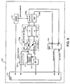
- FIG. 9 shows an example of the circuit structure of the UV/fluorescence detecting apparatus and in this example, an area indicated by reference numeral 10a is a circuit accommodated in the sensor unit.
- an LED control circuit 12 for ON/OFF control on the ultraviolet ray LED 1a, a D/A converter 13, a gain adjusting circuit 14 for carrying out gain adjustment in the detecting sensor 2a and a multiplexer(MPX) 16 for switching the outputs of the ultraviolet ray monitor 1b and the detecting sensor 2a are connected to the output port of a CPU 11 mounted on the UV/fluorescence detecting apparatus 10.
- a constant current circuit 17 is connected to the output of the D/A converter 13 so as to adjust the light emission amount of the ultraviolet ray LED 1a through this constant current circuit 17.
- Step S1 Upon adjustment of the sensor unit, current is supplied at a predetermined initial current value(10 mA in this example) without any medium(detection object) so as to emit the ultraviolet ray LED 1a(Step S1).
- Output data(MON data) of the ultraviolet monitor 1b is collected(Step S2).
- Step S3 whether or not the output value of the ultraviolet ray monitor 1b is within a reference value range(reference voltage Va ⁇ ⁇ : 2.3 ⁇ 0.05V in this example) is determined(Step S3) and if it is out of the range, the light emission amount of the ultraviolet ray LED 1a is adjusted through the constant current circuit 17 so as to be within the reference value range(Step S4).
- Step S7 Whether or not the output value is within the reference value range(reference voltage Vb ⁇ ⁇ : 3.0 ⁇ 0.05V in this example) is determined(Step S7) and if it is out of the reference value range, gain adjustment is carried out through the gain adjusting circuit 14 so that the output value of the ultraviolet ray LED 1a is within the reference value range(Step S8). If it is within the reference value range, an adjusted result is stored(Step S9) and the adjustment processing prior to shipment is terminated.
- the reference current is supplied at a predetermined interval so as to turn ON/OFF the ultraviolet ray LED 1a(Step S11) and then, ON/OFF is confirmed.
- Step S12 whether or not the output of the ultraviolet ray monitor 1b is within the range of ON/OFF confirmation reference value is determined(Step S12). If it is out of the range, it is determined that the sensor is abnormal and then, processing against abnormality such as alarm sounding is carried out and the adjustment operation is terminated(Step S13). If it is within the range in the aforementioned Step S12, an initial value is read(Step S14).
- the ultraviolet ray LED 1a is turned ON without any medium so as to obtain output data(MON data) of the ultraviolet ray monitor 1b(Step S15) and whether or not the output value is within the reference value range(reference voltage Va ⁇ ⁇ : 2.3 ⁇ 0.05V in this example) is determined(Step S16). If it is out of the range, the light emission amount of the ultraviolet ray LED 1a is adjusted to be within the reference value range through the constant current circuit 17(Step S17).
- MON data(data of direct light) after the above-described adjustment is set up as a correction value at the time of sampling the reflected ultraviolet ray and an adjusted result is stored(Step S18) and then the adjustment processing at the waiting time is terminated.
- the UV/fluorescence detecting apparatus starts the sampling operation by detecting a coming of the paper sheet into the window portion of the sensor unit(Step S21).
- a mechanical clock which is a pulse synchronous with transportation over a predetermined distance
- a control pulse is generated, so that detecting data at each predetermined transported distance of the paper sheet(relative moving distance) is sampled. That is, whether or not the mechanical clock is "1" as the result of detection of paper sheet invasion is determined(Step S22). If it is "1", the sensor output is changed over by the multiplexer(MPX) 15, and data of the detecting sensor 2a and data of the ultraviolet ray monitor 1b are sampled. In this sample, as indicated with the sensor structure of FIG.
- Step S25 whether or not collection of data of the predetermined sampling number is completed is determined(Step S25). If it is not completed, the processing proceeds to the aforementioned Step S22, in which the sampling processing of each transportation of predetermined distance is repeated. If it is determined that the collection of data is completed in the Step S25, the data sampling processing for the paper sheet is terminated.
- Step S31 the reference data on the wavelength(fluorescence of a color corresponding to a filter color) of a true bill of the denomination is verified with the sampled fluorescence data. For example, by discriminating a fluorescent pattern and the like by comparing each fluorescence sample value with an appropriate reference value, the authenticity of the bill is judged(Step S32). If it is determined that the bill is true, with an adjustment value(data about direct light in the condition in which there is no medium) set up at the waiting time as an offset value and the previously described gain adjustment result value as a gain value, ultraviolet reflected data is obtained according to the following expression (1) (Step S33).
- Ultraviolet reflection data (ultraviolet ray data - offset) x gain
- Step S35 false bill determining process(Step S35) for that paper sheet is carried out according to preliminarily registered false bill data using fluorescence data and ultraviolet reflection data. If it is determined that the bill is true in the Step S34, true bill determining process(Step S36) is carried out using detection information of other sensors(image sensor, magnetic sensor or the like) and then, the true bill authentication processing for that bill is terminated.
- the paper sheet using the characteristic upon ultraviolet ray irradiation in order to prevent forgery and doctoring includes a case where a special paper is used to prevent fluorescence from being emitted even if it is irradiated(US dollars and the like), a case where ultraviolet ray is reflected at only a predetermined position, a case where a specific pattern is printed using fluorescent ink and the like.
- a type which when irradiated with ultraviolet ray, reflects ultraviolet ray of a low level while emitting fluorescence a type which reflects ultraviolet ray of a low level while having the characteristic of not emitting fluorescence(forged bill made by color copy)
- a type which reflects ultraviolet ray of a high level while having the characteristic of emitting fluorescence a type which reflects ultraviolet ray of a high level while having the characteristic of not emitting fluorescence(forged bill made of a high quality paper) and the like.
- the paper sheet on which valuable information is printed has been picked up as an example for the description
- the present invention is not restricted to securities such as bill and check, however, it can be applied to a certifying apparatus for a document of other type requiring certification(including paper attached with seal or the like and paper written by stamp, sign or the like) and also a system in which detecting information is transmitted from a UV/fluorescence detecting apparatus to a host computer through communication network and processed.
- the present invention achieves a small and compact sensor structure by using an LED as an ultraviolet ray emitting body and reducing the quantity of peripheral circuits, a small, cheap UV/fluorescence detecting apparatus can be provided.
- a small, cheap UV/fluorescence detecting apparatus can be provided.
- the ultraviolet ray monitor is disposed beside the UV emitting device(ultraviolet ray LED) so as to be capable of receiving a direct light from the UV emitting device and a ultraviolet ray reflected by a detection object, monitoring of the light amount of a light source and detection of ultraviolet reflected light can be carried out with a single light receiving device.
- reflected light intensity of ultraviolet ray reflected by the paper sheet can be detected by an ultraviolet ray monitor so as to achieve reduction in the size and price of the sensor unit.
- the light source portion including the ultraviolet ray monitor and the detection light receiving portion are partitioned with the partition wall and visible light region thereof is received through the window portion in a chamber on the detection light receiving side, the visible light can be also detected independently.
- the LED is employed as the UV emitting device, an inverter power supply using the cold cathode is not required, and therefore, no unnecessary noise is generated from the light source and no heat is generated.
- the service life is shorter than a conventional type using the cold cathode.
- the cold cathode is not capable of securing a predetermined amount of light emission unless the temperature of that tube increases to a predetermined temperature, the ultraviolet ray LED attains sufficient brightness early after it is powered on.
- the control is simplified and its driving circuit is also simplified, thereby achieving a low cost of the UV/fluorescence detecting apparatus.
Landscapes
- Health & Medical Sciences (AREA)
- General Health & Medical Sciences (AREA)
- Toxicology (AREA)
- Physics & Mathematics (AREA)
- General Physics & Mathematics (AREA)
- Inspection Of Paper Currency And Valuable Securities (AREA)
- Investigating, Analyzing Materials By Fluorescence Or Luminescence (AREA)
- Photometry And Measurement Of Optical Pulse Characteristics (AREA)
- Investigating Materials By The Use Of Optical Means Adapted For Particular Applications (AREA)
Applications Claiming Priority (2)
| Application Number | Priority Date | Filing Date | Title |
|---|---|---|---|
| JP2000394560 | 2000-12-26 | ||
| JP2000394560A JP2002197506A (ja) | 2000-12-26 | 2000-12-26 | Uv・蛍光検出装置及びそのセンシング方法 |
Publications (2)
| Publication Number | Publication Date |
|---|---|
| EP1220165A2 true EP1220165A2 (fr) | 2002-07-03 |
| EP1220165A3 EP1220165A3 (fr) | 2004-03-10 |
Family
ID=18860172
Family Applications (1)
| Application Number | Title | Priority Date | Filing Date |
|---|---|---|---|
| EP01129446A Withdrawn EP1220165A3 (fr) | 2000-12-26 | 2001-12-10 | Appareil pour détecter la fluorescence ultra-violet et méthode de détection correspondante |
Country Status (4)
| Country | Link |
|---|---|
| US (1) | US6603126B2 (fr) |
| EP (1) | EP1220165A3 (fr) |
| JP (1) | JP2002197506A (fr) |
| CN (1) | CN1220046C (fr) |
Cited By (14)
| Publication number | Priority date | Publication date | Assignee | Title |
|---|---|---|---|---|
| WO2004048947A1 (fr) * | 2002-11-21 | 2004-06-10 | Cdex, Inc. | Procedes et appareil pour la detection, le controle et la classification d'especes moleculaires par fluorescence d'ultraviolet |
| US7094364B2 (en) | 2003-11-26 | 2006-08-22 | General Electric Company | Method of authenticating polymers, authenticatable polymers, methods of making authenticatable polymers and authenticatable articles, and articles made there from |
| US7154102B2 (en) | 2002-11-21 | 2006-12-26 | Cdex, Inc. | System and methods for detection and identification of chemical substances |
| US7169615B2 (en) | 2003-11-26 | 2007-01-30 | General Electric Company | Method of authenticating polymers, authenticatable polymers, methods of making authenticatable polymers and authenticatable articles, and articles made there from |
| US7175086B2 (en) | 2004-04-21 | 2007-02-13 | General Electric Company | Authentication system, data device, and methods for using the same |
| US7312257B2 (en) | 2003-01-23 | 2007-12-25 | General Electric Company | Polymer encapsulation of high aspect ratio materials and methods of making same |
| US7355944B2 (en) | 2004-11-12 | 2008-04-08 | General Electric Company | Authenticatable media and method of authenticating |
| US7381972B1 (en) | 2006-07-24 | 2008-06-03 | Science Applications International Corporation | System and method for light fluorescence detection |
| US7496938B2 (en) | 2003-11-24 | 2009-02-24 | Sabic Innovative Plastics Ip B.V. | Media drive with a luminescence detector and methods of detecting an authentic article |
| US7597961B2 (en) | 2004-07-13 | 2009-10-06 | Sabic Innovative Plastics Ip B.V. | Authenticatable article and method of authenticating |
| WO2010081507A1 (fr) * | 2009-01-15 | 2010-07-22 | Beb Industrie -Elektronik Ag | Dispositif et procédé de détection de lumière réfléchie et/ou émise par un objet |
| EP2453418A1 (fr) * | 2010-11-12 | 2012-05-16 | Beb Industrie-Elektronik AG | Procédé et dispositif de contrôle de l'authenticité de chèques dotés de fenêtres de sécurité |
| US8610441B2 (en) | 2009-01-12 | 2013-12-17 | Beb Industrie-Elektronik Ag | Device for determining a thickness or thickness variation of a flat object |
| US10180248B2 (en) | 2015-09-02 | 2019-01-15 | ProPhotonix Limited | LED lamp with sensing capabilities |
Families Citing this family (54)
| Publication number | Priority date | Publication date | Assignee | Title |
|---|---|---|---|---|
| EP1167964B1 (fr) * | 1999-03-31 | 2010-05-05 | Hitachi-GE Nuclear Energy, Ltd. | Procede et appareil d'essai non destructif |
| US7119345B2 (en) * | 2003-02-28 | 2006-10-10 | Applera Corporation | Excitation and emission filter |
| GB0002977D0 (en) * | 2000-02-09 | 2000-03-29 | Rue De Int Ltd | Detector |
| US6491408B1 (en) * | 2001-07-05 | 2002-12-10 | Spectronics Corporation | Pen-size LED inspection lamp for detection of fluorescent material |
| US8436268B1 (en) * | 2002-08-12 | 2013-05-07 | Ecullet | Method of and apparatus for type and color sorting of cullet |
| EP1445099A1 (fr) * | 2003-02-10 | 2004-08-11 | Kba-Giori S.A. | Capteur |
| US20040256581A1 (en) * | 2003-06-20 | 2004-12-23 | David Au | Hand-held ultraviolet sterilization lamp |
| CN1898704B (zh) * | 2004-02-12 | 2010-04-21 | 日本电产科宝株式会社 | 检查装置 |
| DE102004024494B4 (de) * | 2004-05-16 | 2019-10-17 | Dürr Dental SE | Medizinische Kamera |
| WO2006022823A1 (fr) * | 2004-07-29 | 2006-03-02 | Centrus International, Inc. | Détection de micro-organismes à l’aide d’un dispositif à fluorescence |
| US20060202132A1 (en) * | 2005-03-14 | 2006-09-14 | Chua Janet B Y | Portable fluorescence detection unit adapted for eye protection |
| JP4901228B2 (ja) * | 2006-02-07 | 2012-03-21 | 株式会社東芝 | 分光検出装置 |
| US20080049414A1 (en) * | 2006-02-10 | 2008-02-28 | Mckay William D Sr | Stain and odor detection and cleanup system |
| US20070189834A1 (en) * | 2006-02-10 | 2007-08-16 | Thethe Hartz Mountain Corporation | Stain and odor detection and cleanup system |
| JP2006284596A (ja) * | 2006-05-08 | 2006-10-19 | Fujitsu Ltd | 撮影装置 |
| JP2006220666A (ja) * | 2006-05-08 | 2006-08-24 | Fujitsu Ltd | 撮影装置 |
| US20080049972A1 (en) * | 2006-07-07 | 2008-02-28 | Lockheed Martin Corporation | Mail imaging system with secondary illumination/imaging window |
| US20080035866A1 (en) * | 2006-07-07 | 2008-02-14 | Lockheed Martin Corporation | Mail imaging system with UV illumination interrupt |
| US20080019563A1 (en) * | 2006-07-07 | 2008-01-24 | Goodwin Mark D | Mail processing system with low resolution UV imaging subsystem |
| US20080012981A1 (en) * | 2006-07-07 | 2008-01-17 | Goodwin Mark D | Mail processing system with dual camera assembly |
| US20080011654A1 (en) * | 2006-07-07 | 2008-01-17 | Hale Mathew S | Mail processing system with radiation filtering |
| JP2009145149A (ja) | 2007-12-13 | 2009-07-02 | Shimadzu Corp | 分光光度計 |
| CA3162577C (fr) | 2008-05-20 | 2023-09-26 | University Health Network | Dispositif et procede pour imagerie et surveillance par fluorescence |
| WO2009147232A1 (fr) * | 2008-06-05 | 2009-12-10 | Bohle Ag | Dispositif de détermination par fluorescence de la présence d'éléments sur une surface |
| US9308289B2 (en) * | 2009-02-05 | 2016-04-12 | Koninklijke Philips N.V. | Air purifying luminaire |
| US20100230330A1 (en) * | 2009-03-16 | 2010-09-16 | Ecullet | Method of and apparatus for the pre-processing of single stream recyclable material for sorting |
| CN101893809B (zh) * | 2010-06-30 | 2012-07-25 | 亚亚科技股份有限公司 | 荧光摄影的光源装置 |
| CN103620779B (zh) | 2011-07-19 | 2016-12-28 | 赫普塔冈微光有限公司 | 光电模块及其制造方法 |
| JP2013083528A (ja) * | 2011-10-07 | 2013-05-09 | Vienex Corp | 密着型光学ラインセンサ装置及び有価紙面の鑑別方法 |
| DE102011116487A1 (de) * | 2011-10-20 | 2013-04-25 | Giesecke & Devrient Gmbh | Verschmutzungsprüfung des Fensters einer Messvorrichtung |
| CN102495036A (zh) * | 2011-12-07 | 2012-06-13 | 长春美泰科技有限公司 | 生活用纸制品荧光增白剂现场检测仪 |
| EP2682739B1 (fr) * | 2012-07-05 | 2024-09-04 | Atlas Material Testing Technology GmbH | Test climatique à diverses longueurs d'onde uv de diodes électroluminiscentes uv |
| JP5971800B2 (ja) * | 2012-09-19 | 2016-08-17 | 株式会社小森コーポレーション | シート状物の検査装置 |
| CN103077563B (zh) * | 2012-11-21 | 2015-09-09 | 北京兆维电子(集团)有限责任公司 | 基于红外、紫外和磁性检测的票据鉴伪装置 |
| EP3006910A4 (fr) * | 2013-05-29 | 2017-02-08 | Konica Minolta, Inc. | Dispositif d'éclairage et dispositif de mesure de caractéristiques de réflexion |
| KR101465694B1 (ko) * | 2013-08-19 | 2014-12-01 | 한국표준과학연구원 | 자외선 지수 측정 장치 |
| CN103808658B (zh) * | 2014-02-17 | 2015-12-30 | 中国人民银行印制科学技术研究所 | 一种片状材料透视检测装置 |
| KR101620692B1 (ko) * | 2014-06-27 | 2016-05-12 | 주식회사 엘지씨엔에스 | 물체 감지 장치 및 방법과 그를 이용한 금융 기기 |
| WO2016011534A1 (fr) | 2014-07-24 | 2016-01-28 | University Health Network | Collecte et analyse de données à des fins de diagnostic |
| WO2016158840A1 (fr) * | 2015-04-01 | 2016-10-06 | キヤノン・コンポーネンツ株式会社 | Unité capteur d'image, dispositif de lecture d'image, dispositif de formation d'image et dispositif d'identification de feuille de papier |
| DE102016000012A1 (de) * | 2016-01-05 | 2017-07-06 | Giesecke & Devrient Gmbh | Echtheitsprüfung von Wertdokumenten |
| US20170320083A1 (en) * | 2016-05-04 | 2017-11-09 | CG&Hayward, LLC | Sprayer nozzle with embedded battery-operated ultraviolet light(s) |
| CN207074170U (zh) * | 2016-06-02 | 2018-03-06 | 汉高(中国)投资有限公司 | 便携式紫外光激发荧光检测仪 |
| JP6944259B2 (ja) * | 2017-03-27 | 2021-10-06 | グローリー株式会社 | 燐光検出装置、紙葉類処理装置及び燐光検出方法 |
| JP6944258B2 (ja) * | 2017-03-27 | 2021-10-06 | グローリー株式会社 | 燐光検出装置、紙葉類処理装置及び燐光検出方法 |
| WO2018181134A1 (fr) * | 2017-03-27 | 2018-10-04 | グローリー株式会社 | Capteur optique, dispositif de détection de lumière, dispositif de traitement de feuille de papier, procédé de détection de lumière et dispositif de détection de phosphorescence |
| JP7017862B2 (ja) * | 2017-03-27 | 2022-02-09 | グローリー株式会社 | 光センサ、光検出装置、紙葉類処理装置及び光検出方法 |
| GB2570706B (en) * | 2018-02-05 | 2020-10-14 | Innovative Tech Ltd | A banknote validator |
| CN111771100B (zh) | 2018-02-28 | 2023-08-11 | 贝卡尔特先进帘线阿尔特公司 | 用于检测丝上的涂层的设备以及使用该设备的方法 |
| JP2021004809A (ja) * | 2019-06-26 | 2021-01-14 | マークテック株式会社 | 紫外線led照射装置 |
| US11389339B2 (en) | 2019-08-16 | 2022-07-19 | Verily Life Sciences Llc | Determining a presence of auto-fluorescent biological substances through an article |
| US12297041B1 (en) | 2019-09-20 | 2025-05-13 | Verily Life Sciences Llc | Smart diaper pail |
| TWI726583B (zh) * | 2020-01-16 | 2021-05-01 | 國立臺灣科技大學 | 警示模組 |
| CN115015206B (zh) * | 2022-07-15 | 2022-11-11 | 合肥工业大学 | 基于紫外荧光法的玻璃表面洁净度检测装置及检测方法 |
Citations (1)
| Publication number | Priority date | Publication date | Assignee | Title |
|---|---|---|---|---|
| JPH06309546A (ja) | 1993-04-27 | 1994-11-04 | Furukawa Electric Co Ltd:The | 蛍光検出装置 |
Family Cites Families (9)
| Publication number | Priority date | Publication date | Assignee | Title |
|---|---|---|---|---|
| US3956630A (en) * | 1975-03-14 | 1976-05-11 | Westvaco Corporation | Fluorimetric coat weight measurement |
| JPH0390845A (ja) * | 1989-09-01 | 1991-04-16 | Hitachi Ltd | 表面分析方法およびその装置 |
| US5640463A (en) * | 1994-10-04 | 1997-06-17 | Cummins-Allison Corp. | Method and apparatus for authenticating documents including currency |
| WO1995019019A2 (fr) * | 1994-01-04 | 1995-07-13 | Mars, Incorporated | Detection de faux, notamment de faux billets de banque |
| ZA967500B (en) * | 1995-12-21 | 1998-03-05 | Unilever Plc | Device for the identification of acne, microcomedones, and bacteria on human skin. |
| US5942759A (en) * | 1996-12-24 | 1999-08-24 | Romano; Camille | Counterfeit detection viewer apparatus having a removable counterfeit detector unit for paper currency |
| DE69837839T2 (de) * | 1997-03-07 | 2007-12-13 | Clare Chemical Research LLC, Denver | Fluorometrischer Nachweis mit sichtbarem Light |
| ES2268822T3 (es) * | 1998-10-23 | 2007-03-16 | Bundesdruckerei Gmbh | Elemento semiconductor solido electroluminiscente como medio de comprobacion para caracteristicas de seguridad luminiscente. |
| US6369882B1 (en) * | 1999-04-29 | 2002-04-09 | Advanced Sorting Technologies Llc | System and method for sensing white paper |
-
2000
- 2000-12-26 JP JP2000394560A patent/JP2002197506A/ja active Pending
-
2001
- 2001-12-10 EP EP01129446A patent/EP1220165A3/fr not_active Withdrawn
- 2001-12-11 US US10/020,454 patent/US6603126B2/en not_active Expired - Lifetime
- 2001-12-26 CN CNB011447532A patent/CN1220046C/zh not_active Expired - Fee Related
Patent Citations (1)
| Publication number | Priority date | Publication date | Assignee | Title |
|---|---|---|---|---|
| JPH06309546A (ja) | 1993-04-27 | 1994-11-04 | Furukawa Electric Co Ltd:The | 蛍光検出装置 |
Cited By (17)
| Publication number | Priority date | Publication date | Assignee | Title |
|---|---|---|---|---|
| US7154102B2 (en) | 2002-11-21 | 2006-12-26 | Cdex, Inc. | System and methods for detection and identification of chemical substances |
| WO2004048947A1 (fr) * | 2002-11-21 | 2004-06-10 | Cdex, Inc. | Procedes et appareil pour la detection, le controle et la classification d'especes moleculaires par fluorescence d'ultraviolet |
| US7312257B2 (en) | 2003-01-23 | 2007-12-25 | General Electric Company | Polymer encapsulation of high aspect ratio materials and methods of making same |
| US7496938B2 (en) | 2003-11-24 | 2009-02-24 | Sabic Innovative Plastics Ip B.V. | Media drive with a luminescence detector and methods of detecting an authentic article |
| US7094364B2 (en) | 2003-11-26 | 2006-08-22 | General Electric Company | Method of authenticating polymers, authenticatable polymers, methods of making authenticatable polymers and authenticatable articles, and articles made there from |
| US7169615B2 (en) | 2003-11-26 | 2007-01-30 | General Electric Company | Method of authenticating polymers, authenticatable polymers, methods of making authenticatable polymers and authenticatable articles, and articles made there from |
| US7175086B2 (en) | 2004-04-21 | 2007-02-13 | General Electric Company | Authentication system, data device, and methods for using the same |
| US7597961B2 (en) | 2004-07-13 | 2009-10-06 | Sabic Innovative Plastics Ip B.V. | Authenticatable article and method of authenticating |
| US7355944B2 (en) | 2004-11-12 | 2008-04-08 | General Electric Company | Authenticatable media and method of authenticating |
| US7468520B1 (en) | 2006-07-24 | 2008-12-23 | Science Applications International Corporation | System and method for light induced fluorescence detection |
| US7381972B1 (en) | 2006-07-24 | 2008-06-03 | Science Applications International Corporation | System and method for light fluorescence detection |
| US8610441B2 (en) | 2009-01-12 | 2013-12-17 | Beb Industrie-Elektronik Ag | Device for determining a thickness or thickness variation of a flat object |
| WO2010081507A1 (fr) * | 2009-01-15 | 2010-07-22 | Beb Industrie -Elektronik Ag | Dispositif et procédé de détection de lumière réfléchie et/ou émise par un objet |
| US8472025B2 (en) | 2009-01-15 | 2013-06-25 | Beb Industrie-Elektronik Ag | Device and method for detecting reflected and/or emitted light of an object |
| DE102009005171B4 (de) * | 2009-01-15 | 2025-05-08 | Beb Industrie-Elektronik Ag | Vorrichtung und Verfahren zum Nachweis von reflektiertem und/oder emittiertem Licht eines Gegenstandes |
| EP2453418A1 (fr) * | 2010-11-12 | 2012-05-16 | Beb Industrie-Elektronik AG | Procédé et dispositif de contrôle de l'authenticité de chèques dotés de fenêtres de sécurité |
| US10180248B2 (en) | 2015-09-02 | 2019-01-15 | ProPhotonix Limited | LED lamp with sensing capabilities |
Also Published As
| Publication number | Publication date |
|---|---|
| US6603126B2 (en) | 2003-08-05 |
| US20020079454A1 (en) | 2002-06-27 |
| CN1220046C (zh) | 2005-09-21 |
| CN1362621A (zh) | 2002-08-07 |
| EP1220165A3 (fr) | 2004-03-10 |
| JP2002197506A (ja) | 2002-07-12 |
Similar Documents
| Publication | Publication Date | Title |
|---|---|---|
| US6603126B2 (en) | UV/fluorescence detecting apparatus and sensing method thereof | |
| US8837025B2 (en) | Image reading device | |
| US6768123B2 (en) | Apparatus for examining documents | |
| RU2183861C2 (ru) | Способ установления подлинности документа, аппарат и система для его осуществления | |
| CN102169607B (zh) | 检查有价文件的设备 | |
| JP4609531B2 (ja) | 画像読取装置 | |
| AU2004296413B2 (en) | Reflective optical sensor for bill validator | |
| US7711175B2 (en) | Image reading apparatus | |
| US6881962B2 (en) | Paper fluorescence detection sensor | |
| JP2001052232A (ja) | 紙葉類真偽識別装置 | |
| WO2003073384A1 (fr) | Capteur detectant la fluorescence de feuilles | |
| JP4163822B2 (ja) | 紙葉類用の蛍光検出装置 | |
| HK1047650A (en) | Uv/fluorescence detecting apparatus and sensing method thereof | |
| JP2003162748A (ja) | 紙葉類蛍光検出センサ | |
| JP2004334342A (ja) | 紙葉類蛍光検出装置 | |
| JP2001056877A (ja) | 紙葉類のスレッド検出方法及びその装置 | |
| JP2003115071A (ja) | 偽造鑑別装置及び方法 | |
| JP2003263667A (ja) | 紙葉類蛍光検出センサ | |
| JPH05332951A (ja) | 光センサ | |
| JP2003296792A (ja) | 紙葉類蛍光検出センサ | |
| JPH075103A (ja) | 磁気インキ検出装置 |
Legal Events
| Date | Code | Title | Description |
|---|---|---|---|
| PUAI | Public reference made under article 153(3) epc to a published international application that has entered the european phase |
Free format text: ORIGINAL CODE: 0009012 |
|
| AK | Designated contracting states |
Kind code of ref document: A2 Designated state(s): AT BE CH CY DE DK ES FI FR GB GR IE IT LI LU MC NL PT SE TR |
|
| AX | Request for extension of the european patent |
Free format text: AL;LT;LV;MK;RO;SI |
|
| PUAL | Search report despatched |
Free format text: ORIGINAL CODE: 0009013 |
|
| AK | Designated contracting states |
Kind code of ref document: A3 Designated state(s): AT BE CH CY DE DK ES FI FR GB GR IE IT LI LU MC NL PT SE TR |
|
| AX | Request for extension of the european patent |
Extension state: AL LT LV MK RO SI |
|
| AKX | Designation fees paid | ||
| REG | Reference to a national code |
Ref country code: DE Ref legal event code: 8566 |
|
| STAA | Information on the status of an ep patent application or granted ep patent |
Free format text: STATUS: THE APPLICATION IS DEEMED TO BE WITHDRAWN |
|
| 18D | Application deemed to be withdrawn |
Effective date: 20040911 |
|
| REG | Reference to a national code |
Ref country code: HK Ref legal event code: WD Ref document number: 1047650 Country of ref document: HK |