EP1220347A2 - Polymerelektrolyt-Brennstoffzellenstapel - Google Patents
Polymerelektrolyt-Brennstoffzellenstapel Download PDFInfo
- Publication number
- EP1220347A2 EP1220347A2 EP01310790A EP01310790A EP1220347A2 EP 1220347 A2 EP1220347 A2 EP 1220347A2 EP 01310790 A EP01310790 A EP 01310790A EP 01310790 A EP01310790 A EP 01310790A EP 1220347 A2 EP1220347 A2 EP 1220347A2
- Authority
- EP
- European Patent Office
- Prior art keywords
- inlet
- outlet
- manifold aperture
- separator
- anode
- Prior art date
- Legal status (The legal status is an assumption and is not a legal conclusion. Google has not performed a legal analysis and makes no representation as to the accuracy of the status listed.)
- Granted
Links
Images





Classifications
-
- H—ELECTRICITY
- H01—ELECTRIC ELEMENTS
- H01M—PROCESSES OR MEANS, e.g. BATTERIES, FOR THE DIRECT CONVERSION OF CHEMICAL ENERGY INTO ELECTRICAL ENERGY
- H01M8/00—Fuel cells; Manufacture thereof
- H01M8/02—Details
- H01M8/0202—Collectors; Separators, e.g. bipolar separators; Interconnectors
- H01M8/0247—Collectors; Separators, e.g. bipolar separators; Interconnectors characterised by the form
-
- H—ELECTRICITY
- H01—ELECTRIC ELEMENTS
- H01M—PROCESSES OR MEANS, e.g. BATTERIES, FOR THE DIRECT CONVERSION OF CHEMICAL ENERGY INTO ELECTRICAL ENERGY
- H01M8/00—Fuel cells; Manufacture thereof
- H01M8/02—Details
- H01M8/0202—Collectors; Separators, e.g. bipolar separators; Interconnectors
- H01M8/0204—Non-porous and characterised by the material
- H01M8/0223—Composites
- H01M8/0228—Composites in the form of layered or coated products
-
- H—ELECTRICITY
- H01—ELECTRIC ELEMENTS
- H01M—PROCESSES OR MEANS, e.g. BATTERIES, FOR THE DIRECT CONVERSION OF CHEMICAL ENERGY INTO ELECTRICAL ENERGY
- H01M8/00—Fuel cells; Manufacture thereof
- H01M8/02—Details
- H01M8/0202—Collectors; Separators, e.g. bipolar separators; Interconnectors
- H01M8/0258—Collectors; Separators, e.g. bipolar separators; Interconnectors characterised by the configuration of channels, e.g. by the flow field of the reactant or coolant
-
- H—ELECTRICITY
- H01—ELECTRIC ELEMENTS
- H01M—PROCESSES OR MEANS, e.g. BATTERIES, FOR THE DIRECT CONVERSION OF CHEMICAL ENERGY INTO ELECTRICAL ENERGY
- H01M8/00—Fuel cells; Manufacture thereof
- H01M8/02—Details
- H01M8/0202—Collectors; Separators, e.g. bipolar separators; Interconnectors
- H01M8/0258—Collectors; Separators, e.g. bipolar separators; Interconnectors characterised by the configuration of channels, e.g. by the flow field of the reactant or coolant
- H01M8/0263—Collectors; Separators, e.g. bipolar separators; Interconnectors characterised by the configuration of channels, e.g. by the flow field of the reactant or coolant having meandering or serpentine paths
-
- H—ELECTRICITY
- H01—ELECTRIC ELEMENTS
- H01M—PROCESSES OR MEANS, e.g. BATTERIES, FOR THE DIRECT CONVERSION OF CHEMICAL ENERGY INTO ELECTRICAL ENERGY
- H01M8/00—Fuel cells; Manufacture thereof
- H01M8/02—Details
- H01M8/0202—Collectors; Separators, e.g. bipolar separators; Interconnectors
- H01M8/0267—Collectors; Separators, e.g. bipolar separators; Interconnectors having heating or cooling means, e.g. heaters or coolant flow channels
-
- H—ELECTRICITY
- H01—ELECTRIC ELEMENTS
- H01M—PROCESSES OR MEANS, e.g. BATTERIES, FOR THE DIRECT CONVERSION OF CHEMICAL ENERGY INTO ELECTRICAL ENERGY
- H01M8/00—Fuel cells; Manufacture thereof
- H01M8/24—Grouping of fuel cells, e.g. stacking of fuel cells
- H01M8/241—Grouping of fuel cells, e.g. stacking of fuel cells with solid or matrix-supported electrolytes
-
- H—ELECTRICITY
- H01—ELECTRIC ELEMENTS
- H01M—PROCESSES OR MEANS, e.g. BATTERIES, FOR THE DIRECT CONVERSION OF CHEMICAL ENERGY INTO ELECTRICAL ENERGY
- H01M8/00—Fuel cells; Manufacture thereof
- H01M8/24—Grouping of fuel cells, e.g. stacking of fuel cells
- H01M8/2457—Grouping of fuel cells, e.g. stacking of fuel cells with both reactants being gaseous or vaporised
-
- H—ELECTRICITY
- H01—ELECTRIC ELEMENTS
- H01M—PROCESSES OR MEANS, e.g. BATTERIES, FOR THE DIRECT CONVERSION OF CHEMICAL ENERGY INTO ELECTRICAL ENERGY
- H01M8/00—Fuel cells; Manufacture thereof
- H01M8/24—Grouping of fuel cells, e.g. stacking of fuel cells
- H01M8/2465—Details of groupings of fuel cells
- H01M8/2483—Details of groupings of fuel cells characterised by internal manifolds
-
- H—ELECTRICITY
- H01—ELECTRIC ELEMENTS
- H01M—PROCESSES OR MEANS, e.g. BATTERIES, FOR THE DIRECT CONVERSION OF CHEMICAL ENERGY INTO ELECTRICAL ENERGY
- H01M2300/00—Electrolytes
- H01M2300/0017—Non-aqueous electrolytes
- H01M2300/0065—Solid electrolytes
- H01M2300/0082—Organic polymers
-
- Y—GENERAL TAGGING OF NEW TECHNOLOGICAL DEVELOPMENTS; GENERAL TAGGING OF CROSS-SECTIONAL TECHNOLOGIES SPANNING OVER SEVERAL SECTIONS OF THE IPC; TECHNICAL SUBJECTS COVERED BY FORMER USPC CROSS-REFERENCE ART COLLECTIONS [XRACs] AND DIGESTS
- Y02—TECHNOLOGIES OR APPLICATIONS FOR MITIGATION OR ADAPTATION AGAINST CLIMATE CHANGE
- Y02E—REDUCTION OF GREENHOUSE GAS [GHG] EMISSIONS, RELATED TO ENERGY GENERATION, TRANSMISSION OR DISTRIBUTION
- Y02E60/00—Enabling technologies; Technologies with a potential or indirect contribution to GHG emissions mitigation
- Y02E60/30—Hydrogen technology
- Y02E60/50—Fuel cells
Definitions
- the present invention relates to a fuel cell comprising a solid polymer electrolyte used for portable power sources, electric vehicle power sources, domestic cogeneration systems, etc.
- a fuel cell comprising a solid polymer electrolyte generates electric power and heat simultaneously by electrochemically reacting a fuel gas containing hydrogen and an oxidant gas containing oxygen such as air.
- This fuel cell is basically composed of a polymer electrolyte membrane for selectively transporting hydrogen ions, and a pair of electrodes formed on both surfaces of the polymer electrolyte membrane.
- the electrode usually comprises a catalyst layer which is composed mainly of carbon particles carrying a platinum group metal catalyst and a diffusion layer which has both gas permeability and electronic conductivity and is formed on the outer surface of the catalyst layer.
- gaskets or gas sealing materials are arranged on the outer periphery of the electrodes with the polymer electrolyte membrane therebetween so as to prevent a fuel gas and an oxidant gas from leaking out or prevent these two kinds of gases from mixing together.
- the gaskets are combined integrally with the electrodes and polymer electrolyte membrane beforehand. This is called "MEA" (membrane electrode assembly).
- MEA membrane electrode assembly
- Disposed outside the MEA are conductive separators for mechanically securing the MEA and for connecting adjacent MEAs electrically in series.
- the separators have a gas flow channel for supplying a reaction gas to the electrode surface and for removing a generated gas and an excess gas at a portion to come in contact with the MEA.
- the gas flow channel may be provided separately from the separators, grooves are usually formed on the surfaces of the separators to serve as the gas flow channel.
- manifold In order to supply the gas to such grooves, it is necessary to use a piping jig, called “manifold”, which branches out, depending on the number of the separators, into the grooves of the respective separators from a gas supply pipe.
- exital manifold There is also another type of manifold, called “internal manifold”, which has a more simple structure.
- the separators with the gas flow channel formed thereon are provided with through holes, called “manifold aperture”, which are connected to the inlet and outlet of the gas flow channel, and the gas is supplied directly from the manifold apertures.
- the fuel cell Since the fuel cell generates heat during operation, it needs cooling with cooling water or the like to keep good temperature conditions. Thus, a cooling section for flowing the cooling water therein is generally inserted between the separators for every one to three cells, and the cooling section is often formed by providing the backside of the separator with a cooling water flow channel.
- the MEAs, separators and cooling sections, as described above are alternately stacked to form a stack of 10 to 200 cells, and the resultant cell stack is sandwiched by end plates with a current collector plate and an insulating plate interposed between the cell stack and each end plate and is clamped with clamping bolts from both sides.
- the separators need to have a high conductivity, high gas tightness, and high corrosion resistance to oxidation/reduction reactions of hydrogen/oxygen.
- conventional separators are usually formed from carbon materials such as graphite and expanded graphite, and the gas flow channel is formed by cutting the surface of the separator or by molding in the case of expanded graphite separator.
- the fuel cell produced in the above-described manner is supplied with the fuel gas, oxidant gas and cooling water to examine the performance of the fuel cell or of a unit cell of the fuel cell.
- the prior art fuel cell comprising the cell stack in which the MEA is disposed between two conventional conductive separators, poses a large problem resulting from the separators.
- the gasket arranged on the periphery of the MEA is pressed to fall into the gas flow channel of one of the two separators due to the clamping pressure of the fuel cell, thereby to form a clearance between the gasket of the MEA and the other separator.
- Such a clearance is liable to occur at the ends of the gas flow channel in the vicinity of the manifold apertures.
- two kinds of gases mix with each other, resulting in deterioration of cell performance.
- the mixing of the gasses may cause explosion or firing, thus inviting dangerous situations.
- an aspect of the present invention is to provide a polymer electrolyte fuel cell free from mixing of two kinds of gases by improving separators.
- Another aspect of the invention is to provide an improved separator that causes no mixing of two kinds of gasses.
- the present invention is characterized in that in a conductive separator, the position at which the end of a gas flow channel is connected with a manifold aperture is changed in order to prevent mixing of the gases. Therefore, even if a gasket is pressed down toward the gas flow channel of the separator to form a clearance in the contacting portion of the gasket of an MEA and the separator in the vicinity of the manifold aperture in which a gas flows, the same kind of gas as the gas of the manifold aperture flows through the clearance, so that the mixing of the two kinds of gases does not occur in the present invention.
- the present invention provides a polymer electrolyte fuel cell comprising:
- the membrane electrode assembly further comprises a gasket covering an outer periphery of the anode and the cathode and that the gasket comprises a fuel gas inlet-side manifold aperture and a fuel gas outlet-side manifold aperture.
- the present invention provides a polymer electrolyte fuel cell comprising a plurality of conductive separators and a plurality of membrane electrode assemblies, wherein the plurality of conductive separators comprise at least one separator comprising: a fuel gas inlet-side manifold aperture; a fuel gas outlet-side manifold aperture; a gas flow channel for supplying the fuel gas to the anode which is formed on an anode-side of the separator; an inlet-side through hole and an outlet-side through hole penetrating the separator which are formed at an inlet-side end and an outlet-side end of the gas flow channel for fuel gas; and an inlet-side connection groove and an outlet-side connection groove for connecting the inlet-side and outlet-side through holes with the fuel gas inlet-side manifold aperture and the fuel gas outlet-side manifold aperture, respectively, which are formed on a cathode-side of the separator.
- the at least one separator further comprises: an oxidant gas inlet-side manifold aperture; an oxidant gas outlet-side manifold aperture; a gas flow channel for supplying the oxidant gas to the cathode which is formed on the cathode-side; an inlet-side through hole and an outlet-side through hole penetrating the separator which are formed at an inlet-side end and an outlet-side end of the gas flow channel for oxidant gas; and an inlet-side connection groove and an outlet-side connection groove for connecting the inlet-side and outlet-side through holes with the oxidant gas inlet-side manifold aperture and the oxidant gas outlet-side manifold aperture, respectively, which are formed on the anode-side.
- the at least one separator further comprises a cooling water inlet-side manifold aperture and a cooling water outlet-side manifold aperture
- the plurality of conductive separators comprise a combination of two separator members consisting of an anode-side separator member and a cathode-side separator member, each separator member comprising at least a fuel gas inlet-side manifold aperture, a fuel gas outlet-side manifold aperture, a cooling water inlet-side manifold aperture, and a cooling water outlet-side manifold aperture, the two separator members being combined in such a manner that their backsides are in contact with each other
- the anode-side separator member further comprises: a gas flow channel for supplying the fuel gas to the anode which is formed on an anode-side of the anode-side separator member; an inlet-side through hole and an outlet-side through hole penetrating the anode-side separator member which are formed at an inlet-side
- the at least one separator further comprises an oxidant gas inlet-side manifold aperture and an oxidant gas outlet-side manifold aperture
- the two separator members further comprise an oxidant gas inlet-side manifold aperture and an oxidant gas outlet-side manifold aperture
- the cathode-side separator member further comprises: a gas flow channel for supplying the oxidant gas to the cathode which is formed on a cathode-side of the cathode-side separator member; an inlet-side through hole and an outlet-side through hole penetrating the cathode-side separator member which are formed at an inlet-side end and an outlet-side end of the gas flow channel; and an inlet-side connection groove and an outlet-side connection groove for connecting the inlet-side and outlet-side through holes with the oxidant gas inlet-side manifold aperture and the oxidant gas outlet-side manifold aperture, respectively, which are formed on the backside of the ca
- the at least one separator further comprises a cooling water inlet-side manifold aperture and a cooling water outlet-side manifold aperture
- the plurality of conductive separators comprise a combination of two separator members consisting of an anode-side separator member and a cathode-side separator member, each separator member comprising at least a fuel gas inlet-side manifold aperture, a fuel gas outlet-side manifold aperture, a cooling water inlet-side manifold aperture, and a cooling water outlet-side manifold aperture, the two separator members being combined in such a manner that their backsides are in contact with each other
- the anode-side separator member further comprises: a gas flow channel for supplying the fuel gas to the anode which is formed on an anode-side of the anode-side separator member; and an inlet-side through hole and an outlet-side through hole for fuel gas penetrating the anode-side separator member which are formed at an
- the at least one separator further comprises an oxidant gas inlet-side manifold aperture and an oxidant gas outlet-side manifold aperture
- the two separator members further comprise an oxidant gas inlet-side manifold aperture and an oxidant gas outlet-side manifold aperture
- the cathode-side separator member further comprises: a gas flow channel for supplying the oxidant gas to the cathode which is formed on the cathode-side; and an inlet-side through hole and an outlet-side through hole for oxidant gas penetrating the cathode-side separator member which are formed at an inlet-side end and an outlet-side end of the gas flow channel
- the anode-side separator member further comprises: an inlet-side through hole and an outlet-side through hole for oxidant gas communicating with the inlet-side and outlet-side through holes for oxidant gas of the cathode-side separator member; and an inlet-side connection groove and an outlet-side
- the membrane electrode assembly further comprises a gasket covering an outer periphery of the anode and the cathode, and that the gasket comprises a fuel gas inlet-side manifold aperture, a fuel gas outlet-side manifold aperture, an oxidant gas inlet-side manifold aperture, an oxidant gas outlet-side manifold aperture, a cooling water inlet-side manifold aperture, and a cooling water outlet-side manifold aperture, the respective manifold apertures of the gasket communicating with the corresponding manifold apertures of each of the two separator members.
- FIG. 1 is a front view illustrating a membrane electrode assembly (hereinafter referred to as MEA).
- An MEA 6 comprises a polymer electrolyte membrane, a cathode and an anode sandwiching the electrolyte membrane, and a gasket that is bonded to the periphery of the cathode and anode so as to cover exposed portions of the electrolyte membrane.
- numeral 4 represents an electrode portion, specifically an anode in this case (the backside of the electrode portion 4 is a cathode), and numeral 5 is a gasket portion.
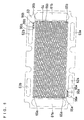
- FIGs. 2 and 3 illustrate a conductive separator in accordance with one embodiment of the present invention.
- a separator 10 has, on the periphery corresponding to the gasket portion 5 of the MEA 6, an oxidant gas inlet-side manifold aperture 11a, an oxidant gas outlet-side manifold aperture 11b, a fuel gas inlet-side manifold aperture 12a, a fuel gas outlet-side manifold aperture 12b, a cooling water inlet-side manifold aperture 13a, and a cooling water outlet-side manifold aperture 13b.
- the separator 10 also has, on a cathode-side, a plurality of gas flow channels 14 which are linear and parallel to each other for supplying an oxidant gas to a cathode and has, on an anode-side, a plurality of parallel gas flow channels 24 for supplying a fuel gas to an anode.
- the gas flow channels 24 have a serpentine shape that is a combination of straight lines and turns. In FIGs. 2 and 3, the portion inside the dashed line and the portion outside the dashed line are to come in contact with the electrode portion 4 and the gasket portion 5 of the MEA 6, respectively.
- connection grooves 16a and 16b are provided on the other side of the separator 10, i.e., on the anode-side of the separator 10.
- connection grooves 26a and 26b are provided on the cathode-side of the separator.
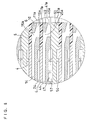
- FIG. 8 is a cross-sectional view of the vital part of a cell stack in which the MEAs are stacked with the separator 10 interposed therebetween.
- the oxidant gas supplied to the inlet-side manifold aperture 11a passes through the connection grooves 16a formed on the anode-side of the separator 10 and the through holes 15a penetrating the separator 10 and reaches the gas flow channels 14 formed on the cathode-side to be supplied to the cathode.
- An excessive gas and a gas generated by the electrode reaction pass from the gas flow channels 14 through the through holes 15b penetrating the separator 10 and the connection grooves 16b formed on the anode-side and reach the outlet-side manifold aperture 11b to be discharged.
- the fuel gas supplied to the inlet-side manifold aperture 12a passes through the connection grooves 26a formed on the cathode-side of the separator 10 and the through holes 25a penetrating the separator 10 and reaches the gas flow channels 24 formed on the anode-side to be supplied to the anode.
- An excessive gas and a gas generated by the electrode reaction pass from the gas flow channels 24 through the through holes 25b penetrating the separator 10 and the connection grooves 26b formed on the cathode-side and reach the outlet-side manifold aperture 12b to be discharged.
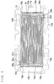
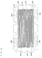
- FIGs. 4 and 5 illustrate a cathode-side conductive separator member having cooling water flow channels formed on the backside thereof
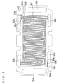
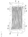
- FIGs. 6 and 7 illustrate an anode-side conductive separator member having cooling water flow channels formed on the backside thereof.
- a cathode-side conductive separator member 40 has an oxidant gas inlet-side manifold aperture 41a, an oxidant gas outlet-side manifold aperture 41b, a fuel gas inlet-side manifold aperture 42a, a fuel gas outlet-side manifold aperture 42b, a cooling water inlet-side manifold aperture 43a, and a cooling water outlet-side manifold aperture 43b.
- the separator member 40 also has, on a cathode-side thereof, a plurality of gas flow channels 44 for oxidant gas, and has through holes 45a and 45b formed at the ends of the gas flow channels 44.
- connection grooves 46a and 46b are provided on the backside of the separator member 40.
- the structure of the separator member 40 is the same as that of the separator 10 except that the separator member 40 has cooling water flow channels 47, of which ends directly communicate with the inlet-side manifold aperture 43a and the outlet-side manifold aperture 43b, instead of the gas flow channels for fuel gas.
- An anode-side conductive separator member 50 has an oxidant gas inlet-side manifold aperture 51a, an oxidant gas outlet-side manifold aperture 51b, a fuel gas inlet-side manifold aperture 52a, a fuel gas outlet-side manifold aperture 52b, a cooling water inlet-side manifold aperture 53a, and a cooling water outlet-side manifold aperture 53b.
- the anode-side conductive separator member 50 has, on an anode side thereof, a plurality of gas flow channels 54 for fuel gas, and has through holes 55a and 55b formed at the ends of the gas flow channels 54.
- connection grooves 56a and 56b are provided on the backside of the separator member 50.
- the separator member 50 also has, on the backside thereof, cooling water flow channels 57, of which ends directly communicate with the inlet-side manifold aperture 53a and the outlet-side manifold aperture 53b.
- FIG. 8 is a cross-sectional view of a cell stack in which the combination of the cathode-side separator member 40 and anode-side separator member 50 is alternately inserted with the separator 10 between the MEAs.
- the oxidant gas supplied to the inlet-side manifold apertures 41a and 51a passes through the connection grooves 46a formed on the backside of the cathode-side separator member 40 and the through holes 45a and reaches the gas flow channels 44 to be supplied to the cathode.
- An excessive gas and a generated gas pass from the gas flow channels 44 through the through holes 45b and the connection grooves 46b and reach the outlet-side manifold aperture 41b to be discharged.
- the fuel gas supplied to the inlet-side manifold aperture 42a and 52a passes through the connection grooves 56a formed on the backside of the anode-side separator member 50 and the through holes 55a and reaches the gas flow channels 54 to be supplied to the anode.
- An excessive gas and a generated gas pass from the gas flow channels 54 through the through holes 55b and the connection grooves 56b and reach the outlet-side manifold aperture 52b to be discharged.
- the cooling water supplied to the inlet-side manifold apertures 43a and 53a passes through the serpentine cooling water flow channels 47 and 57 and is discharged from the outlet-side manifold apertures 43b and 53b. In this manner, the cooling water cools fuel cells from the backsides of the cathode-side separator member 40 and anode-side separator member 50.
- water is generally and conveniently used, but an antifreezing solution such as ethylene glycol may be used.
- FIG. 14 is a cross-sectional view of the vital part of a cell stack comprising conventional separators 100.
- the separator 100 has, on a cathode side thereof, a gas flow channel for oxidant gas 104 communicating with an oxidant gas manifold aperture 111 and has, on an anode side thereof, a gas flow channel for fuel gas 114 communicating with a fuel gas manifold aperture.
- a gasket 5 of an MEA 6 may be pressed to fall into the channel 104 in the vicinity of the manifold aperture 111 due to the clamping pressure.
- the gasket 5 and an adjoining portion of an electrode portion 4 become deformed toward the channel 104 as shown by the dotted line of FIG. 14, thereby creating a clearance 7 on the anode side between the deformed electrode portion 4' and gasket 5' and the adjoining separator 100.
- the clearance 7 communicates with the gas flow channel for fuel gas 114, the fuel gas is mixed with the oxidant gas from the manifold aperture 111.
- the gas flow channel for oxidant gas 14 of the separator 10 communicates with the manifold aperture 11a through the through hole 15a and the connection groove 16a formed on the anode-side, as shown in FIG. 8. Even if the MEA is pressed down into the gas flow channel 14, the gasket 5 of the MEA is received by the portion of the separator 10 without any channel or groove between the through hole 15a and the manifold aperture 11a.
- the gasket 5 does not fall into the gas flow channel for oxidant gas 14 on the cathode side of the separator 10 in the vicinity of the manifold aperture 11a, so that such a clearance as to connect the gas flow channel for fuel gas 24 with the oxidant gas manifold aperture 11a is not created on the anode side between the gasket and the adjoining separator.
- the clearance communicates with the oxidant gas manifold aperture or gas flow channel for oxidant gas, so that no mixing of the oxidant gas with the fuel gas occurs.
- the present invention causes no mixing of the oxidant gas with the fuel gas also in the case of the gasket falling into the fuel gas channel.
- FIGs. 9 and 10 illustrate a cathode-side conductive separator member having cooling water flow channels formed on the backside thereof
- FIGs. 11 and 12 illustrate an anode-side conductive separator member having cooling water flow channels formed on the backside thereof.
- a cathode-side conductive separator member 60 has an oxidant gas inlet-side manifold aperture 61a, an oxidant gas outlet-side manifold aperture 61b, a fuel gas inlet-side manifold aperture 62a, a fuel gas outlet-side manifold aperture 62b, a cooling water inlet-side manifold aperture 63a, and a cooling water outlet-side manifold aperture 63b.
- the separator member 60 also has, on a cathode side thereof, a plurality of gas flow channels 64 for oxidant gas, and has through holes 65a and 65b formed at the ends of the gas flow channels 64.
- the separator member 60 further has through holes 95a and 95b for fuel gas communicating with through holes for fuel gas 75a and 75b, respectively, of an anode-side separator member 70 that will be described later.
- the separator member 60 In order to connect the through holes 95a and 95b for fuel gas with the fuel gas inlet-side manifold aperture 62a and the fuel gas outlet-side manifold aperture 62b, respectively, the separator member 60 still further has connection grooves for fuel gas 96a and 96b on the cathode-side.
- the separator member 60 has, on the backside thereof, serpentine cooling water flow channels 67, of which inlet-side end and outlet-side end communicate with the inlet-side manifold aperture 63a and the outlet-side manifold aperture 63b, respectively.
- An anode-side conductive separator member 70 has an oxidant gas inlet-side manifold aperture 71a, an oxidant gas outlet-side manifold aperture 71b, a fuel gas inlet-side manifold aperture 72a, a fuel gas outlet-side manifold aperture 72b, a cooling water inlet-side manifold aperture 73a, and a cooling water outlet-side manifold aperture 73b.
- the anode-side conductive separator member 70 also has, on an anode side thereof, a plurality of gas flow channels 74 for fuel gas, and has through holes for fuel gal 75a and 75b formed at the ends of the gas flow channels 74.
- the separator member 70 further has through holes for oxidant gas 85a and 85b communicating with the through holes for oxidant gas 65a and 65b, respectively, of the cathode-side separator member 60.
- the separator member 70 In order to connect the through holes for oxidant gas 85a and 85b with the oxidant gas inlet-side manifold aperture 71a and the oxidant gas outlet-side manifold aperture 71b, respectively, the separator member 70 still further has connection grooves for oxidant gas 86a and 86b on the anode side.
- the separator member 70 has, on the backside thereof, serpentine cooling water flow channels 77, of which inlet-side end and outlet-side end communicate with the inlet-side manifold aperture 73a and the outlet-side manifold aperture 73b, respectively.
- FIG. 13 is a cross-sectional view of a cell stack in which the combination of the cathode-side separator member 60 and anode-side separator member 70 is alternately inserted with the separator 10 between the MEAs.
- the oxidant gas supplied to the inlet-side manifold apertures 61a and 71a passes through the connection grooves 86a formed on the anode-side of the anode-side separator member 70 and the through holes 85a and 65a and reaches the gas flow channels 64 to be supplied to the cathode.
- An excessive gas and a generated gas pass from the gas flow channels 64 through the through holes 65b and 85b and the connection grooves 86b and reach the outlet-side manifold aperture 71b to be discharged.
- the fuel gas supplied to the inlet-side manifold aperture 62a of the cathode-side separator member 60 passes through the connection grooves 96a and the through holes 95a and 75a and reaches the gas flow channels 74 formed on the anode-side of the anode-side separator member 70 to be supplied to the anode.
- An excessive gas and a generated gas pass from the gas flow channels 74 through the through holes 75b and 95b and the connection grooves 96b and reach the outlet-side manifold aperture 62b to be discharged.
- the cooling water supplied to the inlet-side manifold apertures 63a and 73a passes through the serpentine cooling water channels 67 and 77 and is discharged from the outlet-side manifold apertures 63b and 73b. In this manner, the cooling water cools fuel cells from the backsides of the cathode-side separator member 60 and anode-side separator member 70.
- cooling water flow channels were formed on opposing sides of two separator members in the foregoing embodiments, they may be formed only on one separator member.
- the present invention can prevent a cross leak of two different gases from occurring at edges of the contacting portion of the conductive separator and the gasket of the MEA in the vicinity of a manifold aperture.
- a plurality of parallel gas flow channels for supplying the oxidant gas or the fuel gas were formed, but just one gas flow channel may be formed. Similarly, this applies to the number of cooling water flow channel. In the case of one gas flow channel, the number of inlet-side through hole, outlet-side through hole, inlet-side connection groove and outlet-side connection groove may be just one.
- one gasket covered both sides of the electrolyte membrane exposed to outside, but two gaskets may be used to cover each side of the electrolyte membrane exposed to outside.
- a conductive carbon powder having an average particle size of 30 nm (Ketgenblack EC, manufactured by Akzochimie in Holland) was allowed to carry platinum particles having an average particle size of about 30 ⁇ in a weight ratio of 75:25, which gave an electrode catalyst powder.
- a dispersion of this catalyst powder in isopropanol was mixed with a dispersion of perfluorocarbon sulfonic acid powder in ethyl alcohol represented by the following chemical formula to prepare a paste.
- This paste was printed on one side of a 250 ⁇ m thick carbon fiber nonwoven fabric by screen printing to form an electrode catalyst layer.
- the electrode catalyst layer was formed so as to contain 0.5 mg/cm 2 platinum and 1.2 mg/cm 2 perfluorocarbon sulfonic acid.
- a cathode and an anode thus produced were bonded, by hot pressing, to both sides of the center part of a hydrogen-ion conductive polymer electrolyte membrane having an area slightly larger than that of the electrode in such a manner that each of the printed catalyst layers of the electrodes was in contact with the electrolyte membrane.
- MEA membrane electrode assembly
- the structure of this MEA is shown in FIG. 1, in which numeral 6 represents the MEA, numeral 4 the electrode portion, and numeral 5 the gasket portion arranged on the outer periphery of the electrode portion 4.
- a polymer electrolyte fuel cell as shown in FIG. 8 was assembled using the separators 10, 40 and 50 as shown in FIGs. 2 to 7.
- separators were produced by processing a plate of isotropic graphite having a thickness of 2 mm, a height of 130 mm and a width of 260 mm with the following specifications.
- the gas flow channels for oxidant gas 14 and 44 were formed to have a width of about 2 mm and a pitch of 2.9 mm in a 20 cm ⁇ 9 cm area at the center of a cathode-side of the graphite plate.
- the gas flow channels for fuel gas 24 and 54 were formed to have a serpentine shape with the same width and pitch on an anode-side of the plate.
- the cooling water flow channels 47 and 57 were produced to have a width of about 2 mm and a pitch of 2.9 mm.
- the cathode-side gas flow channels 14 and anode-side gas flow channels 24 were formed with their center lines of the linear part exactly corresponding to each other, in order to prevent excessive shearing force from being applied to the electrodes.
- the combination of the separator members 40 and 50 was inserted every two unit cells to provide the polymer electrolyte fuel cell with cooling sections for flowing cooling water therein.
- two kinds of the separator members 40 and 50 having cooling water flow channels were bonded to each other with a sealant (#1211, Liquid Gasket of Solventless Silicon & Sag Type, manufactured by Three Bond Co., Ltd) in such a manner that their sides having the cooling water flow channels faced each other.
- a sealant #1211, Liquid Gasket of Solventless Silicon & Sag Type, manufactured by Three Bond Co., Ltd
- the gasket bonded to the MEA was used to air-tightly seal the combination of the separator and the MEA, while the sealant, #1211, was used to air-tightly seal the combination of
- the MEAs thus produced were stacked with the above-described separators interposed therebetween to form a stack of 50 cells, and the resultant cell stack was clamped with current collector plates, insulating plates and stainless steel end plates, using clamping rods with a pressure of 10 kgf/cm 2 .
- a polymer electrolyte fuel cell was assembled in the same manner as in Example 1 except for the use of the combination of the separator members 60 and 70 for forming cooling water flow channels. While this polymer electrolyte fuel cell was held at 75 °C, a hydrogen gas humidified and heated to have a dew point of 70 °C was supplied to the anode and air humidified and heated to have a dew point of 65 °C was supplied to the cathode. The results indicate that the fuel cell of this example has almost the same performance as that of Example 1.
- the present invention can prevent a cross leak of two different gases from occurring at edges of the contacting portion of the conductive separator and the gasket of the MEA in the vicinity of a manifold aperture.
Landscapes
- Chemical & Material Sciences (AREA)
- Life Sciences & Earth Sciences (AREA)
- Engineering & Computer Science (AREA)
- Manufacturing & Machinery (AREA)
- Sustainable Development (AREA)
- Sustainable Energy (AREA)
- Chemical Kinetics & Catalysis (AREA)
- Electrochemistry (AREA)
- General Chemical & Material Sciences (AREA)
- Composite Materials (AREA)
- Fuel Cell (AREA)
Applications Claiming Priority (2)
| Application Number | Priority Date | Filing Date | Title |
|---|---|---|---|
| JP2000399057A JP3596761B2 (ja) | 2000-12-27 | 2000-12-27 | 高分子電解質型燃料電池 |
| JP2000399057 | 2000-12-27 |
Publications (3)
| Publication Number | Publication Date |
|---|---|
| EP1220347A2 true EP1220347A2 (de) | 2002-07-03 |
| EP1220347A3 EP1220347A3 (de) | 2004-05-12 |
| EP1220347B1 EP1220347B1 (de) | 2008-07-30 |
Family
ID=18863904
Family Applications (1)
| Application Number | Title | Priority Date | Filing Date |
|---|---|---|---|
| EP01310790A Expired - Lifetime EP1220347B1 (de) | 2000-12-27 | 2001-12-21 | Polymerelektrolyt-Brennstoffzellenstapel |
Country Status (4)
| Country | Link |
|---|---|
| US (2) | US6740443B2 (de) |
| EP (1) | EP1220347B1 (de) |
| JP (1) | JP3596761B2 (de) |
| DE (1) | DE60135081D1 (de) |
Cited By (6)
| Publication number | Priority date | Publication date | Assignee | Title |
|---|---|---|---|---|
| WO2002039528A3 (en) * | 2000-11-08 | 2003-02-27 | Global Thermoelectric Inc | Fuel cell interconnect |
| WO2004013923A1 (de) * | 2002-07-31 | 2004-02-12 | Sfc Smart Fuel Cell Ag | Plattenelemente für brennstoffzellenstacks |
| EP1469542A1 (de) * | 2003-04-09 | 2004-10-20 | Matsushita Electric Industrial Co., Ltd. | Polymerelektrolytmembran-Brennstoffzelle |
| WO2005086273A1 (en) * | 2004-03-03 | 2005-09-15 | Ird Fuel Cells A/S | Dual function, bipolar separator plates for fuel cells |
| WO2005055348A3 (en) * | 2003-11-21 | 2005-11-10 | Ird Fuel Cells As | Modified gas outlet for improved reactant handling in fuel cell separator plates |
| US7309542B2 (en) | 2003-07-09 | 2007-12-18 | Honda Motor Co., Ltd. | Membrane electrode assembly and fuel cell |
Families Citing this family (29)
| Publication number | Priority date | Publication date | Assignee | Title |
|---|---|---|---|---|
| US7226688B2 (en) | 1999-09-10 | 2007-06-05 | Honda Motor Co., Ltd. | Fuel cell |
| US7062443B2 (en) * | 2000-08-22 | 2006-06-13 | Silverman Stephen E | Methods and apparatus for evaluating near-term suicidal risk using vocal parameters |
| JP2002298872A (ja) * | 2001-03-30 | 2002-10-11 | Isuzu Motors Ltd | 燃料電池用セパレータ及び燃料電池 |
| JP4105421B2 (ja) * | 2001-10-31 | 2008-06-25 | 株式会社日立製作所 | 固体高分子型燃料電池用電極及びそれを用いた固体高分子型燃料電池並びに発電システム |
| US20030211376A1 (en) | 2002-03-26 | 2003-11-13 | Matsushita Electric Industrial Co., Ltd. | Polymer electrolyte fuel cell, method of manufacturing the same and inspection method therefor |
| SE523665C2 (sv) * | 2002-09-20 | 2004-05-11 | Volvo Technology Corp | Bränslecell och bränslecellsstack |
| CN1536698B (zh) | 2003-04-02 | 2010-12-15 | 松下电器产业株式会社 | 燃料电池用电解质膜结构、mea结构及燃料电池 |
| US7745063B2 (en) * | 2004-04-27 | 2010-06-29 | Panasonic Corporation | Fuel cell stack |
| US7955491B2 (en) * | 2004-09-14 | 2011-06-07 | Honda Motor Co., Ltd. | Methods, devices, and infrastructure systems for separating, removing, compressing, and generating hydrogen |
| JP4562501B2 (ja) * | 2004-11-25 | 2010-10-13 | 本田技研工業株式会社 | 燃料電池 |
| JP4692001B2 (ja) * | 2005-02-08 | 2011-06-01 | トヨタ自動車株式会社 | 燃料電池のセパレータ |
| JP4244041B2 (ja) * | 2005-04-07 | 2009-03-25 | シャープ株式会社 | リチウムイオン二次電池及びその製造方法 |
| US7833645B2 (en) | 2005-11-21 | 2010-11-16 | Relion, Inc. | Proton exchange membrane fuel cell and method of forming a fuel cell |
| US20080032174A1 (en) * | 2005-11-21 | 2008-02-07 | Relion, Inc. | Proton exchange membrane fuel cells and electrodes |
| JP4607827B2 (ja) * | 2006-01-11 | 2011-01-05 | 三星エスディアイ株式会社 | 燃料電池システム |
| US7927758B2 (en) * | 2006-01-11 | 2011-04-19 | Samsung Sdi Co., Ltd. | Gasket being capable of measuring voltage and fuel cell system having the same |
| FR2902930B1 (fr) * | 2006-06-21 | 2009-11-27 | Commissariat Energie Atomique | Plaque bipolaire pour pile a combustible, et pile a combustible a distribution de fluide amelioree mettant en oeuvre de telles plaques |
| JP2008166063A (ja) * | 2006-12-27 | 2008-07-17 | Matsushita Electric Ind Co Ltd | 燃料電池 |
| JP5082467B2 (ja) * | 2007-01-29 | 2012-11-28 | トヨタ自動車株式会社 | 燃料電池、および、燃料電池を構成するセパレータ |
| US8026020B2 (en) | 2007-05-08 | 2011-09-27 | Relion, Inc. | Proton exchange membrane fuel cell stack and fuel cell stack module |
| KR100830980B1 (ko) * | 2007-05-28 | 2008-05-20 | 삼성에스디아이 주식회사 | 연료 전지용 스택 |
| US9293778B2 (en) | 2007-06-11 | 2016-03-22 | Emergent Power Inc. | Proton exchange membrane fuel cell |
| US8003274B2 (en) | 2007-10-25 | 2011-08-23 | Relion, Inc. | Direct liquid fuel cell |
| JP5214372B2 (ja) * | 2008-08-27 | 2013-06-19 | 本田技研工業株式会社 | 燃料電池 |
| US20100285386A1 (en) * | 2009-05-08 | 2010-11-11 | Treadstone Technologies, Inc. | High power fuel stacks using metal separator plates |
| KR20130073985A (ko) * | 2010-11-24 | 2013-07-03 | 유티씨 파워 코포레이션 | 전지 스택 어셈블리의 단부에 클로킹 방지 특징부를 갖는 연료 전지 어셈블리 |
| USD844562S1 (en) * | 2016-10-05 | 2019-04-02 | General Electric Company | Fuel cell |
| DE102021203965A1 (de) * | 2021-04-21 | 2022-10-27 | Cellcentric Gmbh & Co. Kg | Bipolarplatte für einen Brennstoffzellenstapel |
| DE102023101599A1 (de) * | 2023-01-24 | 2024-07-25 | MTU Aero Engines AG | Bipolarplatte für eine brennstoffzelle |
Family Cites Families (9)
| Publication number | Priority date | Publication date | Assignee | Title |
|---|---|---|---|---|
| RU2174728C2 (ru) * | 1994-10-12 | 2001-10-10 | Х Пауэр Корпорейшн | Топливный элемент, использующий интегральную технологию пластин для распределения жидкости |
| US5514487A (en) * | 1994-12-27 | 1996-05-07 | Ballard Power Systems Inc. | Edge manifold assembly for an electrochemical fuel cell stack |
| JPH08222237A (ja) * | 1995-02-14 | 1996-08-30 | Aisin Aw Co Ltd | 燃料電池用セパレータ |
| JPH0935726A (ja) | 1995-07-18 | 1997-02-07 | Tanaka Kikinzoku Kogyo Kk | 燃料電池用ガスプレート、冷却プレート及び燃料電池 |
| US5858867A (en) * | 1996-05-20 | 1999-01-12 | Mosel Vitelic, Inc. | Method of making an inverse-T tungsten gate |
| US6017648A (en) * | 1997-04-15 | 2000-01-25 | Plug Power, L.L.C. | Insertable fluid flow passage bridgepiece and method |
| JP4066536B2 (ja) * | 1998-10-28 | 2008-03-26 | アイシン精機株式会社 | ガスマニホールド一体型セパレータ及び固体高分子電解質型燃料電池 |
| US6387558B1 (en) * | 1999-02-18 | 2002-05-14 | Toyota Jidosha Kabusiki Kaisha | Fuel cell, separator for the same and method for distributing gas in fuel cell |
| JP4809519B2 (ja) | 1999-09-10 | 2011-11-09 | 本田技研工業株式会社 | 燃料電池 |
-
2000
- 2000-12-27 JP JP2000399057A patent/JP3596761B2/ja not_active Expired - Lifetime
-
2001
- 2001-12-21 DE DE60135081T patent/DE60135081D1/de not_active Expired - Lifetime
- 2001-12-21 US US10/023,907 patent/US6740443B2/en not_active Expired - Lifetime
- 2001-12-21 EP EP01310790A patent/EP1220347B1/de not_active Expired - Lifetime
-
2004
- 2004-05-10 US US10/841,557 patent/US7521143B2/en not_active Expired - Lifetime
Cited By (13)
| Publication number | Priority date | Publication date | Assignee | Title |
|---|---|---|---|---|
| WO2002039528A3 (en) * | 2000-11-08 | 2003-02-27 | Global Thermoelectric Inc | Fuel cell interconnect |
| US6855451B2 (en) | 2000-11-08 | 2005-02-15 | Fuelcell Energy, Ltd. | Electrochemical cell interconnect |
| WO2004013923A1 (de) * | 2002-07-31 | 2004-02-12 | Sfc Smart Fuel Cell Ag | Plattenelemente für brennstoffzellenstacks |
| EP1394877A1 (de) * | 2002-07-31 | 2004-03-03 | SFC Smart Fuel Cell AG | Plattenelemente für Brennstoffzellenstacks |
| US7662499B2 (en) | 2002-07-31 | 2010-02-16 | Sfc Smart Fuel Cell Ag | Plate elements for fuel cell stacks |
| CN100463276C (zh) * | 2003-04-09 | 2009-02-18 | 松下电器产业株式会社 | 高分子电解质型燃料电池 |
| EP1469542A1 (de) * | 2003-04-09 | 2004-10-20 | Matsushita Electric Industrial Co., Ltd. | Polymerelektrolytmembran-Brennstoffzelle |
| US7678490B2 (en) | 2003-04-09 | 2010-03-16 | Panasonic Corporation | Polymer electrolyte fuel cell |
| US7309542B2 (en) | 2003-07-09 | 2007-12-18 | Honda Motor Co., Ltd. | Membrane electrode assembly and fuel cell |
| DE102004032907B4 (de) * | 2003-07-09 | 2008-06-19 | Honda Motor Co., Ltd. | Membranelektrodenanordnung und Brennstoffzelle |
| WO2005055348A3 (en) * | 2003-11-21 | 2005-11-10 | Ird Fuel Cells As | Modified gas outlet for improved reactant handling in fuel cell separator plates |
| WO2005086273A1 (en) * | 2004-03-03 | 2005-09-15 | Ird Fuel Cells A/S | Dual function, bipolar separator plates for fuel cells |
| US7615308B2 (en) | 2004-03-03 | 2009-11-10 | Ird Fuel Cells A/S | Dual function, bipolar separator plates for fuel cells |
Also Published As
| Publication number | Publication date |
|---|---|
| US7521143B2 (en) | 2009-04-21 |
| US20040209141A1 (en) | 2004-10-21 |
| US20020119359A1 (en) | 2002-08-29 |
| US6740443B2 (en) | 2004-05-25 |
| EP1220347A3 (de) | 2004-05-12 |
| JP2002203578A (ja) | 2002-07-19 |
| JP3596761B2 (ja) | 2004-12-02 |
| EP1220347B1 (de) | 2008-07-30 |
| DE60135081D1 (de) | 2008-09-11 |
Similar Documents
| Publication | Publication Date | Title |
|---|---|---|
| EP1220347B1 (de) | Polymerelektrolyt-Brennstoffzellenstapel | |
| JP3460346B2 (ja) | 固体高分子電解質型燃料電池 | |
| US7014940B2 (en) | High-polymer electrolyte fuel cell | |
| CN101395751B (zh) | 电池层叠体和设有所述电池层叠体的燃料电池 | |
| US7390586B2 (en) | Fuel cell stacks of alternating polarity membrane electrode assemblies | |
| US7678490B2 (en) | Polymer electrolyte fuel cell | |
| WO2009144871A1 (ja) | 燃料電池 | |
| JP4134731B2 (ja) | 燃料電池のシール構造 | |
| US8003273B2 (en) | Polymer electrolyte fuel cell and fuel cell sealing member for the same | |
| US10297811B2 (en) | Fuel cell stack | |
| JP4051076B2 (ja) | 高分子電解質型燃料電池 | |
| US7846613B2 (en) | Fuel cell with separator having a ridge member | |
| US7790326B2 (en) | Fuel cell and separator for fuel cell | |
| JP2002352817A (ja) | 高分子電解質型燃料電池 | |
| US10497948B2 (en) | Fuel cell stack with asymmetrical bipolar plates | |
| JP5143336B2 (ja) | 高分子電解質型燃料電池 | |
| JP2003123801A (ja) | 高分子電解質型積層燃料電池 | |
| JP2001126743A (ja) | 高分子電解質型燃料電池 | |
| US20220077485A1 (en) | Fuel Cell | |
| JP2001167789A (ja) | 高分子電解質型燃料電池 | |
| JP4397603B2 (ja) | 高分子電解質型燃料電池 | |
| JP3496819B2 (ja) | 高分子電解質型燃料電池 | |
| JP2004349015A (ja) | 高分子電解質型燃料電池 | |
| WO2025204372A1 (ja) | 燃料電池スタック | |
| CN101233639A (zh) | 燃料电池 |
Legal Events
| Date | Code | Title | Description |
|---|---|---|---|
| PUAI | Public reference made under article 153(3) epc to a published international application that has entered the european phase |
Free format text: ORIGINAL CODE: 0009012 |
|
| AK | Designated contracting states |
Kind code of ref document: A2 Designated state(s): AT BE CH CY DE DK ES FI FR GB GR IE IT LI LU MC NL PT SE TR |
|
| AX | Request for extension of the european patent |
Free format text: AL;LT;LV;MK;RO;SI |
|
| PUAL | Search report despatched |
Free format text: ORIGINAL CODE: 0009013 |
|
| AK | Designated contracting states |
Kind code of ref document: A3 Designated state(s): AT BE CH CY DE DK ES FI FR GB GR IE IT LI LU MC NL PT SE TR |
|
| AX | Request for extension of the european patent |
Extension state: AL LT LV MK RO SI |
|
| RIC1 | Information provided on ipc code assigned before grant |
Ipc: 7H 01M 8/02 A Ipc: 7H 01M 8/24 B |
|
| 17P | Request for examination filed |
Effective date: 20041109 |
|
| AKX | Designation fees paid |
Designated state(s): DE FR GB |
|
| GRAP | Despatch of communication of intention to grant a patent |
Free format text: ORIGINAL CODE: EPIDOSNIGR1 |
|
| GRAS | Grant fee paid |
Free format text: ORIGINAL CODE: EPIDOSNIGR3 |
|
| GRAA | (expected) grant |
Free format text: ORIGINAL CODE: 0009210 |
|
| AK | Designated contracting states |
Kind code of ref document: B1 Designated state(s): DE FR GB |
|
| REG | Reference to a national code |
Ref country code: GB Ref legal event code: FG4D |
|
| REF | Corresponds to: |
Ref document number: 60135081 Country of ref document: DE Date of ref document: 20080911 Kind code of ref document: P |
|
| RAP2 | Party data changed (patent owner data changed or rights of a patent transferred) |
Owner name: PANASONIC CORPORATION |
|
| PLBE | No opposition filed within time limit |
Free format text: ORIGINAL CODE: 0009261 |
|
| STAA | Information on the status of an ep patent application or granted ep patent |
Free format text: STATUS: NO OPPOSITION FILED WITHIN TIME LIMIT |
|
| 26N | No opposition filed |
Effective date: 20090506 |
|
| REG | Reference to a national code |
Ref country code: FR Ref legal event code: PLFP Year of fee payment: 15 |
|
| REG | Reference to a national code |
Ref country code: FR Ref legal event code: PLFP Year of fee payment: 16 |
|
| REG | Reference to a national code |
Ref country code: FR Ref legal event code: PLFP Year of fee payment: 17 |
|
| PGFP | Annual fee paid to national office [announced via postgrant information from national office to epo] |
Ref country code: GB Payment date: 20201210 Year of fee payment: 20 Ref country code: DE Payment date: 20201208 Year of fee payment: 20 Ref country code: FR Payment date: 20201112 Year of fee payment: 20 |
|
| REG | Reference to a national code |
Ref country code: DE Ref legal event code: R071 Ref document number: 60135081 Country of ref document: DE |
|
| REG | Reference to a national code |
Ref country code: GB Ref legal event code: PE20 Expiry date: 20211220 |
|
| PG25 | Lapsed in a contracting state [announced via postgrant information from national office to epo] |
Ref country code: GB Free format text: LAPSE BECAUSE OF EXPIRATION OF PROTECTION Effective date: 20211220 |