EP1220406A2 - Boítier de sortie ou d'interconnection - Google Patents
Boítier de sortie ou d'interconnection Download PDFInfo
- Publication number
- EP1220406A2 EP1220406A2 EP01124200A EP01124200A EP1220406A2 EP 1220406 A2 EP1220406 A2 EP 1220406A2 EP 01124200 A EP01124200 A EP 01124200A EP 01124200 A EP01124200 A EP 01124200A EP 1220406 A2 EP1220406 A2 EP 1220406A2
- Authority
- EP
- European Patent Office
- Prior art keywords
- cover
- box according
- contact
- space
- box
- Prior art date
- Legal status (The legal status is an assumption and is not a legal conclusion. Google has not performed a legal analysis and makes no representation as to the accuracy of the status listed.)
- Granted
Links
Images


Classifications
-
- H—ELECTRICITY
- H02—GENERATION; CONVERSION OR DISTRIBUTION OF ELECTRIC POWER
- H02B—BOARDS, SUBSTATIONS OR SWITCHING ARRANGEMENTS FOR THE SUPPLY OR DISTRIBUTION OF ELECTRIC POWER
- H02B1/00—Frameworks, boards, panels, desks, casings; Details of substations or switching arrangements
- H02B1/26—Casings; Parts thereof or accessories therefor
- H02B1/46—Boxes; Parts thereof or accessories therefor
- H02B1/48—Mounting of devices therein
-
- H—ELECTRICITY
- H02—GENERATION; CONVERSION OR DISTRIBUTION OF ELECTRIC POWER
- H02G—INSTALLATION OF ELECTRIC CABLES OR LINES, OR OF COMBINED OPTICAL AND ELECTRIC CABLES OR LINES
- H02G5/00—Installations of bus-bars
- H02G5/06—Totally-enclosed installations, e.g. in metal casings
- H02G5/08—Connection boxes therefor
Definitions
- the invention relates to an outgoing or junction box according to the preamble of claim 1.
- a tap-off unit is shown and described in EP 0 555 665 B1, which, as shown there in FIGS. 11 to 15, has two cover sections which can be opened depending on each other.
- the first Lid section is operatively connected to a locking device.
- the first lid section can only be opened if the second one already is open.
- the first cover section automatically disconnects the power supply when opened.
- An NH fuse is arranged below the second cover section, pulled out of the fuse base when opening the second cover becomes.
- the font mentioned shows a tap-off unit in FIG. 1 with a single cover, a break contact device with break contact points and a break contact space.
- the isolating contact device acts as Safety device, which when working with an open lid for zero voltage provides.
- the object of the invention is a box according to the preamble of the claim 1 to create that is safe and harmless and high power availability having.
- the safety function is essentially achieved in that the outgoing or junction box one, only located above the isolating contact space, has the first cover with contact bridges arranged thereon.
- the contact bridges which can be implemented in any way, as long as they galvanically interrupt the power supply, the geometric Form is not critical, can be on the tap or junction box also work in areas that are not finger-safe. That is also the one Case when terminal blocks or fuse elements are replaced have to. It is particularly advantageous if the isolating contact device is used other safety functions, such as a mechanical locking function can be combined.
- connection space By arranging two lids, there is basically a division into an isolating contact space and a connection space. If the connection space can be closed with a second lid, which is independent of a first one The lid can still be opened without inevitable actuation of the Disconnect contact device in which connection space is worked.
- the tap-off or junction box only becomes particularly secure when the connection compartment only for protection and connection elements according to the degree of protection IP20 (finger safe) is provided.
- a particularly easy to use, safe and easy to manufacture embodiment results if the second cover comprises a first bearing point, which is connected to the basic housing, and the second cover a second Bearing includes a second end of the tap or junction box is assigned if the first bearing of a first - the second Face opposite - face is assigned, creating two different Opening or rotation directions result.
- Each cover can have two cover surfaces to rest on the connection compartment and be formed on the isolating contact space.
- the cover surface on the connection space of the first cover can be window-like to have left
- the second cover can be connected to the first cover via a second bearing so that the second cover either completely above the isolating contact space and the connection space or only rests above the connection compartment and can be opened.
- a construction is favorable if the separation function and possible locking functions what with the opening of the second lid triggered is particularly easy to use.
- the switching status of the devices is visible from the outside when the cover flap is transparent.
- the first cover is designed such that it must be opened with the second cover, so that the connection elements be de-energized in the terminal compartment in any case.
- the fastening and locking means and locking means operatively connected to the fastening and locking means comprises, wherein the fastening and locking means on the rail channel are attachable.
- the fixation of the tap-off or junction box is improved if the Outlet or junction box includes fasteners, the fasteners are attachable to the rail channel.
- the tap or junction box has at least one cable entry, but preferably only on one side.
- the isolating contact space is securely closed when the first cover comprises first locking means and / or the first locking means the basic housing can be locked on at least one counter-lock.
- connection compartment is securely closed when the second cover is closed has second locking means, the second locking means in a favorable manner can be locked on the first cover and / or on the basic housing.
- the covers have primarily the function of the individual cover of the respective Connecting rooms.
- the lids also have cover surfaces for both Terminal spaces can be formed so that they are above both Rooms.
- at least the first cover has the Function of voltage isolation when opening. This functions the lid can be meaningfully combined with each other.
- An advantageous embodiment results when the first cover is hinge-like with the second cover is connected that both covers form two layers arranged one above the other.
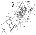
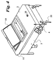
- Fig. 1 shows an outgoing or junction box 3 for a busbar trunking system for the distribution of electrical energy.
- Busbar trunking system on which the tap-off or junction box can be placed, is shown and described in DE 34 37 586 A1.
- the busbar trunking system includes a rail channel with busbars and outlets in it, on which the outgoing or shown in Figures 1 to 4 Junction box is connectable.
- the outlet or junction box 3 has contact plugs in a known manner that can be contacted at the points of departure on the conductor rails.
- the contact plug like the tap-off unit, is described in the publication is, with a disconnect contact device arranged in a disconnect contact space 6 7 electrically connected.
- the firmly connected with a first cover 1 Contact bridges bridge the isolating contact device 7 electrically only with the lid closed. This makes sense when opening of the first cover 1, the power supply to the on the outgoing or Junction box 3 connected electrical consumers interrupted is.
- the outlet or junction box 3 can be removed from the busbar trunking system without being between the contact plugs and the busbars arcing, which is sometimes very dangerous.
- a connection room 12 as can be seen in FIGS. 1 and 3, are protective and Connection elements 8, such as fuse elements 9 or terminals 10, are present, assigned to different consumers or consumer groups are.
- the securing elements 9 or terminals 10 are on top-hat rails 30 assembled.
- the tap or junction box 3 has one, according to the invention, essentially only the first cover 1 covering the isolating contact space 6 (cover surface 15) with contact bridges arranged thereon. Furthermore, the first one Cover 1 designed so that it inevitably only with the second cover 2 open or close.
- connection space 1 is separated by a second cover 2 the first cover 2 can be opened or closed in a flap-like manner, can be closed.
- the second cover 2 has a first bearing point (hinge) 4, which is connected to the basic housing 5.
- both lids are over a second bearing 11 articulated together.
- the bearing 11 is assigned to a second end face 14 of the box, as shown in FIG. 1.
- the Box 3 comprises a first end face 13 and a second opposite one End face 14.
- the first bearing 4 is assigned to the first end face 13.
- the second cover 2 has two cover surfaces for each of the rooms. With the shown The two lids are arranged one above the other in their entire length to lie.
- the top surface 15 of the first lid has the Terminal compartment 12 a window-like terminal compartment opening 17.
- the second cover 2 is either completely above the isolating contact space 6 and the connection space 12, as shown in FIG. 3, or it is only above the connection space 12 foldable, as Fig. 1 shows.
- a first bearing point 4 (hinge) to the basic housing is on the first cover 1 arranged.
- a second bearing point (hinge) 11 connects the first to the second lid 2, as shown in Figures 1 and 3.
- the bearings 4 and 11 are mutually arranged.
- the second cover 2 can with the first cover 1 opened and closed like a single lid, like a comparison of Figures 2 and 3 shows.
- the second cover 2 has a cutout 18 to lie directly above the first cover 1 in the closed state comes.
- the recess 18 lends itself to the arrangement of a handle 27.
- the handle 27 is arranged on the second cover 2.
- the Handle 27 mounted recessed in the box, the handle in one piece with an insulating body 28 is connected to hold the contact bridges 29.
- connection terminal 12 transparent lid flap 19 for direct access to operating levers, Shift knobs and similar parts arranged.
- the first cover 1 is shown in more detail in the document EP 0 555 665 B1 and explained locking device, wherein the locking device Fastening and locking means 20 and with the fastening and locking means 20 has locking means 21 operatively connected.
- the Fastening and locking means 20 can be fastened to the rail channel
- the fastening and locking device consists, like the figures of the Document EP 0 555 665 B1 show a rotatable around its longitudinal axis Axis, which is a fastening and corresponding to the rail channel Locking element (fastening and locking means 20) and one with the corresponding locking member receives the second contact member.
- the fastening and locking device has a fastening pin for Holding the tap-off box and a locking bolt on, which is an illegal Prevention of the tap-off box on a rail channel.
- the axis is arranged on the bottom and is axially under spring action.
- the fastening and Locking device can only be operated within the tap-off unit.
- the fastening pin is provided with at least one slope.
- the locking part blocks the closing of the first cover 1 when not on the rail channel attached tap-off box.
- the locking part consists of an integrally molded Lock pin and also integrally molded and essentially handling section connected to the locking pin, the Rotational movement of the locking part is limited by a stop.
- the fastening and locking element is in FIG. 3 with the reference symbol 20 marked.
- other fasteners are on the box 3 arranged.
- Further fastening elements for rail channel fastening are marked with 22.
- the box 3 has a cable bushing 23 on one side.
- she consists essentially of metal.
- the second cover 2 or here the cover surface 16 for the connection space has second locking means 25, which are shown in Figures 1 and 2.
- the second locking means 25 can be locked on the top surface 15 of the first lid.
- the hinge-like connection of the lids to one another makes the first lid 1 coupled to the second cover 2 such that the first cover 1 is inevitably moved with the opening movement of the second cover 2.
- the first cover 1 can be removed or opened independently of the second cover 2.
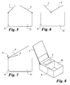
- the storage of the lids 1, 2 can, as shown in FIG. 5, independently of one another, be arranged on the end faces or, as shown in FIG. 6, in the middle. In both In individual cases, the covers only cover one of rooms 6 or 12.
- the lids 1, 2 can also be one above the other, with a coincident storage (Hinge) may be arranged, as shown in FIG. 7.
- the lid can do this forcibly opened only one after the other, but also independently, when the inner cover passes through a larger opening in the upper cover can, as shown in Fig. 8.
- the second cover 2 can only comprise a cover surface for the connection space, as shown in FIG. 8.
Landscapes
- Engineering & Computer Science (AREA)
- Power Engineering (AREA)
- Connection Or Junction Boxes (AREA)
- Connector Housings Or Holding Contact Members (AREA)
- Cartons (AREA)
- Coupling Device And Connection With Printed Circuit (AREA)
Applications Claiming Priority (2)
| Application Number | Priority Date | Filing Date | Title |
|---|---|---|---|
| DE10065088A DE10065088B4 (de) | 2000-12-23 | 2000-12-23 | Abgangs- oder Anschlußkasten |
| DE10065088 | 2000-12-23 |
Publications (3)
| Publication Number | Publication Date |
|---|---|
| EP1220406A2 true EP1220406A2 (fr) | 2002-07-03 |
| EP1220406A3 EP1220406A3 (fr) | 2002-10-16 |
| EP1220406B1 EP1220406B1 (fr) | 2005-12-21 |
Family
ID=7669039
Family Applications (1)
| Application Number | Title | Priority Date | Filing Date |
|---|---|---|---|
| EP01124200A Expired - Lifetime EP1220406B1 (fr) | 2000-12-23 | 2001-10-11 | Boítier de sortie ou d'interconnection |
Country Status (5)
| Country | Link |
|---|---|
| EP (1) | EP1220406B1 (fr) |
| AT (1) | ATE313868T1 (fr) |
| DE (2) | DE10065088B4 (fr) |
| DK (1) | DK1220406T3 (fr) |
| ES (1) | ES2255531T3 (fr) |
Cited By (4)
| Publication number | Priority date | Publication date | Assignee | Title |
|---|---|---|---|---|
| CN101783490A (zh) * | 2008-11-14 | 2010-07-21 | 华鹏集团有限公司 | 插接箱手动操作机构 |
| CN103579977A (zh) * | 2013-11-05 | 2014-02-12 | 江苏威腾母线有限公司 | 一种母线槽插接箱连锁机构 |
| CN107147022A (zh) * | 2017-05-12 | 2017-09-08 | 许继集团有限公司 | 一种二次设备装置 |
| CN115498570A (zh) * | 2021-06-18 | 2022-12-20 | 矢崎总业株式会社 | 电气接线箱 |
Families Citing this family (1)
| Publication number | Priority date | Publication date | Assignee | Title |
|---|---|---|---|---|
| DE102021103880A1 (de) | 2021-02-18 | 2022-08-18 | Metz Connect Tech Gmbh | Wandverteilergehäuse |
Family Cites Families (3)
| Publication number | Priority date | Publication date | Assignee | Title |
|---|---|---|---|---|
| US3335329A (en) * | 1965-07-02 | 1967-08-08 | Gen Electric | Fusible busway plug structure with movable plug carrier member |
| DE3437586A1 (de) * | 1984-10-13 | 1986-04-24 | Klöckner-Moeller Elektrizitäts GmbH, 5300 Bonn | Schienenverteiler |
| DE9201816U1 (de) * | 1992-02-13 | 1993-06-09 | Klöckner-Moeller GmbH, 5300 Bonn | Abgangskasten, insbesondere für Schienenverteiler |
-
2000
- 2000-12-23 DE DE10065088A patent/DE10065088B4/de not_active Expired - Fee Related
-
2001
- 2001-10-11 DK DK01124200T patent/DK1220406T3/da active
- 2001-10-11 ES ES01124200T patent/ES2255531T3/es not_active Expired - Lifetime
- 2001-10-11 DE DE50108451T patent/DE50108451D1/de not_active Expired - Lifetime
- 2001-10-11 AT AT01124200T patent/ATE313868T1/de not_active IP Right Cessation
- 2001-10-11 EP EP01124200A patent/EP1220406B1/fr not_active Expired - Lifetime
Cited By (6)
| Publication number | Priority date | Publication date | Assignee | Title |
|---|---|---|---|---|
| CN101783490A (zh) * | 2008-11-14 | 2010-07-21 | 华鹏集团有限公司 | 插接箱手动操作机构 |
| CN101783490B (zh) * | 2008-11-14 | 2013-09-18 | 江苏华鹏智能电气股份有限公司 | 插接箱手动操作机构 |
| CN103579977A (zh) * | 2013-11-05 | 2014-02-12 | 江苏威腾母线有限公司 | 一种母线槽插接箱连锁机构 |
| CN103579977B (zh) * | 2013-11-05 | 2016-10-05 | 江苏威腾母线有限公司 | 一种母线槽插接箱连锁机构 |
| CN107147022A (zh) * | 2017-05-12 | 2017-09-08 | 许继集团有限公司 | 一种二次设备装置 |
| CN115498570A (zh) * | 2021-06-18 | 2022-12-20 | 矢崎总业株式会社 | 电气接线箱 |
Also Published As
| Publication number | Publication date |
|---|---|
| ES2255531T3 (es) | 2006-07-01 |
| DE10065088B4 (de) | 2004-02-05 |
| EP1220406A3 (fr) | 2002-10-16 |
| DK1220406T3 (da) | 2006-05-08 |
| DE50108451D1 (de) | 2006-01-26 |
| EP1220406B1 (fr) | 2005-12-21 |
| DE10065088A1 (de) | 2002-07-18 |
| ATE313868T1 (de) | 2006-01-15 |
Similar Documents
| Publication | Publication Date | Title |
|---|---|---|
| DE10160090B4 (de) | Sicherungshalter | |
| DE102019212980A1 (de) | Elektrische Maschine mit einer Hochspannungsanschlussanordnung und einer Sicherheitssperreinrichtung | |
| DE102015104268A1 (de) | Elektrisches Schaltgerät mit elektrischen Klemmanschlüssen | |
| EP2154701B1 (fr) | Commutateur d'installation doté d'un dispositif de protection | |
| DE102017202135B4 (de) | Leistungsschalter | |
| EP1220406B1 (fr) | Boítier de sortie ou d'interconnection | |
| DE10115777A1 (de) | Mehrpoliges Schaltgerät für den Einsatz auf Sammelschienensystemen | |
| DE10131739B4 (de) | Stromwandler | |
| DE102015104873A1 (de) | Sperrsystem für einen Verschluss, der einen Stromschienenabschnitt von einem elektrischen Bauteilabschnitt einer elektrischen Einhausung trennt | |
| DE102010001411B4 (de) | Gehäuse für eine elektrische Schaltung | |
| EP0555665B1 (fr) | Coffret de sortie, notamment pour répartiteur de barres omnibus | |
| DE102020209257A1 (de) | Befestigungsvorrichtung und Reiheneinbaugerät | |
| EP1045414B1 (fr) | Disjoncteur-sectionneur à fusibles de haute puissance basse tension | |
| EP0857367B1 (fr) | Dispositif de separation de contacts d'une boite de derivation d'un systeme de distribution d'energie | |
| DE202008004009U1 (de) | Verteilergehäuse | |
| DE202019001525U1 (de) | Elektrischer Schalter | |
| DE2937671C2 (de) | Schlagwetter- oder explosionsgeschützte Anschlußvorrichtung | |
| EP0890971B1 (fr) | Couvercle pour contacts de fusibles dans les dispositifs à fusibles du type basse tension haute puissance | |
| EP1638123B1 (fr) | Disjoncteur avec prise de contact déplaçable | |
| EP2367192A1 (fr) | Dispositif de commutation destiné à la séparation de trois conducteurs électriques et d'un conducteur neutre | |
| EP1787358B1 (fr) | Module d'alimentation electrique comportant des bornes a ressort de rappel de cage | |
| EP0890970B1 (fr) | Couvercle pour contacts de fusibles dans les dispositifs à fusibles du type basse tension haute puissance | |
| DE4204238C2 (de) | Einschub mit einer schaltbaren NH-Sicherungsleiste für Einschubverteiler | |
| EP4384422B1 (fr) | Dispositif et procédé pour établir une connexion électrique entre un accumulateur d'énergie de traction électrique et un système électrique de véhicule à haute tension pour un véhicule à moteur | |
| EP0895663B1 (fr) | Boites de distribution, en particulier pour barre omnibus |
Legal Events
| Date | Code | Title | Description |
|---|---|---|---|
| PUAI | Public reference made under article 153(3) epc to a published international application that has entered the european phase |
Free format text: ORIGINAL CODE: 0009012 |
|
| AK | Designated contracting states |
Kind code of ref document: A2 Designated state(s): AT BE CH CY DE DK ES FI FR GB GR IE IT LI LU MC NL PT SE TR |
|
| AX | Request for extension of the european patent |
Free format text: AL;LT;LV;MK;RO;SI |
|
| PUAL | Search report despatched |
Free format text: ORIGINAL CODE: 0009013 |
|
| RIC1 | Information provided on ipc code assigned before grant |
Free format text: 7H 02G 5/08 A, 7H 02B 1/48 B |
|
| AK | Designated contracting states |
Kind code of ref document: A3 Designated state(s): AT BE CH CY DE DK ES FI FR GB GR IE IT LI LU MC NL PT SE TR |
|
| AX | Request for extension of the european patent |
Free format text: AL;LT;LV;MK;RO;SI |
|
| 17P | Request for examination filed |
Effective date: 20020905 |
|
| AKX | Designation fees paid |
Designated state(s): AT BE CH CY DE DK ES FI FR GB GR IE IT LI LU MC NL PT SE TR |
|
| 17Q | First examination report despatched |
Effective date: 20040706 |
|
| RAP1 | Party data changed (applicant data changed or rights of an application transferred) |
Owner name: SIEMENS AKTIENGESELLSCHAFT |
|
| GRAP | Despatch of communication of intention to grant a patent |
Free format text: ORIGINAL CODE: EPIDOSNIGR1 |
|
| GRAS | Grant fee paid |
Free format text: ORIGINAL CODE: EPIDOSNIGR3 |
|
| GRAA | (expected) grant |
Free format text: ORIGINAL CODE: 0009210 |
|
| AK | Designated contracting states |
Kind code of ref document: B1 Designated state(s): AT BE CH CY DE DK ES FI FR GB GR IE IT LI LU MC NL PT SE TR |
|
| PG25 | Lapsed in a contracting state [announced via postgrant information from national office to epo] |
Ref country code: IT Free format text: LAPSE BECAUSE OF FAILURE TO SUBMIT A TRANSLATION OF THE DESCRIPTION OR TO PAY THE FEE WITHIN THE PRESCRIBED TIME-LIMIT;WARNING: LAPSES OF ITALIAN PATENTS WITH EFFECTIVE DATE BEFORE 2007 MAY HAVE OCCURRED AT ANY TIME BEFORE 2007. THE CORRECT EFFECTIVE DATE MAY BE DIFFERENT FROM THE ONE RECORDED. Effective date: 20051221 Ref country code: IE Free format text: LAPSE BECAUSE OF FAILURE TO SUBMIT A TRANSLATION OF THE DESCRIPTION OR TO PAY THE FEE WITHIN THE PRESCRIBED TIME-LIMIT Effective date: 20051221 Ref country code: FI Free format text: LAPSE BECAUSE OF FAILURE TO SUBMIT A TRANSLATION OF THE DESCRIPTION OR TO PAY THE FEE WITHIN THE PRESCRIBED TIME-LIMIT Effective date: 20051221 |
|
| REG | Reference to a national code |
Ref country code: GB Ref legal event code: FG4D Free format text: NOT ENGLISH |
|
| REG | Reference to a national code |
Ref country code: CH Ref legal event code: EP |
|
| REG | Reference to a national code |
Ref country code: IE Ref legal event code: FG4D Free format text: LANGUAGE OF EP DOCUMENT: GERMAN |
|
| REF | Corresponds to: |
Ref document number: 50108451 Country of ref document: DE Date of ref document: 20060126 Kind code of ref document: P |
|
| REG | Reference to a national code |
Ref country code: CH Ref legal event code: NV Representative=s name: SIEMENS SCHWEIZ AG |
|
| PG25 | Lapsed in a contracting state [announced via postgrant information from national office to epo] |
Ref country code: GR Free format text: LAPSE BECAUSE OF FAILURE TO SUBMIT A TRANSLATION OF THE DESCRIPTION OR TO PAY THE FEE WITHIN THE PRESCRIBED TIME-LIMIT Effective date: 20060321 |
|
| REG | Reference to a national code |
Ref country code: SE Ref legal event code: TRGR |
|
| GBT | Gb: translation of ep patent filed (gb section 77(6)(a)/1977) |
Effective date: 20060328 |
|
| REG | Reference to a national code |
Ref country code: DK Ref legal event code: T3 |
|
| PG25 | Lapsed in a contracting state [announced via postgrant information from national office to epo] |
Ref country code: PT Free format text: LAPSE BECAUSE OF FAILURE TO SUBMIT A TRANSLATION OF THE DESCRIPTION OR TO PAY THE FEE WITHIN THE PRESCRIBED TIME-LIMIT Effective date: 20060522 |
|
| REG | Reference to a national code |
Ref country code: ES Ref legal event code: FG2A Ref document number: 2255531 Country of ref document: ES Kind code of ref document: T3 |
|
| REG | Reference to a national code |
Ref country code: IE Ref legal event code: FD4D |
|
| ET | Fr: translation filed | ||
| PLBE | No opposition filed within time limit |
Free format text: ORIGINAL CODE: 0009261 |
|
| STAA | Information on the status of an ep patent application or granted ep patent |
Free format text: STATUS: NO OPPOSITION FILED WITHIN TIME LIMIT |
|
| PG25 | Lapsed in a contracting state [announced via postgrant information from national office to epo] |
Ref country code: MC Free format text: LAPSE BECAUSE OF NON-PAYMENT OF DUE FEES Effective date: 20061031 |
|
| 26N | No opposition filed |
Effective date: 20060922 |
|
| PG25 | Lapsed in a contracting state [announced via postgrant information from national office to epo] |
Ref country code: CY Free format text: LAPSE BECAUSE OF FAILURE TO SUBMIT A TRANSLATION OF THE DESCRIPTION OR TO PAY THE FEE WITHIN THE PRESCRIBED TIME-LIMIT Effective date: 20051221 |
|
| PGFP | Annual fee paid to national office [announced via postgrant information from national office to epo] |
Ref country code: NL Payment date: 20081017 Year of fee payment: 8 |
|
| PGFP | Annual fee paid to national office [announced via postgrant information from national office to epo] |
Ref country code: DK Payment date: 20081016 Year of fee payment: 8 Ref country code: LU Payment date: 20081021 Year of fee payment: 8 |
|
| PGFP | Annual fee paid to national office [announced via postgrant information from national office to epo] |
Ref country code: AT Payment date: 20080910 Year of fee payment: 8 Ref country code: ES Payment date: 20081112 Year of fee payment: 8 |
|
| PGFP | Annual fee paid to national office [announced via postgrant information from national office to epo] |
Ref country code: BE Payment date: 20081030 Year of fee payment: 8 Ref country code: SE Payment date: 20081016 Year of fee payment: 8 |
|
| REG | Reference to a national code |
Ref country code: CH Ref legal event code: PCAR Free format text: SIEMENS SCHWEIZ AG;INTELLECTUAL PROPERTY FREILAGERSTRASSE 40;8047 ZUERICH (CH) |
|
| PGFP | Annual fee paid to national office [announced via postgrant information from national office to epo] |
Ref country code: CH Payment date: 20090114 Year of fee payment: 8 |
|
| BERE | Be: lapsed |
Owner name: *SIEMENS A.G. Effective date: 20091031 |
|
| REG | Reference to a national code |
Ref country code: NL Ref legal event code: V1 Effective date: 20100501 |
|
| REG | Reference to a national code |
Ref country code: CH Ref legal event code: PL |
|
| EUG | Se: european patent has lapsed | ||
| REG | Reference to a national code |
Ref country code: DK Ref legal event code: EBP |
|
| PG25 | Lapsed in a contracting state [announced via postgrant information from national office to epo] |
Ref country code: NL Free format text: LAPSE BECAUSE OF NON-PAYMENT OF DUE FEES Effective date: 20100501 |
|
| PG25 | Lapsed in a contracting state [announced via postgrant information from national office to epo] |
Ref country code: AT Free format text: LAPSE BECAUSE OF NON-PAYMENT OF DUE FEES Effective date: 20091011 |
|
| PG25 | Lapsed in a contracting state [announced via postgrant information from national office to epo] |
Ref country code: CH Free format text: LAPSE BECAUSE OF NON-PAYMENT OF DUE FEES Effective date: 20091031 Ref country code: BE Free format text: LAPSE BECAUSE OF NON-PAYMENT OF DUE FEES Effective date: 20091031 Ref country code: LI Free format text: LAPSE BECAUSE OF NON-PAYMENT OF DUE FEES Effective date: 20091031 |
|
| PG25 | Lapsed in a contracting state [announced via postgrant information from national office to epo] |
Ref country code: DK Free format text: LAPSE BECAUSE OF NON-PAYMENT OF DUE FEES Effective date: 20091031 |
|
| REG | Reference to a national code |
Ref country code: ES Ref legal event code: FD2A Effective date: 20110401 |
|
| PG25 | Lapsed in a contracting state [announced via postgrant information from national office to epo] |
Ref country code: LU Free format text: LAPSE BECAUSE OF NON-PAYMENT OF DUE FEES Effective date: 20091011 |
|
| PG25 | Lapsed in a contracting state [announced via postgrant information from national office to epo] |
Ref country code: SE Free format text: LAPSE BECAUSE OF NON-PAYMENT OF DUE FEES Effective date: 20091012 |
|
| PG25 | Lapsed in a contracting state [announced via postgrant information from national office to epo] |
Ref country code: ES Free format text: LAPSE BECAUSE OF NON-PAYMENT OF DUE FEES Effective date: 20110322 |
|
| PG25 | Lapsed in a contracting state [announced via postgrant information from national office to epo] |
Ref country code: ES Free format text: LAPSE BECAUSE OF NON-PAYMENT OF DUE FEES Effective date: 20091012 |
|
| PGFP | Annual fee paid to national office [announced via postgrant information from national office to epo] |
Ref country code: GB Payment date: 20141013 Year of fee payment: 14 Ref country code: FR Payment date: 20141017 Year of fee payment: 14 |
|
| PGFP | Annual fee paid to national office [announced via postgrant information from national office to epo] |
Ref country code: IT Payment date: 20141029 Year of fee payment: 14 |
|
| PGFP | Annual fee paid to national office [announced via postgrant information from national office to epo] |
Ref country code: DE Payment date: 20141219 Year of fee payment: 14 |
|
| PGFP | Annual fee paid to national office [announced via postgrant information from national office to epo] |
Ref country code: TR Payment date: 20131011 Year of fee payment: 13 |
|
| REG | Reference to a national code |
Ref country code: DE Ref legal event code: R119 Ref document number: 50108451 Country of ref document: DE |
|
| GBPC | Gb: european patent ceased through non-payment of renewal fee |
Effective date: 20151011 |
|
| PG25 | Lapsed in a contracting state [announced via postgrant information from national office to epo] |
Ref country code: DE Free format text: LAPSE BECAUSE OF NON-PAYMENT OF DUE FEES Effective date: 20160503 Ref country code: GB Free format text: LAPSE BECAUSE OF NON-PAYMENT OF DUE FEES Effective date: 20151011 Ref country code: IT Free format text: LAPSE BECAUSE OF NON-PAYMENT OF DUE FEES Effective date: 20151011 |
|
| REG | Reference to a national code |
Ref country code: FR Ref legal event code: ST Effective date: 20160630 |
|
| PG25 | Lapsed in a contracting state [announced via postgrant information from national office to epo] |
Ref country code: FR Free format text: LAPSE BECAUSE OF NON-PAYMENT OF DUE FEES Effective date: 20151102 |
|
| PG25 | Lapsed in a contracting state [announced via postgrant information from national office to epo] |
Ref country code: TR Free format text: LAPSE BECAUSE OF NON-PAYMENT OF DUE FEES Effective date: 20151011 |