EP1220760B1 - Verschlussvorrichtung und verfahren zum verschliessen der öffnung eines behälters - Google Patents
Verschlussvorrichtung und verfahren zum verschliessen der öffnung eines behälters Download PDFInfo
- Publication number
- EP1220760B1 EP1220760B1 EP00962435A EP00962435A EP1220760B1 EP 1220760 B1 EP1220760 B1 EP 1220760B1 EP 00962435 A EP00962435 A EP 00962435A EP 00962435 A EP00962435 A EP 00962435A EP 1220760 B1 EP1220760 B1 EP 1220760B1
- Authority
- EP
- European Patent Office
- Prior art keywords
- tank
- plate
- wall
- opening
- layer
- Prior art date
- Legal status (The legal status is an assumption and is not a legal conclusion. Google has not performed a legal analysis and makes no representation as to the accuracy of the status listed.)
- Expired - Lifetime
Links
Images



Classifications
-
- B—PERFORMING OPERATIONS; TRANSPORTING
- B60—VEHICLES IN GENERAL
- B60K—ARRANGEMENT OR MOUNTING OF PROPULSION UNITS OR OF TRANSMISSIONS IN VEHICLES; ARRANGEMENT OR MOUNTING OF PLURAL DIVERSE PRIME-MOVERS IN VEHICLES; AUXILIARY DRIVES FOR VEHICLES; INSTRUMENTATION OR DASHBOARDS FOR VEHICLES; ARRANGEMENTS IN CONNECTION WITH COOLING, AIR INTAKE, GAS EXHAUST OR FUEL SUPPLY OF PROPULSION UNITS IN VEHICLES
- B60K15/00—Arrangement in connection with fuel supply of combustion engines or other fuel consuming energy converters, e.g. fuel cells; Mounting or construction of fuel tanks
- B60K15/03—Fuel tanks
- B60K15/035—Fuel tanks characterised by venting means
- B60K15/03519—Valve arrangements in the vent line
-
- B—PERFORMING OPERATIONS; TRANSPORTING
- B60—VEHICLES IN GENERAL
- B60K—ARRANGEMENT OR MOUNTING OF PROPULSION UNITS OR OF TRANSMISSIONS IN VEHICLES; ARRANGEMENT OR MOUNTING OF PLURAL DIVERSE PRIME-MOVERS IN VEHICLES; AUXILIARY DRIVES FOR VEHICLES; INSTRUMENTATION OR DASHBOARDS FOR VEHICLES; ARRANGEMENTS IN CONNECTION WITH COOLING, AIR INTAKE, GAS EXHAUST OR FUEL SUPPLY OF PROPULSION UNITS IN VEHICLES
- B60K15/00—Arrangement in connection with fuel supply of combustion engines or other fuel consuming energy converters, e.g. fuel cells; Mounting or construction of fuel tanks
- B60K15/03—Fuel tanks
- B60K15/03177—Fuel tanks made of non-metallic material, e.g. plastics, or of a combination of non-metallic and metallic material
-
- F—MECHANICAL ENGINEERING; LIGHTING; HEATING; WEAPONS; BLASTING
- F16—ENGINEERING ELEMENTS AND UNITS; GENERAL MEASURES FOR PRODUCING AND MAINTAINING EFFECTIVE FUNCTIONING OF MACHINES OR INSTALLATIONS; THERMAL INSULATION IN GENERAL
- F16K—VALVES; TAPS; COCKS; ACTUATING-FLOATS; DEVICES FOR VENTING OR AERATING
- F16K24/00—Devices, e.g. valves, for venting or aerating enclosures
- F16K24/04—Devices, e.g. valves, for venting or aerating enclosures for venting only
- F16K24/042—Devices, e.g. valves, for venting or aerating enclosures for venting only actuated by a float
- F16K24/044—Devices, e.g. valves, for venting or aerating enclosures for venting only actuated by a float the float being rigidly connected to the valve element, the assembly of float and valve element following a substantially translational movement when actuated, e.g. also for actuating a pilot valve
-
- Y—GENERAL TAGGING OF NEW TECHNOLOGICAL DEVELOPMENTS; GENERAL TAGGING OF CROSS-SECTIONAL TECHNOLOGIES SPANNING OVER SEVERAL SECTIONS OF THE IPC; TECHNICAL SUBJECTS COVERED BY FORMER USPC CROSS-REFERENCE ART COLLECTIONS [XRACs] AND DIGESTS
- Y10—TECHNICAL SUBJECTS COVERED BY FORMER USPC
- Y10T—TECHNICAL SUBJECTS COVERED BY FORMER US CLASSIFICATION
- Y10T137/00—Fluid handling
- Y10T137/0753—Control by change of position or inertia of system
- Y10T137/0874—Vent opening or closing on tipping container
-
- Y—GENERAL TAGGING OF NEW TECHNOLOGICAL DEVELOPMENTS; GENERAL TAGGING OF CROSS-SECTIONAL TECHNOLOGIES SPANNING OVER SEVERAL SECTIONS OF THE IPC; TECHNICAL SUBJECTS COVERED BY FORMER USPC CROSS-REFERENCE ART COLLECTIONS [XRACs] AND DIGESTS
- Y10—TECHNICAL SUBJECTS COVERED BY FORMER USPC
- Y10T—TECHNICAL SUBJECTS COVERED BY FORMER US CLASSIFICATION
- Y10T137/00—Fluid handling
- Y10T137/2931—Diverse fluid containing pressure systems
- Y10T137/3003—Fluid separating traps or vents
- Y10T137/3084—Discriminating outlet for gas
- Y10T137/309—Fluid sensing valve
- Y10T137/3099—Float responsive
-
- Y—GENERAL TAGGING OF NEW TECHNOLOGICAL DEVELOPMENTS; GENERAL TAGGING OF CROSS-SECTIONAL TECHNOLOGIES SPANNING OVER SEVERAL SECTIONS OF THE IPC; TECHNICAL SUBJECTS COVERED BY FORMER USPC CROSS-REFERENCE ART COLLECTIONS [XRACs] AND DIGESTS
- Y10—TECHNICAL SUBJECTS COVERED BY FORMER USPC
- Y10T—TECHNICAL SUBJECTS COVERED BY FORMER US CLASSIFICATION
- Y10T137/00—Fluid handling
- Y10T137/8593—Systems
- Y10T137/86292—System with plural openings, one a gas vent or access opening
- Y10T137/86324—Tank with gas vent and inlet or outlet
Definitions
- the present invention relates to a shutter system of an opening of a tank.
- Liquid and gas tanks in use in industry or on board in vehicles of diverse nature must generally meet standards leakage and permeability in relation to the type of use for which they are designed and the environmental requirements they must meet.
- the design of liquid tanks and gas evolves accordingly rapidly to techniques capable of better to guarantee watertightness and safety under various conditions of use.
- efforts have also been made to minimize losses Origin pipelines and various accessories related to tanks.
- a way sometimes used was to incorporate some accessories and piping inside reservoirs, thus eliminating their interface with the outside atmosphere.
- multilayer structures were used including one or more layers of impermeable material. incorporation accessories in such tanks poses the problem of sealing and impervious of the opening made in these tanks, in order to be able to insert the accessories. In addition, emissions from accessories take on a much greater relative importance with respect to reservoirs multilayer materials whose intrinsic permeability is significantly lower than the classic tanks.
- the present invention aims to provide a closure system of a simpler tank that is suitable for tanks of multilayer structure and limit of significantly the loss of liquid and gas compared to the systems conventional shutter.
- the invention relates to a shutter system of an opening of a plastic tank of multilayer structure, consisting of a plastic plate welded to the tank wall at the location of the around the opening, according to which the plate itself consists of a multilayer structure whose outer layer welded to the tank has a composition compatible with that of the layer constituting the outer wall of the tank.
- outer layer is meant a layer with one of the faces is adjacent to another layer of the structure and whose other face is in contact with the external environment to this structure.
- reservoir is meant a closed enclosure, of various shapes, generally watertight to the outside, which can be equipped with various internal accessories or through the wall of the enclosure.
- the tank can be a gas tank, a liquid tank or a tank intended to contain both a gas and a liquid.
- it is a liquid reservoir or a reservoir for liquid also containing a gaseous phase.
- Some tanks have one or more openings, i.e. a cutout of circular shape or not, made through the wall of the tank for various reasons, for example, in order to be able to introduce into the tank one or more accessories which it is not possible to incorporate during its manufacturing.
- the shutter system is designed for tanks in plastic material of multilayer structure.
- plastic we mean all polymeric synthetic material, thermoplastic or thermosetting solid state under ambient conditions and mixtures at least two of these materials.
- the targeted polymers include both homopolymers than copolymers (especially binary or ternary). of the Examples of such copolymers are, in a nonlimiting manner: copolymers with random distribution ("statistical" copolymers), block copolymers, block copolymers and graft copolymers. Polymers thermoplastics, including thermoplastic elastomers are preferred.
- the plastic tanks according to the invention are in the form of form of multilayer structure tanks.
- the tanks comprising at less a layer of high density polyethylene are particularly preferred.
- Particularly preferred reservoirs are those whose structure comprises in in addition to at least one inner layer of barrier material, i.e. a material, generally of polymeric nature which has a very high impermeability to certain liquids and gases.
- barrier compositions such as those used to waterproof fuel tanks.
- barrier compositions are, without limitation: resins based on polyamides or copolyamides, statistical copolymers ethylene and vinyl alcohol, or liquid crystal polymers thermotropic substances such as the copolyesters of p-hydroxybenzoic acid and either 6-hydroxy-2-naphthoic acid, either terephthalic acid and 4,4'-biphenol (eg copolyesters marketed under the brand names VECTRA® and XYDAR®).
- the material constituting the plate comprises a plastic material.
- the plate forming part of the shutter system according to the invention is made exclusively of plastic.
- the plaque may have various forms; most often, the shape of the plate depends various types of tank and the location of the opening to be plugged on the surface of these tanks.
- the plate often has a flat surface or slightly curved, especially in the case of a small opening dimensions such as, for example, circular diameter openings not exceeding 80 mm.
- the plate is according to the invention, welded to the tank wall at the location around the opening. This means that the plate is secured with this wall by contacting and partially interpenetrating the molecules of a portion of the surface of one of the two main faces of the plate adjacent to the ends thereof and forming a ring-shaped joining surface closed, circular or of any shape and marrying more or less faithfully the outer perimeter of this face of the plate with the molecules of a surface tank, located on the edge of the opening, on the whole of its periphery.
- the plate itself consists of a structure multilayer whose outer layer welded to the reservoir has a composition compatible with that of the layer constituting the outer wall of the tank.
- Compatibility means here a chemical and physical compatibility constituents of the respective compositions of the layer of the welded plate on the tank and the outer wall thereof in the vicinity of the opening.
- a good compatibility avoids the segregation phenomena of some of the constituents of the respective compositions of the welded parts, as well as any chemical reaction and physical phenomenon detrimental to the properties of the reservoir whose opening is thus closed.
- Good compatibility guarantees in general long-term adhesion of the plate on the tank.
- a particular preferred system according to the invention is that where the tank and plate include liquid waterproofing means and gases.
- the means of waterproofing the plate and the tank can be identical or different. It is generally preferred that these means are identical, in particular that they comprise barrier compositions identical.
- barrier compositions can be incorporated into one of the layers of the plate or insert an additional layer inside the structure particular consisting essentially of barrier composition.
- an additional layer is inserted inside the structure essentially a barrier composition.
- the multilayer structure of the plate may be different from that of walls of the tank itself. It can also be identical to this one. We prefer often shutter systems in which the structure of the plate is identical to that of the walls of the tank. Especially preferred are the systems in which, within identical structures, the compositions barrier are themselves identical and constitute polymeric layers identical.
- the multilayer structure of the plate may also comprise two distinct barrier layers.
- a preferred example according to this variant is that of the plates comprising two complete structures identical to that of the walls of the reservoir, stacked one on the other and resulting from the compression of two structures identical to the walls of the reservoir.
- Another variant consists in producing, in the vicinity of the edge of the plate, a projection in which the thicknesses of the layers are reduced, in particular those of the layers other than the barrier layer. The interest here is to further limit the risk of emission loss at the weld site of the plate on the tank.
- the system according to the invention is well suited for sealing a simple opening a tank. It is also suitable for closing an opening overcoming an accessory located in the tank.
- the plate is secured to at least one accessory located on the side inside the tank.
- Accessory means any organ in general through which liquid or gas passes, or is in contact with liquid or gas and which fulfills a particular function specific to the device of which the tank, including a liquid and / or gas transport function between two other organs.
- Any combination of at least two accessories may be used, possibly in the presence of several copies of the same accessory.
- the accessory is integral with the plate, that is, it is bonded to the plate by mechanical means.
- the accessory is fixed to the plate by any mechanical means compatible with the type of tank, the the nature of the liquid and gas stored in it and the usual use that is made of tank.
- the plate can provide a means of gripping and transporting the accessory.
- a plate on which the accessory by a mechanical fixing device are, by example of screws, nuts, clipping system, ....
- the integral accessory of the plate is in relation to it on the plate face which is inside the tank, when the shutter is made.
- ROV valves R oll- O ver- V alve
- ORVR O n board R efueling V for R ecovery
- flaps or vapor recovery device when filling the tank OBD devices ( "O n B oard dIAGNOSIS”) or on-board diagnostic devices, liquid-vapor separators.
- Some of these accessories may include at least one conduit through the plate through a hole pierced therein. It is in this case often advantageous to provide the outlet port of the conduit with a seal.
- the plate may also have been shaped to be adapted to the best to the environment of the opening to be closed as well as to the shape and the clutter of the accessory which it is solidary.
- a plate integral with a liquid-vapor separator comprising a vapor vent pipe that passes through the plate through an orifice has given good results.
- a particular sealing system consists in using a reservoir whose wall carries fastening lugs in the vicinity of the opening. These allow to support the wall during the welding operation, in case of flexible deformation of this wall.
- the invention also relates to a method for sealing a tank plastic material of multilayer structure which allows to strongly limit the losses of liquid and gas in the environment. It allows, as an option, the integration of at least one accessory inside the tank.
- the invention relates to a method of closing an opening of a plastic tank of multilayer structure by a plate made of plastic material according to which the plate is welded to the outer layer of the tank around the perimeter of the opening which is characterized in that one welded a multilayer structure plate whose layer welded to the reservoir has a composition compatible with the composition of the outer layer of tank.
- the plate used in this process may be of various origin. She can, for example, having been manufactured independently of the tank itself, at a different moment or not, by means of a clean process which is not necessarily identical to that used to manufacture the reservoir.
- the plate can be obtained by coextrusion followed by molding by compression. It may also have been obtained by molding according to one of many known techniques. Such techniques are, for example, the blow molding, compression molding, injection molding and thermoforming.
- the plate may have been manufactured simultaneously with the reservoir and cut into the plastic material of multilayer structure used for make the tank. This way of proceeding is particularly advantageous from the point of view of synchronizing the production of tanks equipped with their accessories. It is for example possible to cut the plate directly in a region of the tank wall, after completion of the latter or of a part of it. This variant also assumes that the outermost layer the multilayer structure of the tank is compatible with its outermost layer.
- Another variant is to cut the plate into the waste of manufacture of the tank, provided they have the multilayer structure adequate.
- the operation of welding the plate on the tank can be done by any technique generally known by itself. We can, for example, use the mirror welding technique or the laser welding technique. The mirror welding technique is preferred.
- solidarise at least one accessory to the plate, on the inside of the tank. All compatible with the tank, the nature of the liquid and gas and its conditions of use can generally be suit.
- a first variant consists in welding at least one accessory to the plate before shutting off the tank opening by welding the the plate integral with the accessory on the periphery of this opening.
- the plate plays the role of supporting the accessory and allows its introduction easily inside the tank.
- a second variant consists, on the contrary, in first step, at least one accessory on the inner wall of the adjacent reservoir at the opening and, in a second subsequent step, to close the tank by simultaneous welding of the plate on the accessory and on the periphery of the opening.
- the invention also relates to a sealing method which remedies these problems of flexible deformation of the tank wall by supporting the wall of the reservoir in the vicinity of the opening during the welding operation of the plate by means of lugs molded on this wall
- the lugs were molded on the outer wall of the tank in the vicinity around the opening.
- the tank wall is supported here at means of clamps that grip the lugs.
- Pins similar to those described above can also be used when the plate is cut in the wall of the tank, so as to avoid deformations of it.
- the pins can still be used to correct, before the operation of welding, a flatness defect that would occur on the surface of the tank.
- the invention also relates to the use of the method described above for close an opening of a fuel tank, in particular for a vehicle automobile.
- Motor vehicle means motor-driven vehicles thermal such as trucks, cars and motorcycles.
- FIG. 1 represents a sectional view of a fuel tank (4) at 6 layers (HDPE / Regrinded / PE grafted maleic anhydride / EVOH / PE grafted maleic anhydride / HDPE) having an opening closed by a plate (1) wearing two accessories.
- the coextruded plate (1) has been compression molded from the tank blow mold by clamping two walls of the tank and was welded by the technique of the heating mirror on a pipette (2) in HDPE.
- the pipette (2) also mechanically snaps a valve ROV (5) provided with a skirt (3) of polyacetal.
- the tip of the pipette (2) has been connected to an internal ventilation line in the tank (4), not shown on the Fig.
- the plate (1) was then welded using a heating mirror on the wall external tank (4).
- FIG. 2 illustrates a system similar to that of FIG. a pipette (2), a ROV valve (5) and the wall of a tank (4) have been welded simultaneously with a compression molded coextruded plate (1).
- This plate (1) was obtained by prior blowing into a cavity annexed to that serving for blowing the tank.
- the valve (5) has always been fixed to the pipette (2) by snapping, but the pipette-valve assembly has been deposited on a flange (8) cut into a boss of the tank wall (4) on the around an opening.
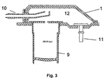
- FIG. 3 illustrates a coextruded plate (1) closing an opening of a tank and carrying a liquid-vapor separator.
- the plate (1) has been molded, as in the case described in FIG. 2, by blowing a parison into a auxiliary cavity to that used for blowing the tank.
- the plate (1) has been equipped and traversed by a degassing pipette (10) which has an orifice raised internal plate attached to the plate and provided with a seal at the crossing point of the plate (1).
- This pipette was made of low permeability material.
- a valve (9) of type ORVR was welded on the wall of the tank along around the opening and communicated directly with the internal volume of it.
- a pipette (11) was also welded to the reservoir and connected to the inside of it to a flap (not shown in the figure) located in another tank area.
- Figure 4 illustrates a restraint system for deformation zones flexible tank near the opening on the tank wall according to diametrical positions close to the opening.
- Clamps (14) were then brought into open position over the tank wall so as to surround each group of 3 pins (13). After blocking their position in the direction perpendicular to the wall of the tank, they have been closed and tightened on the lugs, so as to support the wall of the tank during the entire duration of drilling operations of the opening, possible machining of its edges, possible introduction of accessories and welding the plate to close the tank.
Landscapes
- Engineering & Computer Science (AREA)
- Mechanical Engineering (AREA)
- General Engineering & Computer Science (AREA)
- Sustainable Energy (AREA)
- Chemical & Material Sciences (AREA)
- Combustion & Propulsion (AREA)
- Transportation (AREA)
- Sustainable Development (AREA)
- Life Sciences & Earth Sciences (AREA)
- Cooling, Air Intake And Gas Exhaust, And Fuel Tank Arrangements In Propulsion Units (AREA)
- Closures For Containers (AREA)
- Lining Or Joining Of Plastics Or The Like (AREA)
- Electrical Discharge Machining, Electrochemical Machining, And Combined Machining (AREA)
- Refuse Collection And Transfer (AREA)
- Closing Of Containers (AREA)
- Supplying Of Containers To The Packaging Station (AREA)
- Transmission Of Braking Force In Braking Systems (AREA)
Claims (15)
- System zum Verschließen der Öffnung eines Behälters (4) aus Kunststoff mit mehrlagigem Aufbau, der zumindest eine Polyethylenschicht hoher Dichte und zumindest eine Innenschicht aus einem Trennmaterial aufweist, mit einer Platte (1) aus Kunststoff, die an ihrem Umfang an der Außenschicht des Behälters (4) um den Umfang der Öffnung herum angreift, wobei diese Platte (1), die ebenfalls zumindest eine Schicht aus Polyethylen hoher Dichte und zumindest eine Innenschicht aus einem Trennmaterial aufweist, mit der Wand des Behälters (4) im Bereich des Umfanges der Öffnung verschweißt ist und ihrerseits einen mehrlagigen Aufbau hat, dessen Außenschicht, die mit dem Behälter (4) verschweißt ist, eine Zusammensetzung aufweist, die mit jener der die Außenwand des Behälters (4) bildenden Schicht kompatibel ist,
dadurch gekennzeichnet, daß
an der Stelle, an welcher eine Außenschicht der Platte (1) auf die Schicht geschweißt ist, welche die Außenwand des Behälters (4) bildet, die Platte (1) und die Wand des Behälters (4) derart überlagert sind, daß die Anzahl der einander an dieser Stelle überlagernden Schichten gleich der Summe der Anzahl der Schichten in der Platte (1) und der Anzahl der Schichten in der Wand des Behälters (4) ist, und derart, daß die Trennschicht der Platte (1) nicht in Kontinuität mit der Trennschicht der Wand des Behälters (4) ist. - System nach dem vorhergehenden Anspruch, dadurch gekennzeichnet, daß die Platte (1) die Wand des Behälters (4) nicht durchsetzt.
- System nach Anspruch 1 oder 2, dadurch gekennzeichnet, daß der Behälter (4) und die Platte (1) identische Mittel zum Undurchlässigmachen gegen Flüssigkeiten und Gase aufweisen und aus dem gleichen mehrlagigen Aufbau gebildet sind.
- System nach einem der vorhergehenden Ansprüche, dadurch gekennzeichnet, daß die Platte (1) mit einer Leitung (10) ausgestattet und von dieser durchsetzt ist.
- System nach dem vorhergehenden Anspruch, dadurch gekennzeichnet, daß die Leitung (10) an ihrem Durchgang durch die Platte (1) mit einer Dichtung versehen ist.
- System nach einem der Ansprüche 1 bis 5, dadurch gekennzeichnet, daß die Platte (1) mit zumindest einem Zubehör (2) fest verbunden ist, das auf der Innenseite des Behälters angeordnet ist.
- System nach dem vorhergehenden Anspruch, dadurch gekennzeichnet, daß das Zubehör (2) eine Flüssigkeits-Dampf-Trenneinrichtung ist, die eine Austragleitung für Dämpfe (10) aufweist, welche die Platte (1) durch eine Öffnung durchsetzt.
- System nach einem der Ansprüche 1 bis 7, dadurch gekennzeichnet, daß die Platte (1) einen mehrlagigen Aufbau hat, mit zwei vollständig identischen Strukturen, wie jene der Wände des Behälters (4), wobei die Strukturen übereinandergelegt sind und aus dem Anpressen der beiden identischen Strukturen an die Wände des Behälters (4) gebildet ist.
- System nach einem der vorhergehenden Ansprüche, dadurch gekennzeichnet, daß die Wand des Behälters (4) Befestigungsansätze (13) in der Nähe der Öffnung aufweist.
- Verfahren zum Verschließen einer Öffnung eines Behälters (4) aus Kunststoff mit mehrlagigem Aufbau mit zumindest einer Polyethylenschicht hoher Dichte und zumindest einer Innenschicht aus einem Trennmaterial, durch eine Platte (1) aus Kunststoff, die an ihrem Umfang an der Außenschicht des Behälters (4) angreift, welche die Öffnung umgibt, wobei die Platte (1) ebenfalls zumindest eine Polyethylenschicht hoher Dichte und zumindest eine Innenschicht aus einem Trennmaterial aufweist, wobei die Platte (1) an die Wand des Behälters (4) im Bereich des Umfanges der Öffnung angeschweißt wird, wobei die Platte (1) ihrerseits einen mehrlagigen Aufbau hat, dessen Außenschicht, die an den Behälter (4) geschweißt ist, eine Zusammensetzung hat, die mit jener der die Außenwand des Behälters (4) bildenden Schicht kompatibel ist,
dadurch gekennzeichnet, daß
man die Platte (1) derart anschweißt, daß in dem Bereich, in welchem die Außenschicht der Platte an die Schicht angeschweißt ist, welche die Außenwand des Behälters (4) bildet, die Platte (1) und die Wand des Behälters (4) derart überlagert sind, daß die Anzahl der überlagerten Schichten an dieser Stelle gleich der Summe der Anzahl der Schichten in der Platte (4) und der Anzahl der Schichten in der Wand des Behälters (4) ist, und derart, daß die Trennschicht der Platte (1) nicht in Kontinuität mit der Trennschicht der Wand des Behälters (4) ist. - Verfahren nach dem vorhergehenden Anspruch, dadurch gekennzeichnet, daß man durch Schweißen zumindest ein Zubehör (2) mit der Platte (1) an der Innenseite des Behälters (4) verbindet.
- Verfahren nach Anspruch 11, dadurch gekennzeichnet, daß man zumindest ein Zubehör (2) an die Platte (1) anschweißt, vor dem Verschließen der Öffnung des Behälters (4) durch Anschweißen der das Zubehör (2) tragenden Platte (1) an den Umfang dieser Öffnung.
- Verfahren nach Anspruch 11, dadurch gekennzeichnet, daß man vor dem Verschließen des Behälters (4) zumindest ein Zubehör (2) an der Innenwand des Behälters (4) nahe der Öffnung durch gleichzeitiges Anschweißen der Platte (1) an das Zubehör (2) und an den Umfang der Öffnung befestigt.
- Verfahren nach einem der Ansprüche 10 bis 13, dadurch gekennzeichnet, daß man die Wand des Behälters (4) in der Nähe der Öffnung während des Anschweißens der Platte (1) mit Hilfe von Ansätzen (13) abstützt, die an dieser Wand angeformt sind.
- Verfahren nach einem der Ansprüche 10 bis 14, dadurch gekennzeichnet, daß der Behälter ein Kraftstoffbehälter (4) für ein Automobilfahrzeug ist.
Applications Claiming Priority (3)
| Application Number | Priority Date | Filing Date | Title |
|---|---|---|---|
| BE9900632 | 1999-09-22 | ||
| BE9900632A BE1012907A3 (fr) | 1999-09-22 | 1999-09-22 | Systeme et procede d'obturation d'une ouverture d'un reservoir. |
| PCT/EP2000/008613 WO2001021428A1 (fr) | 1999-09-22 | 2000-09-04 | Systeme et procede d'obturation d'une ouverture d'un reservoir |
Publications (2)
| Publication Number | Publication Date |
|---|---|
| EP1220760A1 EP1220760A1 (de) | 2002-07-10 |
| EP1220760B1 true EP1220760B1 (de) | 2004-12-01 |
Family
ID=3892098
Family Applications (1)
| Application Number | Title | Priority Date | Filing Date |
|---|---|---|---|
| EP00962435A Expired - Lifetime EP1220760B1 (de) | 1999-09-22 | 2000-09-04 | Verschlussvorrichtung und verfahren zum verschliessen der öffnung eines behälters |
Country Status (9)
| Country | Link |
|---|---|
| US (1) | US6843267B1 (de) |
| EP (1) | EP1220760B1 (de) |
| JP (1) | JP4527334B2 (de) |
| AT (1) | ATE283773T1 (de) |
| AU (1) | AU7416600A (de) |
| BE (1) | BE1012907A3 (de) |
| BR (1) | BR0014208A (de) |
| DE (1) | DE60016438T2 (de) |
| WO (1) | WO2001021428A1 (de) |
Families Citing this family (17)
| Publication number | Priority date | Publication date | Assignee | Title |
|---|---|---|---|---|
| US6901384B2 (en) * | 2000-06-03 | 2005-05-31 | American Home Credit, Inc. | System and method for automated process of deal structuring |
| US6915812B2 (en) | 2000-09-12 | 2005-07-12 | Alfmeier Corporation | Low permeation weldable fuel tank assembly |
| FR2831112B1 (fr) * | 2001-10-24 | 2004-01-23 | Inergy Automotive Systems Man | Reservoir a carburant et procede de fabrication de ce reservoir |
| FR2831113B1 (fr) * | 2001-10-24 | 2004-01-02 | Inergy Automotive Systems Man | Systeme et procede d'obturation d'une ouverture d'un reservoir |
| US7704440B2 (en) * | 2003-12-02 | 2010-04-27 | Ti Group Automotive Systems, L.L.C. | Fuel system component and method of manufacture |
| US7565986B2 (en) * | 2003-12-02 | 2009-07-28 | Ti Group Automotive Systems, L.L.C. | Fuel system component and method of manufacture |
| US8381928B2 (en) | 2004-06-04 | 2013-02-26 | Ti Group Automotive Systems, L.L.C. | Multilayer fuel tank with a seam having an overlay for reducing vapor permeation |
| WO2007090830A1 (en) * | 2006-02-07 | 2007-08-16 | Inergy Automotive Systems Research (Société Anonyme) | Process for manufacturing a fuel tank |
| FR2897017B1 (fr) * | 2006-02-07 | 2009-01-23 | Inergy Automotive Systems Res | Procede de fabrication d'un reservoir a carburant |
| US20070261752A1 (en) * | 2006-04-13 | 2007-11-15 | Stant Manufacturing Inc. | Multiple-layer fluid fuel apparatus |
| FR2906503A1 (fr) | 2006-09-28 | 2008-04-04 | Inergy Automotive Systems Res | Dispositif de fixation d'un film sur un reservoir en matiere plastique |
| WO2008113821A1 (de) * | 2007-03-21 | 2008-09-25 | Reinhard Feichtinger | Kraftstofftankanbauteil und verfahren zur herstellung eines kraftstofftankanbauteils |
| DE202009016927U1 (de) * | 2009-12-15 | 2010-06-02 | Feichtinger, Reinhard | Kraftstoffanbauteil |
| JP5660070B2 (ja) * | 2012-03-29 | 2015-01-28 | 豊田合成株式会社 | 燃料遮断弁 |
| DE102013013212A1 (de) * | 2013-08-09 | 2015-02-12 | Kautex Textron Gmbh & Co. Kg | Universelles Abschaltventil |
| DE102013016684B4 (de) * | 2013-10-09 | 2019-01-17 | Kautex Textron Gmbh & Co. Kg | Einfüllstutzen für einen Kraftfahrzeug-Betriebsflüssigkeitsbehälter |
| DE102014222286B4 (de) | 2014-10-31 | 2024-07-18 | Kautex Textron Gmbh & Co. Kg | Betriebsflüssigkeitsbehälter für ein Kfz aus thermoplastischem Kunststoff |
Family Cites Families (9)
| Publication number | Priority date | Publication date | Assignee | Title |
|---|---|---|---|---|
| JPS55110433U (de) * | 1979-01-29 | 1980-08-02 | ||
| JP2898359B2 (ja) * | 1990-06-15 | 1999-05-31 | 東燃化学株式会社 | 多層プラスチック燃料タンク |
| US5139043A (en) * | 1990-08-24 | 1992-08-18 | Ford Motor Company | Weldable vapor vent valve |
| JP2655959B2 (ja) * | 1991-10-30 | 1997-09-24 | 本田技研工業株式会社 | 樹脂製燃料タンク |
| JPH0649144U (ja) * | 1992-12-14 | 1994-07-05 | 株式会社ニフコ | 燃料流出防止弁 |
| JPH07137161A (ja) * | 1993-11-18 | 1995-05-30 | Mitsubishi Chem Corp | プラスチック燃料タンク |
| US5425470A (en) * | 1993-12-27 | 1995-06-20 | Ford Motor Company | Fuel tank closure |
| US6035883A (en) * | 1998-03-13 | 2000-03-14 | Eaton Corporation | Weldable vapor vent valve for fuel tanks |
| DE19849820A1 (de) * | 1998-10-29 | 2000-05-11 | Kautex Textron Gmbh & Co Kg | Kraftstoff-Tanksystem für ein Kraftfahrzeug |
-
1999
- 1999-09-22 BE BE9900632A patent/BE1012907A3/fr not_active IP Right Cessation
-
2000
- 2000-09-04 AT AT00962435T patent/ATE283773T1/de not_active IP Right Cessation
- 2000-09-04 WO PCT/EP2000/008613 patent/WO2001021428A1/fr not_active Ceased
- 2000-09-04 BR BR0014208-5A patent/BR0014208A/pt not_active IP Right Cessation
- 2000-09-04 EP EP00962435A patent/EP1220760B1/de not_active Expired - Lifetime
- 2000-09-04 DE DE60016438T patent/DE60016438T2/de not_active Expired - Lifetime
- 2000-09-04 US US10/088,675 patent/US6843267B1/en not_active Expired - Lifetime
- 2000-09-04 AU AU74166/00A patent/AU7416600A/en not_active Abandoned
- 2000-09-04 JP JP2001524823A patent/JP4527334B2/ja not_active Expired - Lifetime
Also Published As
| Publication number | Publication date |
|---|---|
| JP4527334B2 (ja) | 2010-08-18 |
| EP1220760A1 (de) | 2002-07-10 |
| DE60016438T2 (de) | 2005-12-08 |
| BR0014208A (pt) | 2002-07-02 |
| ATE283773T1 (de) | 2004-12-15 |
| JP2003509305A (ja) | 2003-03-11 |
| AU7416600A (en) | 2001-04-24 |
| US6843267B1 (en) | 2005-01-18 |
| BE1012907A3 (fr) | 2001-05-08 |
| WO2001021428A1 (fr) | 2001-03-29 |
| DE60016438D1 (de) | 2005-01-05 |
Similar Documents
| Publication | Publication Date | Title |
|---|---|---|
| EP1220760B1 (de) | Verschlussvorrichtung und verfahren zum verschliessen der öffnung eines behälters | |
| EP1439974B1 (de) | Vorrichtung und verfahren zum verschliessen einer tanköffnung | |
| FR2882962A1 (fr) | Procede pour la fabrication d'un reservoir a carburant en matiere plastique | |
| FR2845356A1 (fr) | Platine porte-accessoires en matiere plastique pour corps creux thermoplastique, reservoir comprenant un accessoire monte sur une telle platine et procede pour fabriquer un reservoir a carburant comprenant une telle platine | |
| EP1439973B1 (de) | Kraftstofftank und verfahren zur seiner herstellung | |
| FR2771683A1 (fr) | Reservoir a carburant | |
| EP1192059A1 (de) | Kraftstoffsystem für ein kraftfahrzeug | |
| EP1099529A1 (de) | Verfahren zur Herstellung von Behältern mit einem Behältermündungseinsatz durch Blasformen | |
| EP1349793B1 (de) | Verschlussvorrichtung und damit ausgestatteter behälter | |
| FR3046117A1 (fr) | Reservoir de vehicule comprenant une membrane semi-permeable. | |
| EP0187106A1 (de) | Behälterverschluss mit einem Ventil für das selbsttätige Ausschliessen von Überdruck | |
| FR2807700A1 (fr) | Reservoir a carburant en matiere synthetique et son procede de fabrication | |
| WO2002096645A1 (fr) | Joint multicouche, bouchon ou col de recipient comprenant un tel joint, et procedes de realisation | |
| FR2900091A1 (fr) | Procede pour la fabrication d'un reservoir a carburant en matiere plastique | |
| FR2756347A1 (fr) | Vanne a boisseau cylindrique | |
| WO2021105494A1 (fr) | Joint multilobé et dispositif d'étanchéité comportant un tel joint | |
| FR2828172A1 (fr) | Bouchon comportant un joint solidarise a sa paroi transversale, au centre d'une jupe interieure | |
| BE1032668B1 (fr) | Vessie pour reservoir a carburant | |
| EP1072393A1 (de) | Hohlkörper und Verfahren zur Herstellung dieses Hohlkörpers | |
| FR2897017A1 (fr) | Procede de fabrication d'un reservoir a carburant | |
| FR2900092A1 (fr) | Procede de fabrication d'un reservoir a carburant | |
| FR2889099A1 (fr) | Procede et dispositif associe pour le moulage d'une partie d'un composant creux ; composant creux et procede de fixation sur un reservoir | |
| FR2898549A1 (fr) | Procede de fabrication d'un reservoir a carburant et outil pour sa mise en oeuvre | |
| FR2907430A1 (fr) | Joints d'etancheite en materiau multicouche pour moyen de bouchage, typiquement pour une capsule de bouchage | |
| FR2837476A1 (fr) | Reservoir, notamment pour liquide, et procede de fabrication d'un tel reservoir |
Legal Events
| Date | Code | Title | Description |
|---|---|---|---|
| PUAI | Public reference made under article 153(3) epc to a published international application that has entered the european phase |
Free format text: ORIGINAL CODE: 0009012 |
|
| 17P | Request for examination filed |
Effective date: 20020422 |
|
| AK | Designated contracting states |
Kind code of ref document: A1 Designated state(s): AT BE CH CY DE DK ES FI FR GB GR IE IT LI LU MC NL PT SE |
|
| AX | Request for extension of the european patent |
Free format text: AL;LT;LV;MK;RO;SI |
|
| RAP1 | Party data changed (applicant data changed or rights of an application transferred) |
Owner name: INERGY AUTOMOTIVE SYSTEMS RESEARCH (SA) |
|
| 17Q | First examination report despatched |
Effective date: 20020826 |
|
| GRAP | Despatch of communication of intention to grant a patent |
Free format text: ORIGINAL CODE: EPIDOSNIGR1 |
|
| GRAS | Grant fee paid |
Free format text: ORIGINAL CODE: EPIDOSNIGR3 |
|
| GRAA | (expected) grant |
Free format text: ORIGINAL CODE: 0009210 |
|
| AK | Designated contracting states |
Kind code of ref document: B1 Designated state(s): AT BE CH CY DE DK ES FI FR GB GR IE IT LI LU MC NL PT SE |
|
| PG25 | Lapsed in a contracting state [announced via postgrant information from national office to epo] |
Ref country code: IT Free format text: LAPSE BECAUSE OF FAILURE TO SUBMIT A TRANSLATION OF THE DESCRIPTION OR TO PAY THE FEE WITHIN THE PRESCRIBED TIME-LIMIT;WARNING: LAPSES OF ITALIAN PATENTS WITH EFFECTIVE DATE BEFORE 2007 MAY HAVE OCCURRED AT ANY TIME BEFORE 2007. THE CORRECT EFFECTIVE DATE MAY BE DIFFERENT FROM THE ONE RECORDED. Effective date: 20041201 Ref country code: GB Free format text: LAPSE BECAUSE OF FAILURE TO SUBMIT A TRANSLATION OF THE DESCRIPTION OR TO PAY THE FEE WITHIN THE PRESCRIBED TIME-LIMIT Effective date: 20041201 Ref country code: FI Free format text: LAPSE BECAUSE OF FAILURE TO SUBMIT A TRANSLATION OF THE DESCRIPTION OR TO PAY THE FEE WITHIN THE PRESCRIBED TIME-LIMIT Effective date: 20041201 Ref country code: IE Free format text: LAPSE BECAUSE OF FAILURE TO SUBMIT A TRANSLATION OF THE DESCRIPTION OR TO PAY THE FEE WITHIN THE PRESCRIBED TIME-LIMIT Effective date: 20041201 Ref country code: NL Free format text: LAPSE BECAUSE OF FAILURE TO SUBMIT A TRANSLATION OF THE DESCRIPTION OR TO PAY THE FEE WITHIN THE PRESCRIBED TIME-LIMIT Effective date: 20041201 Ref country code: AT Free format text: LAPSE BECAUSE OF FAILURE TO SUBMIT A TRANSLATION OF THE DESCRIPTION OR TO PAY THE FEE WITHIN THE PRESCRIBED TIME-LIMIT Effective date: 20041201 |
|
| REG | Reference to a national code |
Ref country code: GB Ref legal event code: FG4D Free format text: NOT ENGLISH |
|
| REG | Reference to a national code |
Ref country code: CH Ref legal event code: EP |
|
| REG | Reference to a national code |
Ref country code: IE Ref legal event code: FG4D Free format text: FRENCH |
|
| REF | Corresponds to: |
Ref document number: 60016438 Country of ref document: DE Date of ref document: 20050105 Kind code of ref document: P |
|
| PG25 | Lapsed in a contracting state [announced via postgrant information from national office to epo] |
Ref country code: SE Free format text: LAPSE BECAUSE OF FAILURE TO SUBMIT A TRANSLATION OF THE DESCRIPTION OR TO PAY THE FEE WITHIN THE PRESCRIBED TIME-LIMIT Effective date: 20050301 Ref country code: DK Free format text: LAPSE BECAUSE OF FAILURE TO SUBMIT A TRANSLATION OF THE DESCRIPTION OR TO PAY THE FEE WITHIN THE PRESCRIBED TIME-LIMIT Effective date: 20050301 Ref country code: GR Free format text: LAPSE BECAUSE OF FAILURE TO SUBMIT A TRANSLATION OF THE DESCRIPTION OR TO PAY THE FEE WITHIN THE PRESCRIBED TIME-LIMIT Effective date: 20050301 |
|
| PG25 | Lapsed in a contracting state [announced via postgrant information from national office to epo] |
Ref country code: ES Free format text: LAPSE BECAUSE OF FAILURE TO SUBMIT A TRANSLATION OF THE DESCRIPTION OR TO PAY THE FEE WITHIN THE PRESCRIBED TIME-LIMIT Effective date: 20050312 |
|
| NLV1 | Nl: lapsed or annulled due to failure to fulfill the requirements of art. 29p and 29m of the patents act | ||
| GBV | Gb: ep patent (uk) treated as always having been void in accordance with gb section 77(7)/1977 [no translation filed] |
Effective date: 20041201 |
|
| REG | Reference to a national code |
Ref country code: IE Ref legal event code: FD4D |
|
| PG25 | Lapsed in a contracting state [announced via postgrant information from national office to epo] |
Ref country code: CY Free format text: LAPSE BECAUSE OF FAILURE TO SUBMIT A TRANSLATION OF THE DESCRIPTION OR TO PAY THE FEE WITHIN THE PRESCRIBED TIME-LIMIT Effective date: 20050904 |
|
| PLBI | Opposition filed |
Free format text: ORIGINAL CODE: 0009260 |
|
| PG25 | Lapsed in a contracting state [announced via postgrant information from national office to epo] |
Ref country code: BE Free format text: LAPSE BECAUSE OF NON-PAYMENT OF DUE FEES Effective date: 20050930 Ref country code: CH Free format text: LAPSE BECAUSE OF NON-PAYMENT OF DUE FEES Effective date: 20050930 Ref country code: LU Free format text: LAPSE BECAUSE OF NON-PAYMENT OF DUE FEES Effective date: 20050930 Ref country code: MC Free format text: LAPSE BECAUSE OF NON-PAYMENT OF DUE FEES Effective date: 20050930 Ref country code: LI Free format text: LAPSE BECAUSE OF NON-PAYMENT OF DUE FEES Effective date: 20050930 |
|
| PLAX | Notice of opposition and request to file observation + time limit sent |
Free format text: ORIGINAL CODE: EPIDOSNOBS2 |
|
| 26 | Opposition filed |
Opponent name: KAUTEX TEXTRON GMBH & CO. KG Effective date: 20050831 |
|
| PLAF | Information modified related to communication of a notice of opposition and request to file observations + time limit |
Free format text: ORIGINAL CODE: EPIDOSCOBS2 |
|
| PLBB | Reply of patent proprietor to notice(s) of opposition received |
Free format text: ORIGINAL CODE: EPIDOSNOBS3 |
|
| REG | Reference to a national code |
Ref country code: CH Ref legal event code: PL |
|
| BERE | Be: lapsed |
Owner name: S.A. *INERGY AUTOMOTIVE SYSTEMS RESEARCH Effective date: 20050930 |
|
| PG25 | Lapsed in a contracting state [announced via postgrant information from national office to epo] |
Ref country code: PT Free format text: LAPSE BECAUSE OF NON-PAYMENT OF DUE FEES Effective date: 20050501 |
|
| PLCK | Communication despatched that opposition was rejected |
Free format text: ORIGINAL CODE: EPIDOSNREJ1 |
|
| APBM | Appeal reference recorded |
Free format text: ORIGINAL CODE: EPIDOSNREFNO |
|
| APBP | Date of receipt of notice of appeal recorded |
Free format text: ORIGINAL CODE: EPIDOSNNOA2O |
|
| APAH | Appeal reference modified |
Free format text: ORIGINAL CODE: EPIDOSCREFNO |
|
| APBQ | Date of receipt of statement of grounds of appeal recorded |
Free format text: ORIGINAL CODE: EPIDOSNNOA3O |
|
| PLAB | Opposition data, opponent's data or that of the opponent's representative modified |
Free format text: ORIGINAL CODE: 0009299OPPO |
|
| R26 | Opposition filed (corrected) |
Opponent name: KAUTEX TEXTRON GMBH & CO. KG Effective date: 20050831 |
|
| APBU | Appeal procedure closed |
Free format text: ORIGINAL CODE: EPIDOSNNOA9O |
|
| APAN | Information on closure of appeal procedure modified |
Free format text: ORIGINAL CODE: EPIDOSCNOA9O |
|
| PLBN | Opposition rejected |
Free format text: ORIGINAL CODE: 0009273 |
|
| STAA | Information on the status of an ep patent application or granted ep patent |
Free format text: STATUS: OPPOSITION REJECTED |
|
| 27O | Opposition rejected |
Effective date: 20110128 |
|
| REG | Reference to a national code |
Ref country code: FR Ref legal event code: PLFP Year of fee payment: 16 |
|
| REG | Reference to a national code |
Ref country code: DE Ref legal event code: R082 Ref document number: 60016438 Country of ref document: DE Representative=s name: LEDERER & KELLER PATENTANWAELTE PARTNERSCHAFT , DE Ref country code: DE Ref legal event code: R081 Ref document number: 60016438 Country of ref document: DE Owner name: PLASTIC OMNIUM ADVANCED INNOVATION AND RESEARC, BE Free format text: FORMER OWNER: INERGY AUTOMOTIVE SYSTEMS RESEARCH (SA), BRUXELLES, BE |
|
| REG | Reference to a national code |
Ref country code: FR Ref legal event code: CD Owner name: PLASTIC OMNIUM ADVANCED INNOVATION AND RESEARC, BE Effective date: 20151102 |
|
| REG | Reference to a national code |
Ref country code: FR Ref legal event code: PLFP Year of fee payment: 17 |
|
| REG | Reference to a national code |
Ref country code: FR Ref legal event code: PLFP Year of fee payment: 18 |
|
| REG | Reference to a national code |
Ref country code: FR Ref legal event code: PLFP Year of fee payment: 19 |
|
| PGFP | Annual fee paid to national office [announced via postgrant information from national office to epo] |
Ref country code: FR Payment date: 20190927 Year of fee payment: 20 Ref country code: DE Payment date: 20190918 Year of fee payment: 20 |
|
| REG | Reference to a national code |
Ref country code: DE Ref legal event code: R071 Ref document number: 60016438 Country of ref document: DE |