EP1221300B1 - Nadelanordnung - Google Patents
Nadelanordnung Download PDFInfo
- Publication number
- EP1221300B1 EP1221300B1 EP01128983A EP01128983A EP1221300B1 EP 1221300 B1 EP1221300 B1 EP 1221300B1 EP 01128983 A EP01128983 A EP 01128983A EP 01128983 A EP01128983 A EP 01128983A EP 1221300 B1 EP1221300 B1 EP 1221300B1
- Authority
- EP
- European Patent Office
- Prior art keywords
- shield
- hub
- dorsal fin
- slit
- needle assembly
- Prior art date
- Legal status (The legal status is an assumption and is not a legal conclusion. Google has not performed a legal analysis and makes no representation as to the accuracy of the status listed.)
- Expired - Lifetime
Links
- 239000008280 blood Substances 0.000 claims description 36
- 210000004369 blood Anatomy 0.000 claims description 36
- 230000014759 maintenance of location Effects 0.000 claims description 14
- 239000012530 fluid Substances 0.000 claims 1
- 206010069803 Injury associated with device Diseases 0.000 description 2
- 229920002457 flexible plastic Polymers 0.000 description 1
- 230000000717 retained effect Effects 0.000 description 1
- 229920001169 thermoplastic Polymers 0.000 description 1
- 239000012815 thermoplastic material Substances 0.000 description 1
- 239000004416 thermosoftening plastic Substances 0.000 description 1
Images

Classifications
-
- A—HUMAN NECESSITIES
- A61—MEDICAL OR VETERINARY SCIENCE; HYGIENE
- A61B—DIAGNOSIS; SURGERY; IDENTIFICATION
- A61B5/00—Measuring for diagnostic purposes; Identification of persons
- A61B5/15—Devices for taking samples of blood
- A61B5/150007—Details
- A61B5/150015—Source of blood
- A61B5/15003—Source of blood for venous or arterial blood
-
- A—HUMAN NECESSITIES
- A61—MEDICAL OR VETERINARY SCIENCE; HYGIENE
- A61B—DIAGNOSIS; SURGERY; IDENTIFICATION
- A61B5/00—Measuring for diagnostic purposes; Identification of persons
- A61B5/15—Devices for taking samples of blood
- A61B5/150007—Details
- A61B5/150374—Details of piercing elements or protective means for preventing accidental injuries by such piercing elements
- A61B5/150381—Design of piercing elements
- A61B5/150389—Hollow piercing elements, e.g. canulas, needles, for piercing the skin
-
- A—HUMAN NECESSITIES
- A61—MEDICAL OR VETERINARY SCIENCE; HYGIENE
- A61B—DIAGNOSIS; SURGERY; IDENTIFICATION
- A61B5/00—Measuring for diagnostic purposes; Identification of persons
- A61B5/15—Devices for taking samples of blood
- A61B5/150007—Details
- A61B5/150374—Details of piercing elements or protective means for preventing accidental injuries by such piercing elements
- A61B5/150381—Design of piercing elements
- A61B5/150503—Single-ended needles
-
- A—HUMAN NECESSITIES
- A61—MEDICAL OR VETERINARY SCIENCE; HYGIENE
- A61B—DIAGNOSIS; SURGERY; IDENTIFICATION
- A61B5/00—Measuring for diagnostic purposes; Identification of persons
- A61B5/15—Devices for taking samples of blood
- A61B5/150007—Details
- A61B5/150374—Details of piercing elements or protective means for preventing accidental injuries by such piercing elements
- A61B5/150534—Design of protective means for piercing elements for preventing accidental needle sticks, e.g. shields, caps, protectors, axially extensible sleeves, pivotable protective sleeves
- A61B5/150633—Protective sleeves which are axially extensible, e.g. sleeves connected to, or integrated in, the piercing or driving device; pivotable protective sleeves
- A61B5/150641—Protective sleeves which are axially extensible, e.g. sleeves connected to, or integrated in, the piercing or driving device; pivotable protective sleeves comprising means to impede repositioning of protection sleeve from covering to uncovering position
- A61B5/150656—Protective sleeves which are axially extensible, e.g. sleeves connected to, or integrated in, the piercing or driving device; pivotable protective sleeves comprising means to impede repositioning of protection sleeve from covering to uncovering position semi-automatically triggered, i.e. in which the triggering of the protective sleeve requires a deliberate action by the user, e.g. manual release of spring-biased extension means
-
- A—HUMAN NECESSITIES
- A61—MEDICAL OR VETERINARY SCIENCE; HYGIENE
- A61B—DIAGNOSIS; SURGERY; IDENTIFICATION
- A61B5/00—Measuring for diagnostic purposes; Identification of persons
- A61B5/15—Devices for taking samples of blood
- A61B5/150007—Details
- A61B5/150374—Details of piercing elements or protective means for preventing accidental injuries by such piercing elements
- A61B5/150534—Design of protective means for piercing elements for preventing accidental needle sticks, e.g. shields, caps, protectors, axially extensible sleeves, pivotable protective sleeves
- A61B5/150694—Procedure for removing protection means at the time of piercing
- A61B5/150717—Procedure for removing protection means at the time of piercing manually removed
-
- A—HUMAN NECESSITIES
- A61—MEDICAL OR VETERINARY SCIENCE; HYGIENE
- A61B—DIAGNOSIS; SURGERY; IDENTIFICATION
- A61B5/00—Measuring for diagnostic purposes; Identification of persons
- A61B5/15—Devices for taking samples of blood
- A61B5/150007—Details
- A61B5/15074—Needle sets comprising wings, e.g. butterfly type, for ease of handling
-
- A—HUMAN NECESSITIES
- A61—MEDICAL OR VETERINARY SCIENCE; HYGIENE
- A61B—DIAGNOSIS; SURGERY; IDENTIFICATION
- A61B5/00—Measuring for diagnostic purposes; Identification of persons
- A61B5/15—Devices for taking samples of blood
- A61B5/153—Devices specially adapted for taking samples of venous or arterial blood, e.g. with syringes
-
- A—HUMAN NECESSITIES
- A61—MEDICAL OR VETERINARY SCIENCE; HYGIENE
- A61M—DEVICES FOR INTRODUCING MEDIA INTO, OR ONTO, THE BODY; DEVICES FOR TRANSDUCING BODY MEDIA OR FOR TAKING MEDIA FROM THE BODY; DEVICES FOR PRODUCING OR ENDING SLEEP OR STUPOR
- A61M5/00—Devices for bringing media into the body in a subcutaneous, intra-vascular or intramuscular way; Accessories therefor, e.g. filling or cleaning devices, arm-rests
- A61M5/178—Syringes
- A61M5/31—Details
- A61M5/32—Needles; Details of needles pertaining to their connection with syringe or hub; Accessories for bringing the needle into, or holding the needle on, the body; Devices for protection of needles
- A61M5/3205—Apparatus for removing or disposing of used needles or syringes, e.g. containers; Means for protection against accidental injuries from used needles
- A61M5/321—Means for protection against accidental injuries by used needles
- A61M5/3243—Means for protection against accidental injuries by used needles being axially-extensible, e.g. protective sleeves coaxially slidable on the syringe barrel
- A61M5/3245—Constructional features thereof, e.g. to improve manipulation or functioning
- A61M2005/3247—Means to impede repositioning of protection sleeve from needle covering to needle uncovering position
-
- A—HUMAN NECESSITIES
- A61—MEDICAL OR VETERINARY SCIENCE; HYGIENE
- A61M—DEVICES FOR INTRODUCING MEDIA INTO, OR ONTO, THE BODY; DEVICES FOR TRANSDUCING BODY MEDIA OR FOR TAKING MEDIA FROM THE BODY; DEVICES FOR PRODUCING OR ENDING SLEEP OR STUPOR
- A61M5/00—Devices for bringing media into the body in a subcutaneous, intra-vascular or intramuscular way; Accessories therefor, e.g. filling or cleaning devices, arm-rests
- A61M5/178—Syringes
- A61M5/31—Details
- A61M5/32—Needles; Details of needles pertaining to their connection with syringe or hub; Accessories for bringing the needle into, or holding the needle on, the body; Devices for protection of needles
- A61M5/3205—Apparatus for removing or disposing of used needles or syringes, e.g. containers; Means for protection against accidental injuries from used needles
- A61M5/321—Means for protection against accidental injuries by used needles
- A61M5/3243—Means for protection against accidental injuries by used needles being axially-extensible, e.g. protective sleeves coaxially slidable on the syringe barrel
- A61M5/3271—Means for protection against accidental injuries by used needles being axially-extensible, e.g. protective sleeves coaxially slidable on the syringe barrel with guiding tracks for controlled sliding of needle protective sleeve from needle exposing to needle covering position
Definitions
- the subject invention relates to a blood collection set having a needle cannula and a shield that can be driven in opposite directions to safely shield the needle cannula.
- a prior art blood collection set includes a small diameter needle cannula having a pointed distal end and a proximal end mounted to a thermoplastic hub. Portions of the blood collection set near the hub may be provided with a pair of flexible wings. The wings can be folded into face-to-face engagement with one another to facilitate digital manipulation of the small needle cannula. The wings then can be folded away from one another and taped into face-to-face engagement with the skin of the patient near a puncture site.
- the prior art blood collection set further includes a flexible plastic tube that has one end connected to the hub and an opposed end connected to a fitting. The fitting can be placed in communication with a reservoir to which collected blood may be directed.
- the needle cannula of the prior art blood collection set typically is shielded prior to and after use to prevent accidental sticks. Needle shields used with prior art blood collection sets have taken many forms. Typically, a prior art blood collection set is packaged with a rigid tubular cap telescoped over the needle cannula to prevent accidental sticks prior to use. This tubular cap is removed from the needle cannula immediately prior to use of the blood collection set. Most prior art blood collection sets further include a second shield that is telescoped over the needle cannula and hub. The second shield may include at least one slot through which wings of the prior art hub may extend.
- the digital manipulation that is required to shield the used needle cannula of a prior art blood collection set creates the potential for generating the accidental needle stick that the shield is intended to avoid.
- the inventors herein have recognized the desirability of providing an automatically shieldable needle cannula for a blood collection set.
- the subject invention relates to a blood collection set which comprises a needle cannula having a proximal end, a pointed distal end and a lumen extending therebetween.
- the blood collection set further includes a hub that may be molded from a thermoplastic material.
- the hub includes a proximal end, a distal end and a passage extending continuously therebetween.
- the distal end of the hub is securely mounted to the proximal end of the needle cannula.
- the hub further includes an outwardly extending actuator disposed at a location near the distal end of the hub.
- the hub further includes a dorsal fin that extends outwardly at a location spaced slightly proximally from the actuator.
- the dorsal fin and the actuator are disposed in a common radially aligned plane of the hub. Additionally, the dorsal fin can be deflected about its connection to the hub for engaging the actuator.
- the blood collection set may further include a length of flexible tubing having opposed proximal and distal ends.
- the distal end of the flexible tubing may be connected to the proximal end of the hub such that the lumen through the needle cannula and the passage through the hub both communicate with the passage through the flexible tubing.
- the flexible tubing further includes a proximal end that may be connected to a fitting.
- the fitting may comprise a needle cannula that enables the blood collection set to be placed in communication with a reservoir for receiving a sample of blood.
- the tubing and the fitting may be of conventional design.
- the blood collection set may further include a substantially rigid generally tubular safety cap mounted over the needle cannula for protection against accidental needle sticks prior to use of the blood collection set.
- the safety cap may include a proximal end that is frictionally engaged with the hub. The rigid tubular safety cap may be removed immediately prior to use of the blood collection set.
- the blood collection set further includes a safety shield that is movable axially relative to the hub and cannula from a position, where the needle cannula is exposed, to a position, where the needle cannula is safely shielded.
- Biasing means are provided between the shield and the hub for urging the shield and the hub in opposite directions for shielding the needle.
- the biasing means may be a coil spring that surrounds a portion of the hub.
- a shield includes a slot extending longitudinally from a location near the proximal end to a location spaced slightly proximally from the distal end. The slot is dimensioned to slidably receive portions of the dorsal fin adjacent the hub.
- the safety shield also includes a retention opening between the slot and the extreme distal end of the safety shield. The retention opening is dimensioned to releasably engage the actuating projection formed on the hub.
- the blood collection set initially has the needle cannula projecting distally beyond the shield.
- the safety cap is securely mounted over the needle cannula to prevent accidental sticks prior to use of the blood collection set.
- the safety cap then can be removed to permit use of the blood collection set substantially in a conventional manner.
- the dorsal fin can be deflected distally and into engagement with the actuator. Contact between the dorsal fin and the actuator will urge the actuator out of the retention opening in the safety shield.
- the biasing means will drive the hub and the safety shield in opposite direction such that the safety shield surrounds the needle cannula.
- the user may grip the dorsal fin such that the safety shield is driven forwardly or distally into surrounding relationship around the needle cannula.
- the safety shield may include a pair of wings extending transversely from the safety shield.
- the wings may be gripped by a health care worker or taped to the patient. In this situation, the hub and the needle cannula will be driven rearwardly or proximally relative to the shield for retracting the needle cannula into the shield.
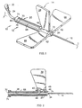
- FIG. 1 is a perspective view of a blood collection set in accordance with the subject invention.
- FIG. 2 is a cross-sectional view taken along line 2-2 in FIG. 1.
- FIG. 3 is a perspective view similar to FIG. 1, but showing the needle in a fully shielded position.
- Blood collection set 10 includes a needle assembly 12 which comprises a hub 14, a needle cannula 16, a safety shield 20 and a spring 22. Needle assembly 12 is used with a flexible tube 24 and a fitting 30. Fitting 30 can be connected to a reservoir into which blood drawn from needle assembly 12 may be deposited.
- Hub 14 includes a proximal end 32 connected to flexible tubing 24, a distal end 34 connected to needle cannula 16 and a tubular passage 36 extending therebetween, as shown in FIG. 2.
- Hub 14 further includes a dorsal fin 38 projecting unitarily outwardly from a portion of hub 14 intermediate proximal and distal ends 32 and 34.
- Dorsal fin 38 is connected to remaining portions of hub 14 by a narrow deflectable root 40.
- An actuator 42 projects outwardly from hub 14 at a location between root 40 of dorsal fin 38 and distal end 34 of hub 14. Actuator 42 is substantially registered with distal portions of dorsal fin 38. As a result, dorsal fin 38 can be deflected about root 40 and into contact with actuator 42.
- Actuator 42 has a proximal face 44 and a distal face 46 that is radially longer than proximal face 44.
- a ramp face 48 extends between proximal and distal faces 44 and 46.
- Shield 20 is an elongate tubular member having a proximal end 60 and a distal end 62.
- the inside diameter of shield 20 is greater than the sum of the hub 14 plus the radial length of distal face 46 of actuator 42.
- Shield 20 includes a pair of flexible wings 66 extending transversely therefrom.
- shield 20 includes an elongate slot 68 extending from proximal end 60 toward distal end 62 at a location that is angularly between fins 66.
- Slot 68 is dimensioned to slidably receive root 40 of dorsal fin 38.
- a pair of detents 70 are formed in slot 68 and extend toward one another at a location near the proximal end of shield 14.
- An annular closure 71 is mounted over proximal end 60 of shield 20 and closes the proximal end of slot 68 .
- a retention aperture 72 extends through shield 20 at a location aligned with slot 68 and slightly distally therefrom. The spacing between slot 68 and retention aperture 72 substantially equals the distance between root 40 and actuator 42. Additionally, retention aperture 72 is dimensioned to receive actuator 42 when dorsal fin 48 and root 40 are in a distal position in slot 42. Distal end 62 of shield 20 is formed with an inwardly extending flange 74. Spring 22 is positioned in shield 20 between inwardly extending flange 74 and actuator 42.
- Needle assembly 12 is assembled by initially sliding spring 22 into proximal end 60 of shield 20. Hub 14 then is slid into proximal end 60 of shield 20 such that root 40 of dorsal fin 38 is slidably received in slot 68. Annular closure 71 then is securely mounted over proximal end 60 of shield 20, such that proximal end 32 of hub 14 passes through the central aperture of annular closure 71. Hub 14 is slid distally in shield 20 until actuator 42 aligns with retention aperture 72 in shield 20. Engagement between actuator 42 and portions of shield 20 adjacent retention aperture 72 will releasably retain shield 20 in the proximal position shown in FIGS. 1 and 2 relative to hub 14. Needle cannula 16 will be covered by a safety cap (not shown) until immediately prior to use of blood collection set 10 .
- Blood collection set 10 is used by removing the safety cap and inserting needle cannula 16 into a patient in a conventional manner.
- Digital manipulation of needle assembly 12 can be facilitated by deflecting wings 66 toward one another to define a grip.
- needle cannula 16 is removed from the patient. Shielding is achieved merely by deflecting dorsal fin 38 in a distal direction and around root 40.
- Dorsal fin 38 will deflect into actuator 42 and will move actuator 42 transversely in shield 20 a sufficient distance for proximal face 44 to move inside the passage of shield 20.
- Spring 22 will then force ramp face 48 to ride over portions of shield 20 adjacent retention aperture 72 and will continue propelling hub 14 and shield 20 in opposite directions relative to one another.
- Root 40 then will advance proximally of detents 70, and will be lockingly retained at the extreme proximal end of slot 68 as shown in FIG. 3.
- Re-exposure of needle cannula 16 can be achieved only by significantly deforming and damaging shield 20, and cannot be achieved by mere inadvertence.
- deflection and then retention of dorsal fin 38 will cause shield 20 to be propelled distally.
- a user of the blood collection set 10 can hold onto wings 66 without holding onto dorsal fin 38. With this gripping, blood collection set 10 becomes a needle retracting device with hub 14 and needle cannula 16 being propelled in a proximal direction by spring 22.
Landscapes
- Health & Medical Sciences (AREA)
- Life Sciences & Earth Sciences (AREA)
- Heart & Thoracic Surgery (AREA)
- Surgery (AREA)
- Biophysics (AREA)
- Pathology (AREA)
- Engineering & Computer Science (AREA)
- Biomedical Technology (AREA)
- Hematology (AREA)
- Medical Informatics (AREA)
- Molecular Biology (AREA)
- Physics & Mathematics (AREA)
- Animal Behavior & Ethology (AREA)
- General Health & Medical Sciences (AREA)
- Public Health (AREA)
- Veterinary Medicine (AREA)
- Measurement Of The Respiration, Hearing Ability, Form, And Blood Characteristics Of Living Organisms (AREA)
- Infusion, Injection, And Reservoir Apparatuses (AREA)
- Media Introduction/Drainage Providing Device (AREA)
Claims (8)
- Nadelanordnung für ein Blutsammelset, mit:gekennzeichnet durcheinem Ansatz (14) mit entgegengesetzten proximalen und distalen Enden (32, 34) und einem sich zwischen den Enden erstreckenden Durchgang (36), wobei eine elastisch auslenkbare Rückenfinne (38) vom Ansatz nach außen vorsteht;einer Nadelkanüle (16) mit einem proximalen Ende, das mit dem distalen Ende des Ansatzes verbunden ist, einem distalen Ende und einem sich zwischen diesen erstreckenden Lumen, wobei das Lumen eine Fluidverbindung mit dem durch den Ansatz verlaufenden Durchgang herstellt;einem Schutz (20), der teleskopierbar über dem Ansatz und der Nadelkanüle derart angeordnet ist, daß der Schutz und/oder der Ansatz aus einer ersten Position, in weicher die Nadelkanüle frei liegt, in eine zweite Position bewegbar ist, in welcher die Nadelkanüle geschützt ist, wobei sich ein Schlitz (68) durch den Schutz erstreckt und einen Bereich der Rückenfinne gleitend verschiebbar aufnimmt, wobei ein Ende des Schlitzes derart ausgebildet ist, daß er an der Rückenfinne blockierend angreift, wenn sich der Schutz und der Ansatz in der zweiten Position befinden;eine zwischen Bereichen des Ansatzes und des Schutzes gehaltene Feder (22), welche zum Treiben des Schutzes und des Ansatzes in die zweite Position betreibbar ist; undeinen Halter (42) zum lösbaren Festhalten des Schutzes in der ersten Position, wobei der Halter von der Rückenfinne lösbar ist, um den Ansatz und den Schutz aus der ersten Position zu lösen und der Feder zu ermöglichen, den Schutz und/oder den Ansatz in zu zweite Position zu treiben.
- Nadelanordnung nach Anspruch 1, bei der die elastisch auslenkbare Rückenfinne eine schmale Wurzel (40) zum Verbinden der Rückenfinne mit dem Ansatz aufweist, wobei die Rückenfinne in bezug auf die Wurzel in proximaler und in distaler Richtung auslenkbar ist.
- Nadelanordnung nach Anspruch 2, bei der die Wurzel den Bereich der Rückenfinne bildet, der in den Schlitz eingreift.
- Nadelanordnung nach Anspruch 1, bei der der Schutz entgegengesetzte proximale und distale Enden aufweist, wobei sich der Schlitz von einer Stelle nahe dem proximalen Ende zu einer proximal dem distalen Ende gelegenen Stelle erstreckt, wobei Bereiche des Schlitzes, die distal vom proximalen Ende beabstandet sind, zwei Vorsprünge (70) zum Verengen des Schlitzes aufweisen, wobei das Bewegen des Schutzes und des Ansatzes in die zweite Position den Vorsprüngen ermöglichen, die Rückenfinne zwischen den Vorsprüngen und dem proximalen Ende des Schutzes blockierend festzulegen.
- Nadelanordnung nach Anspruch 4, bei der der Schutz ferner eine Rückhalteöffnung (72) aufweist, welche durch diesen hindurch an einer Stelle zwischen dem Schlitz und dem distalen Ende des Schutzes ausgebildet ist, wobei der Halter einen sich vom Ansatz aus erstreckenden Vorsprung aufweist, der sich in die Rückhalteöffnung des Schutzes erstreckt, wenn der Schutz und der Ansatz sich in der ersten Position befinden.
- Nadelanordnung nach Anspruch 5, bei der die Halteöffnung mit dem Schlitz ausgerichtet ist, und bei der die elastisch auslenkbare Rückenfinne zum Angreifen an dem Halter und zum Drücken des Halters aus der Rückhalteöffnung ausgebildet ist, wodurch es der Feder möglich ist, den Schutz und/oder den Ansatz in die zweite Position zu treiben.
- Nadelanordnung nach Anspruch 1, bei der der Schutz ferner zwei in Querrichtung von dem Schutz abstehende Flügel (66) aufweist.
- Nadelanordnung nach Anspruch 7, bei der die Flügel derart angeordnet sind, daß sie auf jeweils entgegengesetzte Seiten der Rückenfinne liegen, wenn der Schutz und der Ansatz sich in der ersten Position befinden.
Applications Claiming Priority (4)
| Application Number | Priority Date | Filing Date | Title |
|---|---|---|---|
| US25987501P | 2001-01-05 | 2001-01-05 | |
| US259875P | 2001-01-05 | ||
| US10/066,916 US6659984B2 (en) | 2001-01-05 | 2001-11-13 | Needle assembly |
| US66916 | 2001-11-13 |
Publications (3)
| Publication Number | Publication Date |
|---|---|
| EP1221300A2 EP1221300A2 (de) | 2002-07-10 |
| EP1221300A3 EP1221300A3 (de) | 2002-07-17 |
| EP1221300B1 true EP1221300B1 (de) | 2005-08-17 |
Family
ID=26747298
Family Applications (1)
| Application Number | Title | Priority Date | Filing Date |
|---|---|---|---|
| EP01128983A Expired - Lifetime EP1221300B1 (de) | 2001-01-05 | 2001-12-06 | Nadelanordnung |
Country Status (6)
| Country | Link |
|---|---|
| US (1) | US6659984B2 (de) |
| EP (1) | EP1221300B1 (de) |
| JP (1) | JP3958580B2 (de) |
| AU (1) | AU783338B2 (de) |
| CA (1) | CA2365065A1 (de) |
| DE (1) | DE60112704T2 (de) |
Families Citing this family (27)
| Publication number | Priority date | Publication date | Assignee | Title |
|---|---|---|---|---|
| US6984223B2 (en) * | 2001-11-13 | 2006-01-10 | Becton, Dickinson And Company | Needle safety device |
| US8066678B2 (en) | 2001-12-17 | 2011-11-29 | Bard Access Systems, Inc. | Safety needle with collapsible sheath |
| US7060053B2 (en) * | 2002-02-28 | 2006-06-13 | Medikit Co., Ltd. | Safety indwelling syringe |
| JP4209642B2 (ja) * | 2002-07-26 | 2009-01-14 | 川澄化学工業株式会社 | 針カバー及びキャップ付針カバー並びに針カバー付翼付針 |
| US20040176730A1 (en) * | 2002-08-13 | 2004-09-09 | Wang Hsien Tsung | Disposable, safe butterfly needle sheath |
| US7189218B2 (en) * | 2003-08-07 | 2007-03-13 | Edward Lichtenberg | Needle apparatus with quick/safe release mechanism |
| EP1661593A4 (de) * | 2003-08-11 | 2009-04-22 | Chang-Ming Yang | Schmetterlingsnadel-anordnung |
| US20050070849A1 (en) * | 2003-09-30 | 2005-03-31 | Chang-Ming Yang | Safety winged set |
| US7625357B2 (en) * | 2003-09-30 | 2009-12-01 | Chang-Ming Yang | Safety winged needle structure |
| CN2655924Y (zh) * | 2003-11-17 | 2004-11-17 | 杨章民 | 一次用安全针头护盖 |
| US7322963B2 (en) * | 2003-11-20 | 2008-01-29 | Jms Singapore Pte Ltd. | Telescopic safety arteriovenous fistula needle |
| US7776016B1 (en) | 2004-02-26 | 2010-08-17 | C. R. Bard, Inc. | Huber needle safety enclosure |
| MX2007010945A (es) * | 2005-03-07 | 2008-02-20 | Erskine Medical Llc | Aguja con alas con proteccion de aguja. |
| NZ566616A (en) * | 2005-09-22 | 2011-01-28 | Tyco Healthcare | Manually retracted safety needle with rigid wing structure and pivotable catch on hub to engage housing |
| US8597253B2 (en) | 2007-04-20 | 2013-12-03 | Bard Access Systems | Huber needle with safety sheath |
| US8439870B2 (en) | 2008-09-10 | 2013-05-14 | B. Braun Medical Inc. | Safety needle assembly and methods |
| US8231582B2 (en) | 2008-12-11 | 2012-07-31 | Bard Access Systems, Inc. | Device for removing a Huber needle from a patient |
| WO2012023938A1 (en) | 2010-08-19 | 2012-02-23 | West Pharmaceutical Services, Inc. | Rigid needle shield |
| US10525234B2 (en) | 2010-09-10 | 2020-01-07 | C. R. Bard, Inc. | Antimicrobial/haemostatic interface pad for placement between percutaneously placed medical device and patient skin |
| US9248234B2 (en) | 2010-09-10 | 2016-02-02 | C. R. Bard, Inc. | Systems for isolation of a needle-based infusion set |
| US20140066894A1 (en) | 2010-09-10 | 2014-03-06 | C. R. Bard, Inc. | Self-Sealing Pad for a Needle-Based Infusion Set |
| MY161285A (en) | 2010-12-02 | 2017-04-14 | Erskine Medical Llc | Release mechanism for use with needle shielding devices |
| CA2822982C (en) | 2010-12-02 | 2016-01-19 | Erskine Medical Llc | Needle shield assembly with hub engagement member for needle device |
| MX376645B (es) | 2011-04-07 | 2025-03-07 | Erskine Medical Llc | Dispositivo de blindaje de aguja. |
| US9861784B2 (en) * | 2013-12-03 | 2018-01-09 | Becton, Dickinson And Company | Blood collection device with double pivot shields |
| US9370327B2 (en) * | 2014-01-28 | 2016-06-21 | B. Braun Melsungen Ag | Medical devices with retractable needle and related methods |
| PT3045113T (pt) | 2014-04-11 | 2018-05-28 | Shanghai Jinta Medical Co Ltd | Placa de isolamento térmico |
Family Cites Families (14)
| Publication number | Priority date | Publication date | Assignee | Title |
|---|---|---|---|---|
| JPH03158171A (ja) * | 1989-11-17 | 1991-07-08 | Masataka Saito | キャップ一体型使い捨て注射針 |
| US5279581A (en) | 1990-05-09 | 1994-01-18 | Firth John R | Disposable self-shielding hypodermic syringe |
| FR2666230B1 (fr) | 1990-09-03 | 1997-10-03 | Hospal Ind | Dispositif a aiguille a usage medical. |
| EP0545671B1 (de) * | 1991-12-03 | 1999-03-03 | Smiths Industries Plc | Nadelschutzvorrichtung |
| US5330438A (en) | 1993-10-08 | 1994-07-19 | Gollobin Peter J | Protective sheath for butterfly needles and IV infusion set and sheath assembly |
| US5498241A (en) | 1994-12-08 | 1996-03-12 | Abbott Laboratories | Winged needle assembly with protective member |
| ATE286754T1 (de) | 1997-03-26 | 2005-01-15 | Bio Plexus Inc | Vorrichtung zum überleiten einer parenteralen flüssigkeit |
| US5779679A (en) * | 1997-04-18 | 1998-07-14 | Shaw; Thomas J. | Winged IV set with retractable needle |
| ATE270124T1 (de) | 1997-04-30 | 2004-07-15 | Michela Bragaglia | Intravenöse infusionsvorrichtung |
| ES2284218T3 (es) * | 1997-11-12 | 2007-11-01 | Mdc Investment Holdings, Inc. | Dispositivo para la recogida de fluidos con aguja retractil capturada. |
| JP2000237174A (ja) * | 1999-02-23 | 2000-09-05 | Mitsubishi Pencil Co Ltd | 穿刺具 |
| GB9903974D0 (en) | 1998-11-04 | 1999-04-14 | Choudhary Prajendra P | Needle assembly |
| US6302868B1 (en) | 1998-12-22 | 2001-10-16 | Owais Mohammad | Retractable hypodermic needle assembly and method of making the same |
| JP4003223B2 (ja) * | 1999-07-22 | 2007-11-07 | ニプロ株式会社 | 先端ガード付き留置針 |
-
2001
- 2001-11-13 US US10/066,916 patent/US6659984B2/en not_active Expired - Lifetime
- 2001-12-06 DE DE60112704T patent/DE60112704T2/de not_active Expired - Lifetime
- 2001-12-06 EP EP01128983A patent/EP1221300B1/de not_active Expired - Lifetime
- 2001-12-17 CA CA002365065A patent/CA2365065A1/en not_active Abandoned
- 2001-12-28 AU AU97496/01A patent/AU783338B2/en not_active Ceased
-
2002
- 2002-01-07 JP JP2002000909A patent/JP3958580B2/ja not_active Expired - Lifetime
Also Published As
| Publication number | Publication date |
|---|---|
| DE60112704T2 (de) | 2006-06-08 |
| US20020099340A1 (en) | 2002-07-25 |
| AU9749601A (en) | 2002-07-11 |
| EP1221300A3 (de) | 2002-07-17 |
| AU783338B2 (en) | 2005-10-20 |
| US6659984B2 (en) | 2003-12-09 |
| JP2002325752A (ja) | 2002-11-12 |
| DE60112704D1 (de) | 2005-09-22 |
| JP3958580B2 (ja) | 2007-08-15 |
| EP1221300A2 (de) | 2002-07-10 |
| CA2365065A1 (en) | 2002-07-05 |
Similar Documents
| Publication | Publication Date | Title |
|---|---|---|
| EP1221300B1 (de) | Nadelanordnung | |
| EP1221301B1 (de) | Blutsammelsatz | |
| US6673047B2 (en) | Blood collection set | |
| US6743186B2 (en) | Blood collection assembly | |
| US6659983B2 (en) | Needle assembly | |
| US7722564B2 (en) | Needle guard | |
| EP1221304A2 (de) | Blutabnahmevorrichtung | |
| EP1449554A1 (de) | Passive Sicherheitsvorrichtung für die Nadel eines Infusions -oder Bloodnahme-Sets | |
| CA2364963A1 (en) | Blood collection set | |
| CA2364972A1 (en) | Blood collection set | |
| CA2366993A1 (en) | Blood collection set with retractable needle | |
| CA2366864A1 (en) | Blood collection assembly |
Legal Events
| Date | Code | Title | Description |
|---|---|---|---|
| PUAI | Public reference made under article 153(3) epc to a published international application that has entered the european phase |
Free format text: ORIGINAL CODE: 0009012 |
|
| PUAL | Search report despatched |
Free format text: ORIGINAL CODE: 0009013 |
|
| AK | Designated contracting states |
Kind code of ref document: A2 Designated state(s): AT BE CH CY DE DK ES FI FR GB GR IE IT LI LU MC NL PT SE TR |
|
| AX | Request for extension of the european patent |
Free format text: AL;LT;LV;MK;RO;SI |
|
| AK | Designated contracting states |
Kind code of ref document: A3 Designated state(s): AT BE CH CY DE DK ES FI FR GB GR IE IT LI LU MC NL PT SE TR |
|
| AX | Request for extension of the european patent |
Free format text: AL;LT;LV;MK;RO;SI |
|
| 17P | Request for examination filed |
Effective date: 20020816 |
|
| AKX | Designation fees paid |
Designated state(s): DE FR GB IT |
|
| GRAP | Despatch of communication of intention to grant a patent |
Free format text: ORIGINAL CODE: EPIDOSNIGR1 |
|
| GRAS | Grant fee paid |
Free format text: ORIGINAL CODE: EPIDOSNIGR3 |
|
| GRAA | (expected) grant |
Free format text: ORIGINAL CODE: 0009210 |
|
| AK | Designated contracting states |
Kind code of ref document: B1 Designated state(s): DE FR GB IT |
|
| REG | Reference to a national code |
Ref country code: GB Ref legal event code: FG4D |
|
| REF | Corresponds to: |
Ref document number: 60112704 Country of ref document: DE Date of ref document: 20050922 Kind code of ref document: P |
|
| ET | Fr: translation filed | ||
| PLBE | No opposition filed within time limit |
Free format text: ORIGINAL CODE: 0009261 |
|
| STAA | Information on the status of an ep patent application or granted ep patent |
Free format text: STATUS: NO OPPOSITION FILED WITHIN TIME LIMIT |
|
| 26N | No opposition filed |
Effective date: 20060518 |
|
| PGFP | Annual fee paid to national office [announced via postgrant information from national office to epo] |
Ref country code: FR Payment date: 20061220 Year of fee payment: 6 |
|
| PGFP | Annual fee paid to national office [announced via postgrant information from national office to epo] |
Ref country code: GB Payment date: 20061222 Year of fee payment: 6 |
|
| PGFP | Annual fee paid to national office [announced via postgrant information from national office to epo] |
Ref country code: IT Payment date: 20061231 Year of fee payment: 6 |
|
| GBPC | Gb: european patent ceased through non-payment of renewal fee |
Effective date: 20071206 |
|
| REG | Reference to a national code |
Ref country code: FR Ref legal event code: ST Effective date: 20081020 |
|
| PG25 | Lapsed in a contracting state [announced via postgrant information from national office to epo] |
Ref country code: GB Free format text: LAPSE BECAUSE OF NON-PAYMENT OF DUE FEES Effective date: 20071206 |
|
| PG25 | Lapsed in a contracting state [announced via postgrant information from national office to epo] |
Ref country code: FR Free format text: LAPSE BECAUSE OF NON-PAYMENT OF DUE FEES Effective date: 20071231 |
|
| PG25 | Lapsed in a contracting state [announced via postgrant information from national office to epo] |
Ref country code: IT Free format text: LAPSE BECAUSE OF NON-PAYMENT OF DUE FEES Effective date: 20071206 |
|
| PGFP | Annual fee paid to national office [announced via postgrant information from national office to epo] |
Ref country code: DE Payment date: 20201119 Year of fee payment: 20 |
|
| REG | Reference to a national code |
Ref country code: DE Ref legal event code: R071 Ref document number: 60112704 Country of ref document: DE |