EP1221394A1 - Regel vorrichtung fur ein hybrid fahrzeug - Google Patents
Regel vorrichtung fur ein hybrid fahrzeug Download PDFInfo
- Publication number
- EP1221394A1 EP1221394A1 EP00951884A EP00951884A EP1221394A1 EP 1221394 A1 EP1221394 A1 EP 1221394A1 EP 00951884 A EP00951884 A EP 00951884A EP 00951884 A EP00951884 A EP 00951884A EP 1221394 A1 EP1221394 A1 EP 1221394A1
- Authority
- EP
- European Patent Office
- Prior art keywords
- engine
- vibration damping
- electric motor
- stored charge
- condition
- Prior art date
- Legal status (The legal status is an assumption and is not a legal conclusion. Google has not performed a legal analysis and makes no representation as to the accuracy of the status listed.)
- Granted
Links
Images





Classifications
-
- B—PERFORMING OPERATIONS; TRANSPORTING
- B60—VEHICLES IN GENERAL
- B60K—ARRANGEMENT OR MOUNTING OF PROPULSION UNITS OR OF TRANSMISSIONS IN VEHICLES; ARRANGEMENT OR MOUNTING OF PLURAL DIVERSE PRIME-MOVERS IN VEHICLES; AUXILIARY DRIVES FOR VEHICLES; INSTRUMENTATION OR DASHBOARDS FOR VEHICLES; ARRANGEMENTS IN CONNECTION WITH COOLING, AIR INTAKE, GAS EXHAUST OR FUEL SUPPLY OF PROPULSION UNITS IN VEHICLES
- B60K6/00—Arrangement or mounting of plural diverse prime-movers for mutual or common propulsion, e.g. hybrid propulsion systems comprising electric motors and internal combustion engines
- B60K6/20—Arrangement or mounting of plural diverse prime-movers for mutual or common propulsion, e.g. hybrid propulsion systems comprising electric motors and internal combustion engines the prime-movers consisting of electric motors and internal combustion engines, e.g. HEVs
- B60K6/42—Arrangement or mounting of plural diverse prime-movers for mutual or common propulsion, e.g. hybrid propulsion systems comprising electric motors and internal combustion engines the prime-movers consisting of electric motors and internal combustion engines, e.g. HEVs characterised by the architecture of the hybrid electric vehicle
- B60K6/48—Parallel type
- B60K6/485—Motor-assist type
-
- B—PERFORMING OPERATIONS; TRANSPORTING
- B60—VEHICLES IN GENERAL
- B60L—PROPULSION OF ELECTRICALLY-PROPELLED VEHICLES; SUPPLYING ELECTRIC POWER FOR AUXILIARY EQUIPMENT OF ELECTRICALLY-PROPELLED VEHICLES; ELECTRODYNAMIC BRAKE SYSTEMS FOR VEHICLES IN GENERAL; MAGNETIC SUSPENSION OR LEVITATION FOR VEHICLES; MONITORING OPERATING VARIABLES OF ELECTRICALLY-PROPELLED VEHICLES; ELECTRIC SAFETY DEVICES FOR ELECTRICALLY-PROPELLED VEHICLES
- B60L50/00—Electric propulsion with power supplied within the vehicle
- B60L50/10—Electric propulsion with power supplied within the vehicle using propulsion power supplied by engine-driven generators, e.g. generators driven by combustion engines
- B60L50/16—Electric propulsion with power supplied within the vehicle using propulsion power supplied by engine-driven generators, e.g. generators driven by combustion engines with provision for separate direct mechanical propulsion
-
- B—PERFORMING OPERATIONS; TRANSPORTING
- B60—VEHICLES IN GENERAL
- B60W—CONJOINT CONTROL OF VEHICLE SUB-UNITS OF DIFFERENT TYPE OR DIFFERENT FUNCTION; CONTROL SYSTEMS SPECIALLY ADAPTED FOR HYBRID VEHICLES; ROAD VEHICLE DRIVE CONTROL SYSTEMS FOR PURPOSES NOT RELATED TO THE CONTROL OF A PARTICULAR SUB-UNIT
- B60W20/00—Control systems specially adapted for hybrid vehicles
- B60W20/10—Controlling the power contribution of each of the prime movers to meet required power demand
- B60W20/15—Control strategies specially adapted for achieving a particular effect
-
- B—PERFORMING OPERATIONS; TRANSPORTING
- B60—VEHICLES IN GENERAL
- B60L—PROPULSION OF ELECTRICALLY-PROPELLED VEHICLES; SUPPLYING ELECTRIC POWER FOR AUXILIARY EQUIPMENT OF ELECTRICALLY-PROPELLED VEHICLES; ELECTRODYNAMIC BRAKE SYSTEMS FOR VEHICLES IN GENERAL; MAGNETIC SUSPENSION OR LEVITATION FOR VEHICLES; MONITORING OPERATING VARIABLES OF ELECTRICALLY-PROPELLED VEHICLES; ELECTRIC SAFETY DEVICES FOR ELECTRICALLY-PROPELLED VEHICLES
- B60L1/00—Supplying electric power to auxiliary equipment of vehicles
-
- B—PERFORMING OPERATIONS; TRANSPORTING
- B60—VEHICLES IN GENERAL
- B60L—PROPULSION OF ELECTRICALLY-PROPELLED VEHICLES; SUPPLYING ELECTRIC POWER FOR AUXILIARY EQUIPMENT OF ELECTRICALLY-PROPELLED VEHICLES; ELECTRODYNAMIC BRAKE SYSTEMS FOR VEHICLES IN GENERAL; MAGNETIC SUSPENSION OR LEVITATION FOR VEHICLES; MONITORING OPERATING VARIABLES OF ELECTRICALLY-PROPELLED VEHICLES; ELECTRIC SAFETY DEVICES FOR ELECTRICALLY-PROPELLED VEHICLES
- B60L50/00—Electric propulsion with power supplied within the vehicle
- B60L50/10—Electric propulsion with power supplied within the vehicle using propulsion power supplied by engine-driven generators, e.g. generators driven by combustion engines
- B60L50/15—Electric propulsion with power supplied within the vehicle using propulsion power supplied by engine-driven generators, e.g. generators driven by combustion engines with additional electric power supply
-
- B—PERFORMING OPERATIONS; TRANSPORTING
- B60—VEHICLES IN GENERAL
- B60L—PROPULSION OF ELECTRICALLY-PROPELLED VEHICLES; SUPPLYING ELECTRIC POWER FOR AUXILIARY EQUIPMENT OF ELECTRICALLY-PROPELLED VEHICLES; ELECTRODYNAMIC BRAKE SYSTEMS FOR VEHICLES IN GENERAL; MAGNETIC SUSPENSION OR LEVITATION FOR VEHICLES; MONITORING OPERATING VARIABLES OF ELECTRICALLY-PROPELLED VEHICLES; ELECTRIC SAFETY DEVICES FOR ELECTRICALLY-PROPELLED VEHICLES
- B60L58/00—Methods or circuit arrangements for monitoring or controlling batteries or fuel cells, specially adapted for electric vehicles
- B60L58/10—Methods or circuit arrangements for monitoring or controlling batteries or fuel cells, specially adapted for electric vehicles for monitoring or controlling batteries
-
- B—PERFORMING OPERATIONS; TRANSPORTING
- B60—VEHICLES IN GENERAL
- B60W—CONJOINT CONTROL OF VEHICLE SUB-UNITS OF DIFFERENT TYPE OR DIFFERENT FUNCTION; CONTROL SYSTEMS SPECIALLY ADAPTED FOR HYBRID VEHICLES; ROAD VEHICLE DRIVE CONTROL SYSTEMS FOR PURPOSES NOT RELATED TO THE CONTROL OF A PARTICULAR SUB-UNIT
- B60W10/00—Conjoint control of vehicle sub-units of different type or different function
- B60W10/04—Conjoint control of vehicle sub-units of different type or different function including control of propulsion units
- B60W10/06—Conjoint control of vehicle sub-units of different type or different function including control of propulsion units including control of combustion engines
-
- B—PERFORMING OPERATIONS; TRANSPORTING
- B60—VEHICLES IN GENERAL
- B60W—CONJOINT CONTROL OF VEHICLE SUB-UNITS OF DIFFERENT TYPE OR DIFFERENT FUNCTION; CONTROL SYSTEMS SPECIALLY ADAPTED FOR HYBRID VEHICLES; ROAD VEHICLE DRIVE CONTROL SYSTEMS FOR PURPOSES NOT RELATED TO THE CONTROL OF A PARTICULAR SUB-UNIT
- B60W10/00—Conjoint control of vehicle sub-units of different type or different function
- B60W10/04—Conjoint control of vehicle sub-units of different type or different function including control of propulsion units
- B60W10/08—Conjoint control of vehicle sub-units of different type or different function including control of propulsion units including control of electric propulsion units, e.g. motors or generators
-
- B—PERFORMING OPERATIONS; TRANSPORTING
- B60—VEHICLES IN GENERAL
- B60W—CONJOINT CONTROL OF VEHICLE SUB-UNITS OF DIFFERENT TYPE OR DIFFERENT FUNCTION; CONTROL SYSTEMS SPECIALLY ADAPTED FOR HYBRID VEHICLES; ROAD VEHICLE DRIVE CONTROL SYSTEMS FOR PURPOSES NOT RELATED TO THE CONTROL OF A PARTICULAR SUB-UNIT
- B60W10/00—Conjoint control of vehicle sub-units of different type or different function
- B60W10/24—Conjoint control of vehicle sub-units of different type or different function including control of energy storage means
- B60W10/26—Conjoint control of vehicle sub-units of different type or different function including control of energy storage means for electrical energy, e.g. batteries or capacitors
-
- B—PERFORMING OPERATIONS; TRANSPORTING
- B60—VEHICLES IN GENERAL
- B60W—CONJOINT CONTROL OF VEHICLE SUB-UNITS OF DIFFERENT TYPE OR DIFFERENT FUNCTION; CONTROL SYSTEMS SPECIALLY ADAPTED FOR HYBRID VEHICLES; ROAD VEHICLE DRIVE CONTROL SYSTEMS FOR PURPOSES NOT RELATED TO THE CONTROL OF A PARTICULAR SUB-UNIT
- B60W30/00—Purposes of road vehicle drive control systems not related to the control of a particular sub-unit, e.g. of systems using conjoint control of vehicle sub-units
- B60W30/18—Propelling the vehicle
- B60W30/20—Reducing vibrations in the driveline
-
- F—MECHANICAL ENGINEERING; LIGHTING; HEATING; WEAPONS; BLASTING
- F02—COMBUSTION ENGINES; HOT-GAS OR COMBUSTION-PRODUCT ENGINE PLANTS
- F02D—CONTROLLING COMBUSTION ENGINES
- F02D29/00—Controlling engines, such controlling being peculiar to the devices driven thereby, the devices being other than parts or accessories essential to engine operation, e.g. controlling of engines by signals external thereto
- F02D29/06—Controlling engines, such controlling being peculiar to the devices driven thereby, the devices being other than parts or accessories essential to engine operation, e.g. controlling of engines by signals external thereto peculiar to engines driving electric generators
-
- F—MECHANICAL ENGINEERING; LIGHTING; HEATING; WEAPONS; BLASTING
- F02—COMBUSTION ENGINES; HOT-GAS OR COMBUSTION-PRODUCT ENGINE PLANTS
- F02D—CONTROLLING COMBUSTION ENGINES
- F02D41/00—Electrical control of supply of combustible mixture or its constituents
- F02D41/02—Circuit arrangements for generating control signals
- F02D41/04—Introducing corrections for particular operating conditions
- F02D41/08—Introducing corrections for particular operating conditions for idling
- F02D41/083—Introducing corrections for particular operating conditions for idling taking into account engine load variation, e.g. air-conditionning
-
- F—MECHANICAL ENGINEERING; LIGHTING; HEATING; WEAPONS; BLASTING
- F02—COMBUSTION ENGINES; HOT-GAS OR COMBUSTION-PRODUCT ENGINE PLANTS
- F02D—CONTROLLING COMBUSTION ENGINES
- F02D41/00—Electrical control of supply of combustible mixture or its constituents
- F02D41/02—Circuit arrangements for generating control signals
- F02D41/14—Introducing closed-loop corrections
- F02D41/1497—With detection of the mechanical response of the engine
- F02D41/1498—With detection of the mechanical response of the engine measuring engine roughness
-
- B—PERFORMING OPERATIONS; TRANSPORTING
- B60—VEHICLES IN GENERAL
- B60W—CONJOINT CONTROL OF VEHICLE SUB-UNITS OF DIFFERENT TYPE OR DIFFERENT FUNCTION; CONTROL SYSTEMS SPECIALLY ADAPTED FOR HYBRID VEHICLES; ROAD VEHICLE DRIVE CONTROL SYSTEMS FOR PURPOSES NOT RELATED TO THE CONTROL OF A PARTICULAR SUB-UNIT
- B60W20/00—Control systems specially adapted for hybrid vehicles
-
- B—PERFORMING OPERATIONS; TRANSPORTING
- B60—VEHICLES IN GENERAL
- B60W—CONJOINT CONTROL OF VEHICLE SUB-UNITS OF DIFFERENT TYPE OR DIFFERENT FUNCTION; CONTROL SYSTEMS SPECIALLY ADAPTED FOR HYBRID VEHICLES; ROAD VEHICLE DRIVE CONTROL SYSTEMS FOR PURPOSES NOT RELATED TO THE CONTROL OF A PARTICULAR SUB-UNIT
- B60W2510/00—Input parameters relating to a particular sub-units
- B60W2510/06—Combustion engines, Gas turbines
- B60W2510/0638—Engine speed
-
- B—PERFORMING OPERATIONS; TRANSPORTING
- B60—VEHICLES IN GENERAL
- B60W—CONJOINT CONTROL OF VEHICLE SUB-UNITS OF DIFFERENT TYPE OR DIFFERENT FUNCTION; CONTROL SYSTEMS SPECIALLY ADAPTED FOR HYBRID VEHICLES; ROAD VEHICLE DRIVE CONTROL SYSTEMS FOR PURPOSES NOT RELATED TO THE CONTROL OF A PARTICULAR SUB-UNIT
- B60W2510/00—Input parameters relating to a particular sub-units
- B60W2510/24—Energy storage means
- B60W2510/242—Energy storage means for electrical energy
- B60W2510/244—Charge state
-
- B—PERFORMING OPERATIONS; TRANSPORTING
- B60—VEHICLES IN GENERAL
- B60W—CONJOINT CONTROL OF VEHICLE SUB-UNITS OF DIFFERENT TYPE OR DIFFERENT FUNCTION; CONTROL SYSTEMS SPECIALLY ADAPTED FOR HYBRID VEHICLES; ROAD VEHICLE DRIVE CONTROL SYSTEMS FOR PURPOSES NOT RELATED TO THE CONTROL OF A PARTICULAR SUB-UNIT
- B60W2710/00—Output or target parameters relating to a particular sub-units
- B60W2710/06—Combustion engines, Gas turbines
- B60W2710/0644—Engine speed
- B60W2710/065—Idle condition
-
- F—MECHANICAL ENGINEERING; LIGHTING; HEATING; WEAPONS; BLASTING
- F02—COMBUSTION ENGINES; HOT-GAS OR COMBUSTION-PRODUCT ENGINE PLANTS
- F02D—CONTROLLING COMBUSTION ENGINES
- F02D2200/00—Input parameters for engine control
- F02D2200/02—Input parameters for engine control the parameters being related to the engine
- F02D2200/04—Engine intake system parameters
- F02D2200/0406—Intake manifold pressure
-
- F—MECHANICAL ENGINEERING; LIGHTING; HEATING; WEAPONS; BLASTING
- F02—COMBUSTION ENGINES; HOT-GAS OR COMBUSTION-PRODUCT ENGINE PLANTS
- F02D—CONTROLLING COMBUSTION ENGINES
- F02D2200/00—Input parameters for engine control
- F02D2200/02—Input parameters for engine control the parameters being related to the engine
- F02D2200/10—Parameters related to the engine output, e.g. engine torque or engine speed
- F02D2200/1015—Engines misfires
-
- F—MECHANICAL ENGINEERING; LIGHTING; HEATING; WEAPONS; BLASTING
- F02—COMBUSTION ENGINES; HOT-GAS OR COMBUSTION-PRODUCT ENGINE PLANTS
- F02D—CONTROLLING COMBUSTION ENGINES
- F02D2200/00—Input parameters for engine control
- F02D2200/50—Input parameters for engine control said parameters being related to the vehicle or its components
- F02D2200/503—Battery correction, i.e. corrections as a function of the state of the battery, its output or its type
-
- F—MECHANICAL ENGINEERING; LIGHTING; HEATING; WEAPONS; BLASTING
- F02—COMBUSTION ENGINES; HOT-GAS OR COMBUSTION-PRODUCT ENGINE PLANTS
- F02D—CONTROLLING COMBUSTION ENGINES
- F02D2250/00—Engine control related to specific problems or objectives
- F02D2250/18—Control of the engine output torque
- F02D2250/24—Control of the engine output torque by using an external load, e.g. a generator
-
- F—MECHANICAL ENGINEERING; LIGHTING; HEATING; WEAPONS; BLASTING
- F02—COMBUSTION ENGINES; HOT-GAS OR COMBUSTION-PRODUCT ENGINE PLANTS
- F02D—CONTROLLING COMBUSTION ENGINES
- F02D2400/00—Control systems adapted for specific engine types; Special features of engine control systems not otherwise provided for; Power supply, connectors or cabling for engine control systems
- F02D2400/14—Power supply for engine control systems
-
- F—MECHANICAL ENGINEERING; LIGHTING; HEATING; WEAPONS; BLASTING
- F02—COMBUSTION ENGINES; HOT-GAS OR COMBUSTION-PRODUCT ENGINE PLANTS
- F02D—CONTROLLING COMBUSTION ENGINES
- F02D2400/00—Control systems adapted for specific engine types; Special features of engine control systems not otherwise provided for; Power supply, connectors or cabling for engine control systems
- F02D2400/16—Adaptation of engine control systems to a different battery voltages, e.g. for using high voltage batteries
-
- Y—GENERAL TAGGING OF NEW TECHNOLOGICAL DEVELOPMENTS; GENERAL TAGGING OF CROSS-SECTIONAL TECHNOLOGIES SPANNING OVER SEVERAL SECTIONS OF THE IPC; TECHNICAL SUBJECTS COVERED BY FORMER USPC CROSS-REFERENCE ART COLLECTIONS [XRACs] AND DIGESTS
- Y02—TECHNOLOGIES OR APPLICATIONS FOR MITIGATION OR ADAPTATION AGAINST CLIMATE CHANGE
- Y02T—CLIMATE CHANGE MITIGATION TECHNOLOGIES RELATED TO TRANSPORTATION
- Y02T10/00—Road transport of goods or passengers
- Y02T10/60—Other road transportation technologies with climate change mitigation effect
- Y02T10/62—Hybrid vehicles
-
- Y—GENERAL TAGGING OF NEW TECHNOLOGICAL DEVELOPMENTS; GENERAL TAGGING OF CROSS-SECTIONAL TECHNOLOGIES SPANNING OVER SEVERAL SECTIONS OF THE IPC; TECHNICAL SUBJECTS COVERED BY FORMER USPC CROSS-REFERENCE ART COLLECTIONS [XRACs] AND DIGESTS
- Y02—TECHNOLOGIES OR APPLICATIONS FOR MITIGATION OR ADAPTATION AGAINST CLIMATE CHANGE
- Y02T—CLIMATE CHANGE MITIGATION TECHNOLOGIES RELATED TO TRANSPORTATION
- Y02T10/00—Road transport of goods or passengers
- Y02T10/60—Other road transportation technologies with climate change mitigation effect
- Y02T10/70—Energy storage systems for electromobility, e.g. batteries
-
- Y—GENERAL TAGGING OF NEW TECHNOLOGICAL DEVELOPMENTS; GENERAL TAGGING OF CROSS-SECTIONAL TECHNOLOGIES SPANNING OVER SEVERAL SECTIONS OF THE IPC; TECHNICAL SUBJECTS COVERED BY FORMER USPC CROSS-REFERENCE ART COLLECTIONS [XRACs] AND DIGESTS
- Y02—TECHNOLOGIES OR APPLICATIONS FOR MITIGATION OR ADAPTATION AGAINST CLIMATE CHANGE
- Y02T—CLIMATE CHANGE MITIGATION TECHNOLOGIES RELATED TO TRANSPORTATION
- Y02T10/00—Road transport of goods or passengers
- Y02T10/60—Other road transportation technologies with climate change mitigation effect
- Y02T10/7072—Electromobility specific charging systems or methods for batteries, ultracapacitors, supercapacitors or double-layer capacitors
Definitions
- the present invention relates to a control apparatus for a hybrid vehicle in which a propulsion force for running the vehicle is generated by output from an engine assisted by an electric motor as required.
- One type of such hybrid vehicle is a parallel hybrid vehicle wherein an electric motor rotated by electricity is used as an auxiliary drive source for assisting the output from an engine, being an internal combustion engine.
- various control is carried out, such as assisting the output from the engine by means of the electric motor at the time of acceleration for example, and charging a battery by deceleration regeneration at the time of deceleration, so that the stored charge of the battery can be maintained while satisfying the requirements of the driver.
- An engine being an internal combustion engine, sometimes generates unpleasant vibrations at the time of low speed, that is, when idling.
- an electric motor that can reliably control torque electrically is incorporated into the engine, so that the engine vibration can be suppressed by controlling the torque of this electric motor.
- the present inventor has filed a first application for an engine vibration damping apparatus using such an electric motor (Japanese Unexamined Patent Application, First Publication No. Hei 9-248374).
- Such an engine vibration control apparatus generates a plurality of different sine waves in proportion to the rotational frequency of the engine output shaft depending on the running conditions of the engine, generates a composite wave of these sine waves as a torque waveform for the electric motor to generate to reduce the torque variation of the engine output shaft, and controls the vibration by controlling the electric motor according to this composite wave torque waveform.
- some energy may be consumed.
- vibration damping control is performed at the time of idling for example, depending on the state of power being consumed elsewhere in a vehicle, such as lighting, wiper operation, or furthermore the operation of a car stereo or the like, the electric power supply generated by the engine may be insufficient, and the deficiency is drawn from the electric motor battery, resulting in the stored charge of the electric motor battery being reduced. In this manner, if the stored charge of the electric motor battery is reduced, assistance cannot be given to the engine even if the conditions require it.
- the present invention takes into consideration the above situation, with an object of providing a control apparatus for a hybrid vehicle that prevents a situation in which a stored charge of an electric motor battery is reduced below a minimum required due to the vibration damping control device being operated, in other words, priority is given to preventing the stored charge of the electric motor battery being reduced below the minimum required, so that the occurrence of a situation that requires assistance to the engine by the electric motor can be handled without fail.
- the present invention has an object of providing a control apparatus for a hybrid vehicle that can prevent the stored charge of the electric motor battery from being reduced below the minimum required at the time of idling, and additionally can increase the stored charge.
- vibration damping control for controlling engine vibration by the electric motor is performed through a vibration damping device (for example, a power drive unit 16 in the embodiment).
- a second aspect of the invention is characterized in that conditions for permitting operation of vibration damping control require that, in addition to a stored charge of the electric motor battery detected by the storage state monitoring device being greater than a predetermined stored charge threshold (for example, a determination of step S9 in the embodiment), the vehicle is idling (for example, a determination of step S1 of the embodiment), engine speed is within a prescribed range (for example, a determination of step S5 in the embodiment), and engine load is within a prescribed range (for example, a determination of step S6 in the embodiment), and vibration damping control is performed when all conditions are satisfied.
- a predetermined stored charge threshold for example, a determination of step S9 in the embodiment
- the vehicle is idling
- engine speed is within a prescribed range
- engine load is within a prescribed range (for example, a determination of step S6 in the embodiment)
- vibration damping control is performed when all conditions are satisfied.
- a third aspect of the invention is characterized in that conditions for permitting operation of the vibration damping device require that an electrical load of the vehicle excluding the electric motor is greater than a predetermined electrical load threshold (for example, a determination of step S10 in the embodiment), and when the electrical load exceeds the predetermined electrical load threshold, vibration damping control by the vibration damping device is performed for a predetermined limited time (for example, step S12 in the embodiment), and conversely, when the electrical load is less than or equal to the predetermined electrical load threshold, vibration damping control by the vibration damping device is performed without any set time limit (for example, step S11 in the embodiment).
- a predetermined electrical load threshold for example, a determination of step S10 in the embodiment
- vibration damping control can be performed only for a predetermined limited time. Accordingly, it is possible to prevent a situation in which the amount of electric power drawn from the electric motor battery is increased and the stored charge of the electric motor battery reduced, due to performing vibration damping control over a long time.
- a fourth aspect of the invention is characterized in that when the electrical load exceeds a predetermined electrical load threshold, and vibration damping control by the vibration damping device is performed for a predetermined limited time, engine speed is increased as an elapsed time of vibration damping control increases (for example, steps S13, S15 and S17 in the embodiment).
- a fifth aspect of the invention is characterized in that when increasing engine speed, this is increased in stages as the elapsed time of vibration damping control increases (for example, steps S13, S15 and S17).
- vibration damping control is discontinued after a predetermined time has passed, since the engine speed is increased in stages, and vibration damping control is discontinued in a state of lower sensation of vibration, occupants experience little unpleasant sensation caused by engine vibration.
- vibration damping control is discontinued when the engine speed is low, the difference in vibration felt physically between when vibration damping control is performed and when not performed is considerable, so that the unpleasant sensation experienced by occupants increases when vibration damping control is discontinued.
- a sixth aspect of the invention is characterized in that when the engine is idling (for example, a determination of step SA1 in the embodiment), when the stored charge detected by the storage state monitoring device is greater (for example, a determination of step SA8 in the embodiment) than a predetermined stored charge threshold (for example, a first threshold value in the embodiment), vibration damping control for controlling the vibration damping of the engine is performed by the electric motor (for example, processing of step SA14 in the embodiment), and conversely, when the stored charge of the battery is less than or equal to the stored charge threshold value (for example, a determination of step SA8 in the embodiment), vibration damping control by the electric motor is inhibited (for example, processing of step SA10 in the embodiment), and when the stored charge of the battery detected by the storage state monitoring device is less than a predetermined second threshold that is lower than the stored charge threshold value (for example, determination of steps SB7 and SC7 in the embodiment), the idling speed of the engine is increased (for example, processing of steps SB10 and SC11 in the embodiment).
- a seventh aspect of the invention when the stored charge of the battery detected by the storage state monitoring device is the same as the second threshold or less than a third threshold that is even lower (for example, determinations of steps SB7 and SC7 in the embodiment), if the arrangement is such that mechanical loads, other than the drive torque of the electric motor driven by the engine, are removed from the drive torque (for example, processing of steps SB9 and SC10 in the embodiment), it is possible to further increase the torque that can be distributed as generation torque for the electric motor to generate electricity.
- a mechanical load is either drive torque of an air conditioner compressor (for example, a compressor 27 in the embodiment) or creeping torque (for example, steps SB9 and SC10 in the embodiment), since these torques are large it is possible to effectively increase the torque that can be distributed as generation torque for the electric motor to generate electricity.
- an air conditioner compressor for example, a compressor 27 in the embodiment
- creeping torque for example, steps SB9 and SC10 in the embodiment
- FIG. 1 is a schematic diagram of the overall structure of a parallel type hybrid vehicle.
- the hybrid vehicle has an engine 11, being an internal combustion engine which outputs the propulsion force of a vehicle, an electric motor 12 linked to the engine 11 which assists the output from the engine 11, and a transmission 13 including either an automatic transmission or a manual transmission, to which the outputs from both the engine 11 and the electric motor 12 are transmitted.
- an engine 11 being an internal combustion engine which outputs the propulsion force of a vehicle
- an electric motor 12 linked to the engine 11 which assists the output from the engine 11
- a transmission 13 including either an automatic transmission or a manual transmission, to which the outputs from both the engine 11 and the electric motor 12 are transmitted.
- the output from the transmission 13 is transmitted to driving wheels, which are not shown in the figure, and generates vehicle propulsion.
- the drive and regenerative braking of the electric motor 12 are performed through a power drive unit 16, which receives control instructions from an ECU 15 serving as a control unit.
- the power drive unit 16 receives instruction signals from the ECU 15, and also functions as a vibration damping device for controlling vibration caused by variations in torque from the engine 11. That is to say, the ECU 15 incorporates a control section 15a for vibration damping.
- This control section 15a as described in the prior art, generates a plurality of different sine waves in proportion to the rotational frequency of the output shaft of the engine 11 depending on the running conditions of the engine 11, and generates a composite wave of these sine waves as a torque waveform for the electric motor 12 to generate electricity to reduce the variation in torque of the engine output shaft.
- the control section 15a generates control instruction signals, and performs drive and regenerative control of the electric motor 12 via the power drive unit 16 according to the composite wave torque waveform.
- the power drive unit 16 is connected to a high voltage system electric motor battery 17, capable of storing electricity and transferring electrical energy to and from the electric motor 12.
- This battery 17 is constructed from individual modules wherein, for example a plurality of cells is connected in series, with a plurality of these modules connected in series.
- the battery 17 for the electric motor stores electric power generated by the electric motor 12 through regenerative braking and electric power generated by the electric motor 12 through the drive torque of the engine 11.
- a 12 volt auxiliary battery 20 is installed for driving a range of 12 volt system auxiliary equipment 18, such as lights, wipers, car stereo and the like.
- This auxiliary battery 20 is connected to the battery 17 via a downverter 21.
- the downverter 21 reduces the generated voltage of the electric motor 12 and the voltage of the battery 17, and charges the auxiliary battery 20.
- the downverter 21 and the auxiliary battery 20 are connected to a current sensor 22 for detecting current flowing from them into the 12 volt system auxiliary equipment 18, and the detection signal from this current sensor 22 is transmitted to the ECU 15.
- the battery 17 is connected to a current sensor 24 for detecting current flowing from the power drive unit 16 and a voltage sensor 25 for detecting the voltage of the battery 17, and the detection signals from the sensors 24 and 25 are transmitted to the ECU 15.
- the ECU 15 calculates stored charge SOC of the battery 17 based on the detection signal from the current sensor 24.
- the current sensor 24 and the ECU 15 comprise a storage state monitoring device which monitors the stored charge of the battery 17.
- the transmission 13 incorporates a clutch 30 for controlling the transmission of driving force from the engine 11 to the driving wheels under control instructions from the ECU 15.
- a clutch 30 for controlling the transmission of driving force from the engine 11 to the driving wheels under control instructions from the ECU 15.
- the D position of the transmission 13 is selected, even when idling the ECU 15 does not normally cut transmission of the driving force from the engine 11 to the driving wheels completely by this clutch 30, but induces so-called creeping torque.
- the ECU 15 is connected to injectors 32 for injecting fuel into the engine 11 and an air valve 34 that introduces air to the engine 11 and is capable of controlling the quantity independently of the opening and closing of a throttle valve 33.
- the ECU 15 adjusts the idling speed of the engine 11 by controlling the injectors 32 and the air valve 34.
- the ECU 15 to which detection signals are input, is connected to a vehicle speed sensor 36 for detecting vehicle speed V based on the speed of the driven wheels, an engine speed sensor 37 for detecting the speed Ne of the engine 11, a brake switch 38 for detecting operation or non-operation of the brake pedal, a throttle opening sensor 39 for detecting the opening TH of the throttle valve 33 of the engine 11, an air intake passage pressure sensor 40 for detecting the air intake passage pressure PB of the engine 11, and a water temperature sensor 41 for detecting the water temperature of the engine 11.
- a vehicle speed sensor 36 for detecting vehicle speed V based on the speed of the driven wheels
- an engine speed sensor 37 for detecting the speed Ne of the engine 11
- a brake switch 38 for detecting operation or non-operation of the brake pedal
- a throttle opening sensor 39 for detecting the opening TH of the throttle valve 33 of the engine 11
- an air intake passage pressure sensor 40 for detecting the air intake passage pressure PB of the engine 11
- a water temperature sensor 41 for detecting the water temperature of the engine 11.
- the ECU 15 is connected to a shift position sensor 42 for detecting the gear shift position.
- the transmission 13 is a manual transmission, it is connected to a clutch switch 43 for detecting operation or non-operation of the clutch pedal and a neutral switch 44 for detecting whether the gear of the transmission 13 is in neutral or not, and detection signals are input from the connected objects.
- the control section 15a incorporated in the ECU 15 performs vibration damping control for suppressing vibration of the engine 11 by performing drive and regeneration control of the electric motor 12 via the power drive unit 16.
- vibration damping permission determination control of whether or not conditions are in a region where performing vibration damping control is permitted, that is, whether it satisfies the permission conditions or not, is performed as follows.
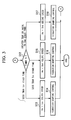
- step S1 it is determined whether an idling condition, from which it can be determined that the engine 11 is idling, is satisfied or not, by whether two conditions are satisfied or not by detection signals from the engine speed sensor 37 and the throttle opening sensor 39, the two conditions being a rotational speed condition in that the engine speed Ne is less than a predetermined value, and a valve opening condition in that the throttle valve opening TH is 0.
- step S1 In the case where it is determined in step S1 that at least one of the rotational speed condition and the valve opening condition is not satisfied, thus not satisfying the idling condition, a timer T1 is reset in step S2, and vibration damping control is inhibited in step S3. Hence power supply to the electric motor 12 from the power drive unit 16 is stopped, and the present control terminates.
- step S1 Conversely, in the case where it is determined that the rotational speed condition and the valve opening condition are both satisfied in step S1, thus satisfying the idling condition, flow proceeds toward vibration damping permission in steps 4 and 4'.
- the reason why flow proceeds toward vibration damping permission only when the idling condition is satisfied is that an engine is generally in a low rotational speed region when in an idling state, and occupants experience unpleasant vibrations. Furthermore, the reason why flow proceeds toward vibration damping inhibiting when the idling condition is not satisfied is that engine speed is comparatively high when not in an idling state, so there is less unpleasant vibration for the occupants, and it is desirable for engine power to not be consumed for vibration damping control but be used for driving.
- step S4 it is determined whether a power transmission system condition is satisfied or not by whether at least one of a clutch disengaged condition, being that the clutch is disengaged, or a neutral condition, being that the gear shift is in neutral, is satisfied or not, by detection signals from the clutch switch 43 and the neutral switch 44.
- a clutch disengaged condition being that the clutch is disengaged
- a neutral condition being that the gear shift is in neutral
- step S4' it is determined whether a power transmission system condition is satisfied or not by whether at least one of a drive disengaged condition, being that the gear shift is in P position or N position, or a brake on condition, being that the brake is on, is satisfied or not, by detection signals from the shift position sensor 42 and the brake switch 38.
- a drive disengaged condition being that the gear shift is in P position or N position
- a brake on condition being that the brake is on
- step S4 If the transmission 13 is a manual transmission, in the case where it is determined in step S4 that neither the clutch disengaged condition nor the neutral condition is satisfied, thus not satisfying the power transmission system condition, then in step S2 a timer T1 is reset, and in step S3 vibration damping control is inhibited. Hence power supply to the electric motor 12 from the power drive unit 16 is stopped, and the present control is terminated.
- step S4' if the transmission 13 is an automatic transmission, in the case where it is determined in step S4' that neither the drive disengaged condition nor the brake on condition is satisfied, thus not satisfying the power transmission system condition, then in step S2 the timer T1 is reset, and in step S3 vibration damping control is inhibited. Hence power supply to the electric motor 12 from the power drive unit 16 is stopped, and the present control is terminated.
- step S4 determines whether the transmission 13 is a manual transmission, in the case where it is determined in step S4 that at least one of the clutch disengaged condition and the neutral condition is satisfied, thus satisfying the power transmission system condition, flow proceeds toward vibration damping permission in step S5.
- step S4' determines whether the transmission 13 is an automatic transmission. If the transmission 13 is an automatic transmission, in the case where it is determined in step S4' that at least one of the drive disengaged condition and the brake on condition is satisfied, thus satisfying the power transmission system condition, flow proceeds toward vibration damping permission in step S5.
- step S5 it is determined whether an engine speed condition, being that the engine speed Ne is within a prescribed range where vibration damping is required, is satisfied or not, by a detection signal from the engine speed sensor 37. In the case where it is determined that the engine speed condition is not satisfied, then in step S2 the timer T1 is reset, and in step S3 vibration damping control is inhibited. Hence power supply to the electric motor 12 from the power drive unit 16 is stopped, and the present control is terminated.
- an engine speed condition being that the engine speed Ne is within a prescribed range where vibration damping is required
- step S5 determines whether the engine speed condition is satisfied.
- step S6 it is determined whether an engine negative pressure condition, being that the engine negative pressure PB is within a prescribed range, which when low can be used to determine that the engine load is low is satisfied or not, by a detection signal from the air intake passage pressure sensor 40.
- step S6 determines whether the engine negative pressure condition is satisfied. If it is determined in step S6 that the engine negative pressure condition is not satisfied, in step S2 the timer T1 is reset, and in step S3 vibration damping control is inhibited. Hence power supply to the electric motor 12 from the power drive unit 16 is stopped, and the present control is terminated.
- step S6 determines whether the engine negative pressure condition is satisfied.
- detection of the engine negative pressure PB is one means of determining the loading state of the engine.
- other sensors may be used to determine the engine load. In essence, it is sufficient to determine whether vibration damping control should be performed or not depending on the loading state of the engine.
- step S7 it is determined whether a vehicle speed condition, being that the vehicle speed V is less than a predetermined value that determines that the vehicle is stopped, is satisfied or not, by a detection signal from the vehicle speed sensor 36.
- step SA2 the timer T1 is reset, and in step SA3 vibration damping control is inhibited. Hence power supply to the electric motor 12 from the power drive unit 16 is stopped, and the present control is terminated.
- step S6 determines whether the vehicle condition is satisfied. If it is determined in step S6 that the vehicle condition is satisfied, flow proceeds toward vibration damping permission in step S8.
- the reason why flow proceeds toward vibration damping permission only when the vehicle speed V is less than a predetermined value is that in the case where the vehicle travels at such a speed as is determined to be not stopped, the vehicle is influenced by factors other than engine vibration, such as the roughness of the road surface and the like, and performing vibration damping control at this time only for the engine is meaningless.
- step S8 it is determined whether a water temperature condition, being that the engine water temperature TW is greater than a predetermined value that determines that the engine 11 is warm enough, is satisfied or not, by a detection signal from the water temperature sensor 41.
- step S7 the water temperature condition is not satisfied
- step S2 the timer T1 is reset, and in step S3 vibration damping control is inhibited. Hence power supply to the electric motor 12 from the power drive unit 16 is stopped, and the present control is terminated.
- step S8 determines whether the water temperature condition is satisfied.
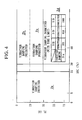
- step S9 it is determined whether a stored charge condition is satisfied or not, being that the stored charge SOC of the battery 17, which is monitored based on an output from the current sensor 24, is greater than a predetermined stored charge threshold (for example 25% in the case where the stored charge is falling, or 30% in the case where the stored charge is rising) that determines that it is sufficient for vibration damping control (refer to FIG. 4).
- a predetermined stored charge threshold for example 25% in the case where the stored charge is falling, or 30% in the case where the stored charge is rising
- step S9 In the case where it is determined in step S9 that the stored charge condition is not satisfied, then in step S2 the timer T1 is reset, and in step S3 vibration damping control is inhibited. Hence power supply to the electric motor 12 from the power drive unit 16 is stopped
- a generation torque limit is set to a predetermined upper limit (for example, 1.5kgfm), and the electric motor 12 may be controlled so as to charge the electric motor battery 17 via the power drive unit 16, such that the electric motor 12 generates electricity from the drive of the engine 11 within this torque limit.
- a predetermined upper limit for example, 1.5kgfm
- this shows regions (Za and Zb) where vibration damping control is inhibited, a region (Zc) where it is permitted, and furthermore a time limited permission region (Zd), based on only the stored charge SOC of the electric motor battery 17 monitored based on an output from the current sensor 24, and a current value EL, being a detection signal from the current sensor 22 installed on the 12 volt system auxiliary equipment 18.
- the horizontal axis represents the stored charge SOC of the battery 17, monitored based on an output from the current sensor 24, and the vertical axis represents current value EL, being a detection signal from the current sensor 22 installed on the 12 volt system auxiliary equipment 18.
- the stored charge SOC of the electric motor battery 17 takes priority. Firstly, when this stored charge SOC is less than or equal to a predetermined stored charge threshold, that is, there is little surplus of stored charge SOC, vibration damping is inhibited (Za), and conversely when it is greater than the predetermined stored charge threshold, that is, there is some surplus of stored charge SOC, vibration damping is permitted (Zc and Zd).
- unrestricted vibration damping control may be performed without a time limit, or vibration damping control may be performed with a time limit, depending on the current value EL, being a detection signal from the current sensor 22, in other words the motor-driven load state of the vehicle at the present time excepting the electric motor. That is to say, in the case where the current value EL is less than or equal to a predetermined EL (electrical load) threshold (for example, 35 amps), vibration damping is permitted with no condition (Zc), and in the case where the current value EL exceeds the EL threshold value, vibration damping is permitted with a time limit (Zd). Details will be described later.
- a predetermined EL (electrical load) threshold for example, 35 amps
- step S9 in the case where it is determined that the stored charge condition is satisfied, then the battery 17 is not charged, the electric motor 12 is controlled by the power drive unit 16 normally such that the detection signal from the current sensor 24 attached to the electric motor battery 17, in other words the current value, becomes 0, and flow proceeds toward vibration damping permission in step S10.
- the reason why vibration damping control is permitted only in the case where the stored charge SOC of the electric motor battery 17 is greater than the predetermined stored charge threshold value, is to avoid a case where performing vibration damping control makes the electric power produced by the engine insufficient, because vibration damping control using the electric motor requires a certain amount of energy, and hence in the case where the power deficiency is drawn from the electric motor battery, if there is no surplus in the electric motor battery the stored charge of the electric motor battery 17 is reduced, and in an extreme case there is a possibility that assistance cannot be given to the engine by the electric motor even if required.
- the reason why hysteresis is provided by setting two threshold values for the case where the stored charge is falling (25 percent in the case of this embodiment) and the case where the stored charge is rising (30 percent in the case of this embodiment), is to prevent control hunting.
- the stored charge SOC of the battery 17 is monitored directly in order to detect the stored charge of the electric motor battery 17.
- the stored charge of the battery 17 may be monitored by detecting the discharge rate of the battery.
- step S10 it is determined whether a 12 volt system consumption condition is satisfied or not, by a detection signal from the current sensor 22, being that a current value EL (electrical load of the vehicle except the electric motor) from the current sensor 22, indicating the amount of electricity consumed by the 12 volt system auxiliary equipment 18, is less than or equal to a predetermined electrical load threshold (for example, 35 amps) that determines that in the case where vibration damping control is performed by the electric motor 12, the current value EL is an amount such that electricity is drawn from the battery 17.
- a predetermined electrical load threshold for example, 35 amps
- step S10 vibration damping control can be performed without any problem at the battery 17 side, and with no time limit provided. Therefore, in step S11 power is supplied to the electric motor 12 by the power drive unit 16, vibration damping control is set to an active state, and the present control is terminated.
- step S10 determines whether the 12 volt system consumption condition is not satisfied.
- step S12 determines whether the 12 volt system consumption condition is not satisfied.
- step S18 the arrangement is such that vibration damping control is permitted but for a predetermined time limit, and also engine speed is increased as the elapsed time of vibration damping control increases. To be specific, this is described in the following steps S12 through step S18.
- step S12 the time of the timer T1 is determined.
- step S12 the time of the timer T1 is less than a predetermined first stage time (specifically shorter than 3 minutes) that determines that an idling state has just begun and so there is little influence on the stored charge SOC of the battery 17, then in step S13 the idling speed Ne of the engine 11 is set to a low predetermined fixed first idling speed (specifically 900rpm), by the injectors 32 and the air valve 34, and in step S14 power is supplied to the electric motor 12 from the power drive unit 16, vibration damping control is set to an active state, and the present control is terminated.
- a predetermined first stage time specifically shorter than 3 minutes
- step S15 the idling speed Ne of the engine 11 is set to a predetermined second idling speed (specifically 950rpm), which is higher than the first idling speed, by the injectors 32 and the air valve 34, and in step S16 power is supplied to the electric motor 12 from the power drive unit 16, vibration damping control is set to an active state, and the present control is terminated.
- a predetermined second stage time specifically shorter than 5 minutes
- step S12 the time of the timer T1 is greater than or equal to the predetermined second stage time (specifically greater than or equal to 5 minutes) that determines that the idling state has continued for a significantly long time and so there is a considerable influence on the stored charge SOC
- step S17 the idling speed Ne of the engine 11 is set to a predetermined third idling speed (specifically 1000rpm), which is higher than the second idling speed, by the injectors 32 and the air valve 34, and in step S18 vibration damping control is inhibited.
- a predetermined third idling speed specifically 1000rpm
- the reason why vibration damping is permitted unconditionally, with no time limit, in the case where the current value EL, being a signal detected from the current sensor 22, is less than or equal to the predetermined EL threshold, is that there is little possibility that the stored charge of the battery has decreased considerably because the current value EL is small, so the engine 11 can generate a sufficient electricity supply even if vibration damping control is performed, with a result that even if vibration damping control is performed for a long time, the amount of power drawn from the electric motor battery 17 is small.
- the reason why vibration damping is permitted with a time limit in the case where the current value EL, being a detection signal from the current sensor 22, exceeds the predetermined EL threshold, is that there is a possibility that the stored charge of the electric motor battery may reduce significantly if there is no time limit, because the electrical load of the vehicle at the present time is high, so if further vibration damping control is performed, then the amount of power drawn from the electric motor battery 17 will increase.
- the reason why the engine speed Ne is increased as the elapsed time of vibration damping control increases when vibration damping control is performed within a predetermined time limit (Zd), is that an increase in engine speed increases the electric power produced by the engine 11, thus reducing the amount of power drawn from the electric motor battery 17.
- the reason why the engine speed is increased in stages (900rpm ? 950rpm ? 1000rpm) as the elapsed time of vibration damping control increases as mentioned above, is that after a predetermined time (five minutes in this embodiment) has passed, if vibration damping control is suddenly discontinued while the engine speed is low, the unpleasant sensation experienced by occupants increases, but in the case where vibration damping control is discontinued in a state where the engine speed is increased in stages in this manner, there is a lower sensation of vibration and the occupants experience little unpleasantness.
- vibration damping control is inhibited (refer to Zb in the figure).
- this is a case where the air conditioner is disengaged, and the power transmission system is in a disengaged state, or the like, and so the electrical load of the vehicle is extremely small, and hence the load added to the engine 11 is small, so there is no need to perform vibration damping.
- vibration damping control is permitted with a time limit. In this manner, performing vibration damping control prevents an unrestricted large amount of power from being drawn continuously from the electric motor battery 17 in advance, so that the stored charge of the electric motor battery 17 can be maintained.
- FIG. 5 is a schematic diagram showing an overall structure of a parallel type hybrid vehicle of the second embodiment of a control apparatus of a hybrid vehicle of the present invention.
- An engine 11 is linked to a compressor 27 of an air conditioner, being auxiliary equipment, via a clutch 28.
- the compressor 27 is driven by the engine 11 when the clutch 28 is engaged by a control instruction from an ECU 15, and is disconnected from the drive of the engine 11 when the clutch is disengaged by a control instruction from the ECU 15.
- the drive torque to drive this compressor 27 is a mechanical load on the engine 11.
- a transmission 13 incorporates a clutch 30 for controlling the transmission of driving force from the engine 11 to the driving wheels under control instructions from the ECU 15.
- a clutch 30 for controlling the transmission of driving force from the engine 11 to the driving wheels under control instructions from the ECU 15.
- the D position of the transmission 13 is selected, even when idling the ECU 15 does not normally cut transmission of the driving force from the engine 11 to the driving wheels completely by this clutch 30, but induces so-called creeping torque.
- creeping torque of the drive transmission system is also a mechanical load on the engine 11.
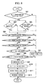
- the control content of the ECU 15 will be described with reference to the flow charts in FIG. 6 through FIG. 9.
- the ECU 15 performs vibration damping permission determination control of whether or not conditions are in a region where performing vibration damping control is permitted for suppressing vibration of the engine 11 by controlling power supplied to the electric motor 12, as follows (refer to FIG. 6 and FIG. 7).
- step SA1 it is determined whether an idling condition, from which it can be determined that the engine 11 is idling, is satisfied or not, by whether two conditions are satisfied or not by detection signals from the engine speed sensor 37 and the throttle opening sensor 39, the two conditions being a rotational speed condition in that the engine speed Ne is less than a predetermined value, and a valve opening condition in that the throttle valve opening TH is 0.
- step SA1 In the case where it is determined in step SA1 that at least one of the rotational speed condition and the valve opening condition is not satisfied, thus not satisfying the idling condition, a timer T1 is reset in step SA2, and vibration damping control is inhibited in step SA3. Hence power supply to the electric motor 12 from the power drive unit 16 is stopped, and the present control terminates.
- step S4 it is determined whether a transmission system condition is satisfied or not by whether at least one of a clutch disengaged condition, being that the clutch is disengaged, or a neutral condition, being that the gear shift is in neutral, is satisfied or not, by detection signals from the clutch switch 43 and the neutral switch 44.
- step SA4' it is determined whether a transmission system condition is satisfied or not by whether at least one of a drive disengaged condition, being that the gear shift is in P position or N position, and a brake on condition, being that the brake is on, is satisfied or not, by detection signals from the shift position sensor 42 and the brake switch 38.
- step SA4 If the transmission 13 is a manual transmission, in the case where it is determined in step SA4 that neither the clutch disengaged condition nor the neutral condition is satisfied, thus not satisfying the transmission system condition, then in step SA2 a timer T1 is reset, and in step SA3 vibration damping control is inhibited. Hence power supply to the electric motor 12 from the power drive unit 16 is stopped, and the present control is terminated.
- step SA4 the timer T1 is reset, and in step SA3 vibration damping control is inhibited. Hence power supply to the electric motor 12 from the power drive unit 16 is stopped, and the present control is terminated.
- step SA4 determines whether the transmission 13 is a manual transmission. If it is determined in step SA4 that at least one of the clutch disengaged condition and the neutral condition is satisfied, thus satisfying the transmission system condition, flow proceeds toward vibration damping permission in step SA5.
- step SA4' determines whether the transmission 13 is an automatic transmission. If the transmission 13 is an automatic transmission, in the case where it is determined in step SA4' that at least one of the drive disengaged condition and the brake on condition is satisfied, thus satisfying the transmission system condition, flow proceeds toward vibration damping permission in step S5.
- step S5 it is determined whether an engine negative pressure condition, being that the engine negative pressure PB, indicating the engine load, is less than a prescribed value which when low can be used to determine that the engine load is low, is satisfied or not, by a detection signal from the air intake passage pressure sensor 40.
- step SA5 the engine negative pressure condition is not satisfied
- step SA2 the timer T1 is reset, and in step SA3 vibration damping control is inhibited. Hence power supply to the electric motor 12 from the power drive unit 16 is stopped, and the present control is terminated.
- step S6 it is determined whether a vehicle speed condition, being that the vehicle speed V is less than a predetermined value that determines that the vehicle is stopped, is satisfied or not, by a detection signal from the vehicle speed sensor 36.
- step SA6 the vehicle condition is not satisfied
- step SA2 the timer T1 is reset, and in step SA3 vibration damping control is inhibited. Hence power supply to the electric motor 12 from the power drive unit 16 is stopped, and the present control is terminated.
- step SA7 it is determined whether a water temperature condition, being that the engine water temperature TW is greater than a predetermined value that determines that the engine 11 is warm enough, is satisfied or not, by a detection signal from the water temperature sensor 41.
- step SA7 the water temperature condition is not satisfied
- step SA2 the timer T1 is reset, and in step SA3 vibration damping control is inhibited. Hence power supply to the electric motor 12 from the power drive unit 16 is stopped, and the present control is terminated.
- step SA8 it is determined whether a stored charge condition is satisfied or not, being that the stored'charge SOC of the battery 17, which is monitored based on an output from the current sensor 24, is greater than a predetermined stored charge threshold (for example 25%) that determines that it is sufficient for vibration damping control.
- a stored charge condition for example 25%
- step SA9 the timer T1 is reset, and in step SA10 vibration damping control is inhibited. Hence power supply to the electric motor 12 from the power drive unit 16 is stopped.
- step SA11 a generation torque limit is set to a predetermined first upper limit (for example, 1.5kgfm), and the electric motor 12 is controlled so as to charge the electric motor battery 17 via the power drive unit 16, such that the electric motor 12 generates electricity from the drive of the engine 11 within this torque limit.
- the power drive unit 16 controls how much generation torque the electric motor 12 generates according to the characteristics shown in FIG. 10.
- the horizontal axis represents current value EL, being a detection signal from a current sensor 22 installed on a 12 volt system auxiliary equipment 18, and the vertical axis represents generation torque of the electric motor 12.
- Line a in FIG. 10 represents the electrical load by the 12 volt system auxiliary equipment 18, and line b in FIG. 10 represents a control line when the transmission 13 is an automatic transmission, a clutch 28 of an air conditioner is engaged, a compressor 27 is on, and a condition determined from a detection signal from a shift position sensor 42, where a clutch 30 is engaged but slipping, and creeping torque occurs on the driving side, in other words, that the gear shift is in D position.
- line c in FIG. 10 represents a control line when the transmission 13 is a manual transmission and the compressor 27 of the air conditioner is turned on, or when the transmission 13 is an automatic transmission, the compressor 27 of the air conditioner is turned on, and creeping torque occurs on the driving side.
- line d in FIG. 10 represents a control line when the transmission 13 is a manual transmission and the compressor 27 of the air conditioner is turned off, or when the transmission 13 is an automatic transmission, the compressor 27 of the air conditioner is turned off, and creeping torque does not occur on the driving side.
- control is performed according to these control lines, for example, in the case where the transmission 13 is an automatic transmission, the current value EL, being a detection signal from the current sensor 22, is 10 amps, and in a situation where the compressor 27 is on and creeping torque occurs, that is, in a situation where the mechanical load on the engine 11 is high, the electric motor 12 is controlled by the power drive unit 16 such that the generation torque of the electric motor 12 is reduced according to the control line b. Furthermore, when the compressor 27 is on, or when creeping torque occurs, that is, in a situation where the mechanical load on the engine 11 is low, the electric motor 12 is controlled by the power drive unit 16 such that the generation torque of the electric motor 12 is increased higher than the above described value according to the control line c.
- the electric motor 12 is controlled by the power drive unit 16 such that the generation torque of the electric motor 12 is increased higher than the above described value according to the control line d.
- step SA8 in the case where it is determined that the stored charge condition is satisfied, then the battery 17 is not charged, and hence the electric motor 12 is controlled by the power drive unit 16 normally such that the detection signal from the current sensor 24 attached to the battery 17, in other words the current value, becomes 0.
- step SA13 it is determined whether a 12 volt system consumption condition is satisfied or not, by a detection signal from the current sensor 22, being that a current value EL from the current sensor 22, indicating the amount of electricity consumed by the 12 volt system auxiliary equipment 18, is less than or equal to a predetermined value (for example, 35 amps) that determines that in the case where vibration damping control is performed by the electric motor 12, the current value EL is an amount such that electricity is drawn from the battery 17.
- a predetermined value for example, 35 amps
- step SA14 power is supplied to the electric motor 12 by the power drive unit 16, vibration damping control is set to an active state, and the present control is terminated.
- step SA15 the time of the timer T1 is determined.
- step SA15 the time of the timer T1 is less than a predetermined first stage time (specifically shorter than 3 minutes) that determines that an idling state has just begun and so there is little influence on the stored charge SOC of the battery 17, then in step SA16 the idling speed Ne of the engine 11 is set to a low predetermined fixed first idling speed (specifically 900rpm), by the injectors 32 and the air valve 34, and in step SA17 power is supplied to the electric motor 12 from the power drive unit 16, vibration damping control is set to an active state, and the present control is terminated.
- a predetermined first stage time specifically shorter than 3 minutes
- step SA15 the time of the timer T1 is less than a predetermined second stage time (specifically shorter than 5 minutes) that determines that the idling state has continued for a long time and so there is some influence on the stored charge SOC
- step SA18 the idling speed Ne of the engine 11 is set to a predetermined second idling speed (specifically 950rpm), which is higher than the first idling speed, by the injectors 32 and the air valve 34, and in step SA19 power is supplied to the electric motor 12 from the power drive unit 16, vibration damping control is set to an active state, and the present control is terminated.
- a predetermined second stage time specifically shorter than 5 minutes
- step SA15 the time of the timer T1 is greater than or equal to the predetermined second stage time (specifically greater than or equal to 5 minutes) that determines that the idling state has continued for a considerably long time and so there is a considerable influence on the stored charge SOC
- step SA20 the idling speed Ne of the engine 11 is set to a predetermined third idling speed (specifically 1000rpm), which is higher than the second idling speed, by the injectors 32 and the air valve 34, and in step SA21 vibration damping control is inhibited.
- a predetermined third idling speed specifically 1000rpm
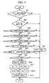
- the ECU 15 further controls the following first mechanical load control, concurrently with the vibration damping permission determination control (refer to FIG. 8).
- step SB1 it is determined whether an idling condition, from which it can be determined that the engine 11 is idling, is satisfied or not, by whether two conditions are satisfied or not by detection signals from the engine speed sensor 37 and the throttle opening sensor 39, the two conditions being a rotational speed condition in that the engine speed Ne is less than a predetermined value, and a valve opening condition in that the throttle valve opening TH is 0.
- step SB1 In the case where it is determined in step SB1 that at least one of the rotational speed condition and the valve opening condition is not satisfied, thus not satisfying the idling condition, a timer T1 is reset in step SB2, and the present control terminates.
- step SB3 it is determined whether a transmission system condition is satisfied or not by whether at least one of a clutch disengaged condition, being that the clutch is disengaged, and a neutral condition, being that the gear shift is in neutral is satisfied, by detection signals from the clutch switch 43 and the neutral switch 44.
- step SB3' it is determined whether a transmission system condition is satisfied or not by whether at least one of a drive disengaged condition, being that the gear shift is in P position or N position, and a brake on condition, being that the brake is on is satisfied, by detection signals from the shift position sensor 42 and the brake switch 38.
- step SB3 If the transmission 13 is a manual transmission, in the case where it is determined in step SB3 that neither the clutch disengaged condition nor the neutral condition is satisfied, thus not satisfying the transmission system condition, then in step SB2 a timer T1 is reset, and the present control is terminated.
- step SB2 the timer T2 is reset, and the present control is terminated.
- step SB3 determines whether the transmission 13 is a manual transmission. If it is determined in step SB3 that at least one of the clutch disengaged condition and the neutral condition is satisfied, thus satisfying the transmission system condition, flow proceeds to step SB4.
- step SB3 determines whether the transmission 13 is an automatic transmission. If the transmission 13 is an automatic transmission, in the case where it is determined in step SB3' that at least one of the drive disengaged condition and the brake on condition is satisfied, thus satisfying the transmission system condition, flow proceeds to step SB4.
- step SB4 it is determined whether an engine negative pressure condition, being that the engine negative pressure PB, indicating the engine load, is less than a prescribed value which when low can be used to determine that the engine load is low, is satisfied or not, by a detection signal from the air intake passage pressure sensor 40.
- step SB4 the timer T2 is reset, and the present control is terminated.
- step SB5 it is determined whether a vehicle speed condition, being that the vehicle speed V is less than a predetermined value that determines that the vehicle is stopped, is satisfied or not, by a detection signal from the vehicle speed sensor 36.
- step SB2 the timer T2 is reset, and the present control is terminated.
- step SB6 it is determined whether a water temperature condition, being that the engine water temperature TW is greater than a predetermined value that determines that the engine 11 is warm enough, is satisfied or not, by a detection signal from the water temperature sensor 41.
- step SB6 the timer T2 is reset, and the present control is terminated.
- step SB7 it is determined whether a stored charge condition is satisfied or not, being that the stored charge SOC of the battery 17, which is monitored based on an output from the current sensor 24, is below a predetermined second threshold (lower value than the first threshold, for example 25%) that determines whether it subsequently has an influence on assistance control of the engine 11 by the electric motor 12.
- a predetermined second threshold lower value than the first threshold, for example 25%
- step SB7 the timer T2 is reset in step SB2, and the present control is terminated.
- step SB8 it is determined in step SB8 whether the time of the timer T2, from when the stored charge SOC of the battery 17 dropped below the second threshold, is greater or not than a predetermined value for determining whether this drop is temporary.
- step SB8 the present control is terminated.
- step SB9 the clutch 28 for the compressor 27 of the air conditioner is disengaged, the compressor is disconnected from the engine 11, and the drive torque, that is the mechanical load, is reduced.
- the injectors 32 and the air valve 34 are controlled to increase the idling speed Ne of the engine 11 to a predetermined fourth idling speed (greater than the abovementioned third idling speed (specifically 1100rpm)) that determines that sufficient generation torque can be obtained.
- step SB11 when the electric motor 12 generates electricity from the drive of the engine 11, the generation torque limit is set to a predetermined second upper limit wherein an allowance for a mechanical load that is required to drive the compressor 27 is added to the abovementioned first upper limit (for example 1.8kgfm), and in step SB12 the charging of the electric motor 12 is controlled by the power drive unit 16, such that the electric motor 12 generates electricity from the drive of the engine 11 within a range where the generation torque does not exceed this second upper limit.
- a predetermined second upper limit wherein an allowance for a mechanical load that is required to drive the compressor 27 is added to the abovementioned first upper limit (for example 1.8kgfm)
- the charging of the electric motor 12 is controlled by the power drive unit 16, such that the electric motor 12 generates electricity from the drive of the engine 11 within a range where the generation torque does not exceed this second upper limit.
- the ECU 15 further performs the following second mechanical load control, concurrently with the vibration damping permission determination control and first mechanical load control, provided the transmission 13 is an automatic transmission (refer to FIG. 9).
- step SC1 it is determined whether an idling condition, from which it can be determined that the engine 11 is idling, is satisfied or not, by whether two conditions are satisfied or not by detection signals from the engine speed sensor 37 and the throttle opening sensor 39, the two conditions being a rotational speed condition in that the engine speed Ne is less than a predetermined value, and a valve opening condition in that the throttle valve opening TH is 0.
- step SC1 determines that at least one of the rotational speed condition and the valve opening condition is not satisfied, thus not satisfying the idling condition.
- step SC3 it is determined whether a transmission system condition is satisfied or not by whether at least one of a drive disengaged condition, being that the gear shift is in P position or N position, and a brake on condition, being that the brake is on is satisfied, by detection signals from the shift position sensor 42 and the brake switch 38.
- step SC2 the timer T3 is reset, and the present control is terminated.
- step SC3' determines whether at least one of the drive disengaged condition and the brake on condition is satisfied, thus satisfying the transmission system condition.
- step SC4 it is determined whether an engine negative pressure condition, being that the engine negative pressure PB, indicating the engine load, is within a prescribed value which when low can be used to determine that the engine load is low, is satisfied or not, by a detection signal from the air intake passage pressure sensor 40.
- step SC4 the timer T3 is reset, and the present control is terminated.
- step SC5 it is determined whether a vehicle speed condition, being that the vehicle speed V is less than a predetermined value that determines that the vehicle is stopped, is satisfied or not, by a detection signal from the vehicle speed sensor 36.
- step SC2 the timer T3 is reset, and the present control is terminated.
- step SC6 it is determined whether a water temperature condition, being that the engine water temperature TW is greater than a predetermined value that determines that the engine 11 is warm enough, is satisfied or not, by a detection signal from the water temperature sensor 41.
- step SC6 the timer T2 is reset, and the present control is terminated.
- step SC7 it is determined whether a stored charge condition is satisfied or not, being that the stored charge SOC of the battery 17, which is monitored based on an output from the current sensor 24, is below a predetermined second threshold (lower value than the first threshold, for example 25%) that determines whether it subsequently has an influence on assistance control of the engine 11 by the electric motor 12.
- a predetermined second threshold lower value than the first threshold, for example 25%
- step SC7 the timer T2 is reset in step SC2, and the present control is terminated.
- step SC8 it is determined in step SC8 whether the time of the timer T3, from when the stored charge SOC of the battery 17 dropped below the second threshold, is greater or not than a predetermined value for determining whether this drop is temporary.
- step SC8 the present control is terminated.
- step SC9 it is determined by a detection signal from the shift position sensor 42 of the transmission 13 whether it is in a situation where creeping torque occurs or not, in other words, whether or not the gear shift is in D position rather than P position or N position.
- step SC9 the present control is terminated.
- step SC10 the clutch 30 of the transmission 13 is disengaged, the engine 11 is disconnected from the drive transmission system, creeping torque is set to 0, and the mechanical load on the engine 11 is reduced.
- the injectors 32 and the air valve 34 are controlled to increase the idling speed Ne of the engine 11 to a predetermined fourth idling speed (greater than the abovementioned third idling speed (specifically 1100rpm)) that determines that sufficient generation torque can be obtained.
- step SC12 when the electric motor 12 generates electricity from the drive of the engine 11, the generation torque limit is set to a predetermined second upper limit wherein an allowance for generation of the creeping torque is added to the abovementioned first upper limit (for example 1.8kgfm), and in step SC13 the charging of the electric motor 12 is controlled by the power drive unit 16, such that the electric motor 12 generates electricity from the drive of the engine 11 within a range where the generation torque does not exceed this second upper limit.
- a predetermined second upper limit wherein an allowance for generation of the creeping torque is added to the abovementioned first upper limit (for example 1.8kgfm)
- the charging of the electric motor 12 is controlled by the power drive unit 16, such that the electric motor 12 generates electricity from the drive of the engine 11 within a range where the generation torque does not exceed this second upper limit.
- a control apparatus for a hybrid vehicle that has: an engine 11 which outputs a propulsion force for a vehicle; an electric motor 12 which assists the output from the engine; and a battery 17 for storing electric power generated by the electric motor, and further monitors the stored charge of the battery 17 by a current sensor 24 and an ECU 15, when the engine 11 is idling (step SA1), when the stored charge SOC of the battery 17 detected by the current sensor 24 and the ECU 15 is greater than a predetermined first threshold (step SA8), vibration damping control for suppressing vibration of the engine 11 is performed by the electric motor 12 (step SA14).
- step SA8 vibration damping control by the electric motor 12
- step SA10 the stored charge of the battery 17 is less than or equal to the first threshold
- step SA10 vibration damping control by the electric motor 12
- step SA10 the stored charge SOC of the battery 17 detected by the current sensor 24 and the ECU 15 is below a predetermined second threshold that is lower than the first threshold
- step SB10 and SC11 the idling speed Ne of the engine 11 is increased (steps SB10 and SC11).
- step SB7 and SC7 when the stored charge SOC of the battery 17 detected by the current sensor 24 and the ECU 15 is below the second threshold (steps SB7 and SC7), since the drive torque of the compressor 27 of the air conditioner and creeping torque, being mechanical loads other than the drive torque of the electric motor 12 driven by the engine 11, are removed from the drive torque of the engine 11 (steps SB9 and SC10), it is possible to further increase the torque that can be distributed as generation torque for the electric motor 12 to generate electricity.
- the arrangement may be such that the threshold of when mechanical loads other than the drive torque of the electric motor 12 are removed from the drive torque of the engine 11 is set to a third threshold (for example 5%) that is lower than the abovementioned second threshold, and if the stored charge SOC of the battery 17 detected by the current sensor 24 and the ECU 15 is below this third threshold, the mechanical loads, other than the drive torque of the electric motor 12 driven by the engine, are removed from the drive torque.
- a third threshold for example 5%
- the arrangement may be such that at least one of the drive torque of the air conditioner compressor 27 and the creeping torque is removed from the drive torque of the engine 11.
- the control apparatus of a hybrid vehicle according to the first aspect of the invention, only in the case where the stored charge of an electric motor battery is greater than a predetermined stored charge threshold, that is, only in the case where there is some surplus stored charge in the electric motor battery, is vibration damping control performed by a vibration damping device. Therefore it is possible to prevent in advance a situation in which there is no surplus stored charge of the electric motor battery, leading to the stored charge of the electric motor battery being reduced significantly by the operation of the vibration damping control device, and thus it is possible to prevent the stored charge of the electric motor battery falling too low.
- the control apparatus for a hybrid vehicle it is possible to perform vibration damping control in a state where there is some surplus stored charge in the electric motor battery, the vehicle is idling, and the engine rotation is stable in regard to the engine speed and engine load, but excepting a case where a high load is required on the engine, that is, only when vibration damping control is genuinely required. Therefore, it is possible to prevent in advance a situation where power is drawn from the electric motor battery wastefully by performing vibration damping control when there is little requirement.
- the control apparatus for a hybrid vehicle in the case where the electrical load of the vehicle in its existing state is high, and vibration damping control is being performed, then in the case where the electric power produced by the engine is insufficient and the deficiency must be drawn from the electric motor battery, by performing vibration damping control only for a predetermined limited time, it is possible to prevent in advance a situation in which the stored charge of the electric motor battery is reduced due to performing vibration damping control over a long time.
- the control apparatus for a hybrid vehicle by increasing the engine speed, the amount of electric power produced by the engine increases, and the amount of electric power drawn from the electric motor battery decreases. As a result, it is possible to minimize the decrease of the stored charge of the electric motor battery, and additionally, the increase in the engine speed can reduce the vibration that occupants experience.
- the control apparatus for a hybrid vehicle when the stored charge of the battery detected by the storage state monitoring device is less than or equal to the predetermined stored charge threshold, vibration damping control by the electric motor is stopped, and thus first of all power consumption is suppressed.
- the stored charge of the battery still decreases, and when the stored charge of the battery detected by the storage state monitoring device is less than the predetermined second threshold that is lower than the stored charge threshold, the idling speed of the engine is increased, and the drive torque of the engine is increased.
- the control apparatus for a hybrid vehicle when the stored charge of the battery detected by the storage state monitoring device is the same as the second threshold or less than a third threshold that is even lower, if the arrangement is such that mechanical loads, other than the drive torque of the electric motor driven by the engine, are removed from the drive torque, it is possible to further increase the torque that can be distributed as generation torque for the electric motor to generate electricity.
- a mechanical load is either drive torque of an air conditioner compressor or creeping torque, since the torques required for these drives are large it is possible to effectively increase the torque that can be distributed as generation torque for the electric motor to generate electricity.
Landscapes
- Engineering & Computer Science (AREA)
- Mechanical Engineering (AREA)
- Combustion & Propulsion (AREA)
- Chemical & Material Sciences (AREA)
- Transportation (AREA)
- Power Engineering (AREA)
- General Engineering & Computer Science (AREA)
- Automation & Control Theory (AREA)
- Life Sciences & Earth Sciences (AREA)
- Sustainable Development (AREA)
- Sustainable Energy (AREA)
- Hybrid Electric Vehicles (AREA)
- Electric Propulsion And Braking For Vehicles (AREA)
- Control Of Vehicle Engines Or Engines For Specific Uses (AREA)
Applications Claiming Priority (5)
| Application Number | Priority Date | Filing Date | Title |
|---|---|---|---|
| JP22313399 | 1999-08-05 | ||
| JP22313499 | 1999-08-05 | ||
| JP22313499A JP3248891B2 (ja) | 1999-08-05 | 1999-08-05 | ハイブリッド車両の制御装置 |
| JP22313399A JP3340405B2 (ja) | 1999-08-05 | 1999-08-05 | ハイブリッド車両の制御装置 |
| PCT/JP2000/005246 WO2001010666A1 (en) | 1999-08-05 | 2000-08-04 | Control device of hybrid vehicle |
Publications (3)
| Publication Number | Publication Date |
|---|---|
| EP1221394A1 true EP1221394A1 (de) | 2002-07-10 |
| EP1221394A4 EP1221394A4 (de) | 2003-10-01 |
| EP1221394B1 EP1221394B1 (de) | 2005-10-26 |
Family
ID=26525291
Family Applications (1)
| Application Number | Title | Priority Date | Filing Date |
|---|---|---|---|
| EP00951884A Expired - Lifetime EP1221394B1 (de) | 1999-08-05 | 2000-08-04 | Regel vorrichtung fur ein hybrid fahrzeug |
Country Status (8)
| Country | Link |
|---|---|
| US (1) | US6621244B1 (de) |
| EP (1) | EP1221394B1 (de) |
| KR (1) | KR100455854B1 (de) |
| CN (1) | CN1278883C (de) |
| AU (1) | AU760387B2 (de) |
| CA (1) | CA2378354C (de) |
| DE (1) | DE60023535T2 (de) |
| WO (1) | WO2001010666A1 (de) |
Cited By (13)
| Publication number | Priority date | Publication date | Assignee | Title |
|---|---|---|---|---|
| WO2004026606A1 (de) * | 2002-09-05 | 2004-04-01 | Robert Bosch Gmbh | Kraftfahrzeug mit einem hybridantrieb sowie verfahren zur leerlaufregelung eines hybridantriebs eines kraftfahrzeugs |
| EP1433641A1 (de) * | 2002-12-26 | 2004-06-30 | HONDA MOTOR CO., Ltd. | Antriebssteuervorrichtung für Hybridfahrzeug |
| FR2858018A1 (fr) * | 2003-07-23 | 2005-01-28 | Renault Sa | Groupe motopropulseur hybride et procede de commande de ralenti |
| FR2908476A1 (fr) * | 2006-11-13 | 2008-05-16 | Mitsubishi Electric Corp | Dispositif de commande pour moteur a combustion interne |
| US7785539B2 (en) * | 2003-04-04 | 2010-08-31 | Texaco Inc. | Method of controlling a hydrogen generator |
| EP2036794A3 (de) * | 2007-09-17 | 2010-09-01 | Denso Corporation | Fahrzeugsteuersystem und -verfahren |
| WO2011004228A3 (en) * | 2009-07-09 | 2011-05-12 | Toyota Jidosha Kabushiki Kaisha | Vehicular damping control system |
| WO2010131091A3 (en) * | 2009-05-13 | 2011-05-12 | Toyota Jidosha Kabushiki Kaisha | Sprung mass damping control system of vehicle |
| WO2014064365A1 (fr) * | 2012-10-25 | 2014-05-01 | Technoboost | Procede de filtration des vibrations d'un moteur de vehicule hybride comportant une machine hydraulique |
| DE102007027165B4 (de) * | 2006-06-16 | 2014-05-22 | GM Global Technology Operations LLC (n. d. Ges. d. Staates Delaware) | Steuersystem und Verfahren zum Steuern einer Elektromaschine eines Hybridfahrzeugs zum Verringern von Kaltklappern |
| EP2653363A4 (de) * | 2010-12-17 | 2015-09-23 | Aisin Ai Co Ltd | Kraftübertragungssteuerungsvorrichtung für ein fahrzeug |
| WO2018108467A1 (de) * | 2016-12-15 | 2018-06-21 | Audi Ag | Verfahren und vorrichtung zum einstellen einer leerlaufdrehzahl einer verbrennungskraftmaschine eines kraftfahrzeugs sowie kraftfahrzeug |
| FR3079802A1 (fr) * | 2018-04-09 | 2019-10-11 | Psa Automobiles Sa | Systeme de commande pour vehicule hybride |
Families Citing this family (53)
| Publication number | Priority date | Publication date | Assignee | Title |
|---|---|---|---|---|
| JP3810654B2 (ja) * | 2001-06-11 | 2006-08-16 | 本田技研工業株式会社 | ハイブリッド車両の制御装置 |
| DE10162017A1 (de) * | 2001-12-18 | 2003-07-10 | Bosch Gmbh Robert | Vorrichtung und Verfahren zur Regelung der Fahrgeschwindigkeit eines Fahrzeugs |
| JP3568941B2 (ja) * | 2002-06-19 | 2004-09-22 | 本田技研工業株式会社 | ハイブリッド車両の制御装置 |
| JP3466600B1 (ja) * | 2002-07-16 | 2003-11-10 | 本田技研工業株式会社 | ハイブリッド車両の制御装置 |
| JP3958220B2 (ja) * | 2003-01-16 | 2007-08-15 | 株式会社豊田中央研究所 | トルク伝達装置 |
| JP4596381B2 (ja) * | 2004-02-02 | 2010-12-08 | アイシン・エィ・ダブリュ株式会社 | 電動車両駆動制御装置及び電動車両駆動制御方法 |
| JP4385821B2 (ja) * | 2004-03-30 | 2009-12-16 | トヨタ自動車株式会社 | 車両搭載作動装置の制御装置および波動強度特性取得装置 |
| DE102005034794A1 (de) * | 2004-07-23 | 2006-02-23 | Ford Global Technologies, LLC, Dearborn | Verfahren zum Dämpfen von Vibrationen im Antriebsstrang eines hybridelektrischen Fahrzeugs |
| US7100362B2 (en) * | 2004-07-30 | 2006-09-05 | Ford Global Technologies, Llc | Vehicle and method for operating a vehicle to reduce exhaust emissions |
| DE102005018437A1 (de) * | 2005-04-21 | 2006-10-26 | Robert Bosch Gmbh | Verfahren zum Betreiben eines Fahrzeug-Antriebs und Vorrichtung zur Durchführung des Verfahrens |
| CN1907747B (zh) * | 2005-08-01 | 2010-11-10 | 爱信艾达株式会社 | 电动车辆驱动控制装置及电动车辆驱动控制方法 |
| JP2007064209A (ja) * | 2005-08-05 | 2007-03-15 | Fujitsu Ten Ltd | エンジン制御装置、制御方法、及び制御システム |
| JP4592543B2 (ja) * | 2005-09-15 | 2010-12-01 | 川崎重工業株式会社 | 自動二輪車 |
| JP4174061B2 (ja) * | 2006-03-23 | 2008-10-29 | 本田技研工業株式会社 | ハイブリッド車両の能動型制振制御装置 |
| US7292932B1 (en) | 2006-11-13 | 2007-11-06 | Ford Global Technologies, Llc | System and method for controlling speed of an engine |
| JP4396717B2 (ja) * | 2007-03-07 | 2010-01-13 | トヨタ自動車株式会社 | 車両の制御装置、制御方法、その方法を実現させるプログラムおよびそのプログラムを記録した記録媒体 |
| US7766109B2 (en) * | 2007-09-28 | 2010-08-03 | Gm Global Technology Operations, Inc. | Hybrid powertrains and methods of operating |
| JP5018452B2 (ja) * | 2007-12-18 | 2012-09-05 | トヨタ自動車株式会社 | 車両用動力伝達装置の制御装置 |
| CN102421633B (zh) * | 2009-05-13 | 2015-08-12 | 丰田自动车株式会社 | 减振控制装置 |
| JP5477030B2 (ja) * | 2009-05-22 | 2014-04-23 | 日産自動車株式会社 | 電動車両の制御装置 |
| US8825291B2 (en) * | 2009-10-05 | 2014-09-02 | Toyota Jidosha Kabushiki Kaisha | Vehicle vibration-damping controlling apparatus |
| JP5565627B2 (ja) * | 2010-09-29 | 2014-08-06 | アイシン・エィ・ダブリュ株式会社 | 制御装置 |
| WO2012047226A2 (en) * | 2010-10-08 | 2012-04-12 | International Truck Intellectual Property Company, Llc | Supervisory control system for series type hybrid-electric powertrains |
| US8651209B2 (en) * | 2010-12-20 | 2014-02-18 | Sony Corporation | Kinetic energy storage systems and methods of use |
| CN103298637B (zh) * | 2011-02-08 | 2016-03-30 | 本田技研工业株式会社 | 混合动力车辆的驱动装置 |
| EP2736760A4 (de) | 2011-07-26 | 2015-11-04 | Gogoro Inc | Dynamisch begrenzung eines fahrzeugbetriebs für möglichst ökonomische nutzung |
| WO2013016570A1 (en) | 2011-07-26 | 2013-01-31 | Gogoro, Inc. | Apparatus, method and article for authentication, security and control of power storage devices, such as batteries, based on user profiles |
| JP6096773B2 (ja) | 2011-07-26 | 2017-03-15 | ゴゴロ インク | 電池などの電力貯蔵装置の認証、セキュリティ、及び制御用の装置、方法、及び物品 |
| US9552682B2 (en) | 2011-07-26 | 2017-01-24 | Gogoro Inc. | Apparatus, method and article for redistributing power storage devices, such as batteries, between collection, charging and distribution machines |
| ES2692524T3 (es) | 2011-07-26 | 2018-12-04 | Gogoro Inc. | Aparato, método y artículo para proporcionar datos de diagnóstico de vehículo |
| WO2013052785A1 (en) * | 2011-10-05 | 2013-04-11 | Gogoro, Inc. | Detectible indication of an electric motor vehicle standby mode |
| CN111216680B (zh) | 2011-11-08 | 2021-09-10 | 睿能创意公司 | 用于车辆安全的装置、方法及物品 |
| DE102012209753B4 (de) * | 2012-06-12 | 2026-02-19 | Robert Bosch Gmbh | Dämpfungsschaltung für eine Energiespeichereinrichtung und Verfahren zum Dämpfen von Schwingungen des Ausgangsstroms einer Energiespeichereinrichtung |
| WO2014078557A1 (en) | 2012-11-16 | 2014-05-22 | Gogoro, Inc. | Apparatus, method and article for vehicle turn signals |
| CN104325911A (zh) * | 2013-07-22 | 2015-02-04 | 北汽福田汽车股份有限公司 | 汽车的座椅加热控制方法、系统及汽车 |
| JP6201210B2 (ja) * | 2013-09-24 | 2017-09-27 | 日立オートモティブシステムズ株式会社 | 電動車両の制御装置及び電動車両の制御方法 |
| TWI603552B (zh) | 2014-08-11 | 2017-10-21 | 睿能創意公司 | 多方向性的電連接器、插頭及系統 |
| KR101588781B1 (ko) * | 2014-10-21 | 2016-01-26 | 현대자동차 주식회사 | 차량의 발전모드 제어방법 |
| US9758052B2 (en) * | 2014-11-13 | 2017-09-12 | Ford Global Technologies, Llc | Power spike mitigation |
| ES2934213T3 (es) | 2015-06-05 | 2023-02-20 | Gogoro Inc | Sistemas y métodos para detección de carga de vehículo y respuesta |
| KR101755501B1 (ko) | 2015-12-10 | 2017-07-07 | 현대자동차 주식회사 | 하이브리드 차량의 능동 진동 제어 방법 및 장치 |
| KR101713759B1 (ko) | 2015-12-10 | 2017-03-08 | 현대자동차 주식회사 | 하이브리드 차량의 능동 진동 제어 방법 및 장치 |
| US10454144B2 (en) * | 2016-05-17 | 2019-10-22 | Ford Global Technologies, Llc | System and method for acoustic determination of battery cell expansion |
| CN107630758B (zh) * | 2016-07-18 | 2020-05-01 | 上海汽车集团股份有限公司 | 发动机怠速转速的控制方法及控制装置 |
| US10059328B2 (en) * | 2016-08-11 | 2018-08-28 | Ford Global Technologies, Llc | System and method to control battery current during rolling stop-start events |
| US9850838B1 (en) | 2016-10-03 | 2017-12-26 | Toyota Motor Engineering & Manufacturing North America, Inc. | Engine shock dampening system |
| KR101855774B1 (ko) * | 2016-12-13 | 2018-06-20 | 현대자동차 주식회사 | 하이브리드 차량의 진동 제어 장치 및 방법 |
| KR101855789B1 (ko) * | 2016-12-13 | 2018-06-20 | 현대자동차 주식회사 | 하이브리드 차량의 진동 제어 장치 및 방법 |
| KR102383236B1 (ko) * | 2016-12-13 | 2022-04-05 | 현대자동차 주식회사 | 하이브리드 차량의 진동 제어 장치 및 방법 |
| JP2021155005A (ja) * | 2020-03-30 | 2021-10-07 | 株式会社豊田自動織機 | ハイブリッド車両 |
| CN114776454B (zh) * | 2021-06-29 | 2024-09-10 | 长城汽车股份有限公司 | 发动机控制方法、装置、车辆、存储介质及设备 |
| CN115158283B (zh) * | 2022-07-06 | 2024-08-27 | 东风汽车集团股份有限公司 | 混合动力系统换挡控制方法及装置 |
| JP7740214B2 (ja) | 2022-11-29 | 2025-09-17 | トヨタ自動車株式会社 | ハイブリッド車両の充電制御装置 |
Family Cites Families (15)
| Publication number | Priority date | Publication date | Assignee | Title |
|---|---|---|---|---|
| JPS59122754A (ja) | 1982-12-29 | 1984-07-16 | Mazda Motor Corp | エンジンのトルク変動抑制装置 |
| JPS6170149A (ja) | 1984-09-12 | 1986-04-10 | Japan Electronic Control Syst Co Ltd | 内燃機関のアイドル回転数制御装置 |
| JPS61135936A (ja) | 1984-12-04 | 1986-06-23 | Nissan Motor Co Ltd | 内燃機関のトルク変動低減装置 |
| JP2950880B2 (ja) * | 1990-02-01 | 1999-09-20 | 株式会社日立製作所 | 車体振動低減制御装置 |
| JP3387511B2 (ja) | 1991-03-27 | 2003-03-17 | 株式会社日立製作所 | 回転0.5次振動低減装置 |
| JPH05302525A (ja) | 1992-04-24 | 1993-11-16 | Nippondenso Co Ltd | エンジンの回転速度変動抑制装置 |
| JP3613801B2 (ja) * | 1992-09-29 | 2005-01-26 | マツダ株式会社 | 車両の振動低減装置 |
| JP3314484B2 (ja) * | 1992-12-28 | 2002-08-12 | 株式会社デンソー | 車両制振装置 |
| JP3375010B2 (ja) | 1993-09-02 | 2003-02-10 | 株式会社デンソー | 内燃機関用発電電動機の制御装置 |
| JPH08289407A (ja) * | 1995-02-13 | 1996-11-01 | Nippon Soken Inc | ハイブリッド車の発電制御装置 |
| JP4148540B2 (ja) | 1996-03-14 | 2008-09-10 | 株式会社三共 | 遊技機 |
| JP3230798B2 (ja) | 1996-07-03 | 2001-11-19 | 沖電気工業株式会社 | 冗長システム |
| DE19721298C2 (de) * | 1997-05-21 | 2001-09-06 | Mannesmann Sachs Ag | Hybrid-Fahrantrieb für ein Kraftfahrzeug |
| DE19833154C2 (de) * | 1998-07-23 | 2000-08-10 | Mak System Gmbh | Gleiskettenfahrzeug |
| US6176808B1 (en) * | 1999-07-15 | 2001-01-23 | Ford Global Technologies, Inc. | Hybrid vehicle powertrain and control therefor |
-
2000
- 2000-08-04 CA CA002378354A patent/CA2378354C/en not_active Expired - Fee Related
- 2000-08-04 AU AU64720/00A patent/AU760387B2/en not_active Ceased
- 2000-08-04 WO PCT/JP2000/005246 patent/WO2001010666A1/ja not_active Ceased
- 2000-08-04 CN CNB008112711A patent/CN1278883C/zh not_active Expired - Fee Related
- 2000-08-04 KR KR10-2002-7001428A patent/KR100455854B1/ko not_active Expired - Fee Related
- 2000-08-04 US US10/048,448 patent/US6621244B1/en not_active Expired - Lifetime
- 2000-08-04 DE DE60023535T patent/DE60023535T2/de not_active Expired - Fee Related
- 2000-08-04 EP EP00951884A patent/EP1221394B1/de not_active Expired - Lifetime
Cited By (25)
| Publication number | Priority date | Publication date | Assignee | Title |
|---|---|---|---|---|
| US7971665B2 (en) | 2002-09-05 | 2011-07-05 | Robert Bosch Gmbh | Motor vehicle comprising a hybrid drive and method for controlling the idle speed of a hybrid drive of a motor vehicle |
| WO2004026606A1 (de) * | 2002-09-05 | 2004-04-01 | Robert Bosch Gmbh | Kraftfahrzeug mit einem hybridantrieb sowie verfahren zur leerlaufregelung eines hybridantriebs eines kraftfahrzeugs |
| US7040433B2 (en) | 2002-12-26 | 2006-05-09 | Honda Motor Co., Ltd. | Drive control apparatus for hybrid vehicle |
| EP1433641A1 (de) * | 2002-12-26 | 2004-06-30 | HONDA MOTOR CO., Ltd. | Antriebssteuervorrichtung für Hybridfahrzeug |
| US7785539B2 (en) * | 2003-04-04 | 2010-08-31 | Texaco Inc. | Method of controlling a hydrogen generator |
| US8260464B2 (en) | 2003-04-04 | 2012-09-04 | Texaco Inc. | Architectural hierarchy of control for a fuel processor |
| FR2858018A1 (fr) * | 2003-07-23 | 2005-01-28 | Renault Sa | Groupe motopropulseur hybride et procede de commande de ralenti |
| DE102007027165B4 (de) * | 2006-06-16 | 2014-05-22 | GM Global Technology Operations LLC (n. d. Ges. d. Staates Delaware) | Steuersystem und Verfahren zum Steuern einer Elektromaschine eines Hybridfahrzeugs zum Verringern von Kaltklappern |
| FR2908476A1 (fr) * | 2006-11-13 | 2008-05-16 | Mitsubishi Electric Corp | Dispositif de commande pour moteur a combustion interne |
| EP2036794A3 (de) * | 2007-09-17 | 2010-09-01 | Denso Corporation | Fahrzeugsteuersystem und -verfahren |
| US7997363B2 (en) | 2007-09-17 | 2011-08-16 | Denso Corporation | Vehicle control system and method |
| US8892280B2 (en) | 2009-05-13 | 2014-11-18 | Toyota Jidosha Kabushiki Kaisha | Sprung mass damping control system of vehicle |
| WO2010131091A3 (en) * | 2009-05-13 | 2011-05-12 | Toyota Jidosha Kabushiki Kaisha | Sprung mass damping control system of vehicle |
| US8682546B2 (en) | 2009-07-09 | 2014-03-25 | Toyota Jidosha Kabushiki Kaisha | Vehicular damping control system |
| WO2011004228A3 (en) * | 2009-07-09 | 2011-05-12 | Toyota Jidosha Kabushiki Kaisha | Vehicular damping control system |
| EP2653363A4 (de) * | 2010-12-17 | 2015-09-23 | Aisin Ai Co Ltd | Kraftübertragungssteuerungsvorrichtung für ein fahrzeug |
| FR2997450A1 (fr) * | 2012-10-25 | 2014-05-02 | Technoboost | Procede de filtration des vibrations d'un moteur de vehicule hybride comportant une machine hydraulique |
| WO2014064365A1 (fr) * | 2012-10-25 | 2014-05-01 | Technoboost | Procede de filtration des vibrations d'un moteur de vehicule hybride comportant une machine hydraulique |
| CN104903174A (zh) * | 2012-10-25 | 2015-09-09 | 技术推进公司 | 包括液压机的混合动力车辆马达的振动过滤方法 |
| CN104903174B (zh) * | 2012-10-25 | 2017-11-03 | 技术推进公司 | 包括液压机的混合动力车辆马达的振动过滤方法 |
| WO2018108467A1 (de) * | 2016-12-15 | 2018-06-21 | Audi Ag | Verfahren und vorrichtung zum einstellen einer leerlaufdrehzahl einer verbrennungskraftmaschine eines kraftfahrzeugs sowie kraftfahrzeug |
| CN110088452A (zh) * | 2016-12-15 | 2019-08-02 | 奥迪股份公司 | 用于调节机动车的内燃机的怠速转速的方法和设备、及机动车 |
| CN110088452B (zh) * | 2016-12-15 | 2022-04-22 | 奥迪股份公司 | 用于调节机动车的内燃机的怠速转速的方法和设备、及机动车 |
| US11440525B2 (en) | 2016-12-15 | 2022-09-13 | Audi Ag | Method and device for setting an idling speed of an internal combustion engine of a motor vehicle and motor vehicle |
| FR3079802A1 (fr) * | 2018-04-09 | 2019-10-11 | Psa Automobiles Sa | Systeme de commande pour vehicule hybride |
Also Published As
| Publication number | Publication date |
|---|---|
| AU6472000A (en) | 2001-03-05 |
| KR20020021172A (ko) | 2002-03-18 |
| CN1278883C (zh) | 2006-10-11 |
| DE60023535D1 (de) | 2005-12-01 |
| CA2378354C (en) | 2005-09-27 |
| EP1221394B1 (de) | 2005-10-26 |
| WO2001010666A1 (en) | 2001-02-15 |
| DE60023535T2 (de) | 2006-05-24 |
| CN1368919A (zh) | 2002-09-11 |
| KR100455854B1 (ko) | 2004-11-06 |
| CA2378354A1 (en) | 2001-02-15 |
| US6621244B1 (en) | 2003-09-16 |
| EP1221394A4 (de) | 2003-10-01 |
| AU760387B2 (en) | 2003-05-15 |
Similar Documents
| Publication | Publication Date | Title |
|---|---|---|
| EP1221394B1 (de) | Regel vorrichtung fur ein hybrid fahrzeug | |
| US6668224B2 (en) | Control apparatus and method for vehicle equipped with internal combustion engine | |
| US6314346B1 (en) | Control system for hybrid vehicle | |
| KR101414357B1 (ko) | 제어장치 | |
| US8020650B2 (en) | Control of a starter-alternator during a high-voltage battery fault condition | |
| KR100992771B1 (ko) | 하이브리드 차량의 아이들 스탑 진입 제어 방법 | |
| US6843337B2 (en) | Control system and method for hybrid vehicle | |
| US8761977B2 (en) | Method and apparatus for optimizing engine idle speed in a vehicle | |
| EP1967431A2 (de) | Steuervorrichtung eines Fahrzeugantriebssystems | |
| US6362580B1 (en) | Controller of vehicle propulsion system | |
| US20100318249A1 (en) | Vehicle and control method thereof | |
| KR20020012120A (ko) | 차량의 제어 장치 | |
| US6262491B1 (en) | Control system for hybrid vehicle | |
| CN102806908B (zh) | 用于响应于附件负荷而操作动力系统的方法 | |
| KR20140135246A (ko) | 하이브리드 자동차의 발전 제어 시스템 | |
| US7194344B2 (en) | System and method to control a switchable powertrain mount | |
| JP4059242B2 (ja) | ハイブリッド車およびその制御方法 | |
| KR100951980B1 (ko) | 마일드 하이브리드 차량 및 그 제어 방법 | |
| JP2000184510A (ja) | ハイブリッド車両の制御装置 | |
| JP3248891B2 (ja) | ハイブリッド車両の制御装置 | |
| JP5060076B2 (ja) | 車両内の機関の制御方法 | |
| JP3340405B2 (ja) | ハイブリッド車両の制御装置 | |
| JP2006125218A (ja) | ハイブリッド車両 | |
| JP2001103612A (ja) | ハイブリッド車両のファン制御装置 | |
| JP2001263120A (ja) | ハイブリッド車の制御装置 |
Legal Events
| Date | Code | Title | Description |
|---|---|---|---|
| PUAI | Public reference made under article 153(3) epc to a published international application that has entered the european phase |
Free format text: ORIGINAL CODE: 0009012 |
|
| 17P | Request for examination filed |
Effective date: 20020201 |
|
| AK | Designated contracting states |
Kind code of ref document: A1 Designated state(s): AT BE CH CY DE DK ES FI FR GB GR IE IT LI LU MC NL PT SE |
|
| AX | Request for extension of the european patent |
Free format text: AL;LT;LV;MK;RO;SI |
|
| A4 | Supplementary search report drawn up and despatched |
Effective date: 20030821 |
|
| RIC1 | Information provided on ipc code assigned before grant |
Ipc: 7B 60K 6/04 B Ipc: 7B 60K 6/02 B Ipc: 7F 02D 29/06 B Ipc: 7F 16F 15/02 B Ipc: 7B 60L 11/14 A |
|
| 17Q | First examination report despatched |
Effective date: 20031031 |
|
| RBV | Designated contracting states (corrected) |
Designated state(s): AT BE DE GB |
|
| GRAP | Despatch of communication of intention to grant a patent |
Free format text: ORIGINAL CODE: EPIDOSNIGR1 |
|
| RBV | Designated contracting states (corrected) |
Designated state(s): DE GB |
|
| GRAS | Grant fee paid |
Free format text: ORIGINAL CODE: EPIDOSNIGR3 |
|
| GRAA | (expected) grant |
Free format text: ORIGINAL CODE: 0009210 |
|
| AK | Designated contracting states |
Kind code of ref document: B1 Designated state(s): DE GB |
|
| REG | Reference to a national code |
Ref country code: GB Ref legal event code: FG4D |
|
| REF | Corresponds to: |
Ref document number: 60023535 Country of ref document: DE Date of ref document: 20051201 Kind code of ref document: P |
|
| PGFP | Annual fee paid to national office [announced via postgrant information from national office to epo] |
Ref country code: DE Payment date: 20060630 Year of fee payment: 7 |
|
| PGFP | Annual fee paid to national office [announced via postgrant information from national office to epo] |
Ref country code: GB Payment date: 20060725 Year of fee payment: 7 |
|
| PLBE | No opposition filed within time limit |
Free format text: ORIGINAL CODE: 0009261 |
|
| STAA | Information on the status of an ep patent application or granted ep patent |
Free format text: STATUS: NO OPPOSITION FILED WITHIN TIME LIMIT |
|
| 26N | No opposition filed |
Effective date: 20060727 |
|
| GBPC | Gb: european patent ceased through non-payment of renewal fee |
Effective date: 20070804 |
|
| PG25 | Lapsed in a contracting state [announced via postgrant information from national office to epo] |
Ref country code: DE Free format text: LAPSE BECAUSE OF NON-PAYMENT OF DUE FEES Effective date: 20080301 |
|
| PG25 | Lapsed in a contracting state [announced via postgrant information from national office to epo] |
Ref country code: GB Free format text: LAPSE BECAUSE OF NON-PAYMENT OF DUE FEES Effective date: 20070804 |