EP1221403B1 - Volant multifonction - Google Patents
Volant multifonction Download PDFInfo
- Publication number
- EP1221403B1 EP1221403B1 EP02380004A EP02380004A EP1221403B1 EP 1221403 B1 EP1221403 B1 EP 1221403B1 EP 02380004 A EP02380004 A EP 02380004A EP 02380004 A EP02380004 A EP 02380004A EP 1221403 B1 EP1221403 B1 EP 1221403B1
- Authority
- EP
- European Patent Office
- Prior art keywords
- wheel
- steering
- signals
- function
- accordance
- Prior art date
- Legal status (The legal status is an assumption and is not a legal conclusion. Google has not performed a legal analysis and makes no representation as to the accuracy of the status listed.)
- Expired - Lifetime
Links
- 238000012790 confirmation Methods 0.000 claims abstract description 3
- 230000015572 biosynthetic process Effects 0.000 claims description 2
- 238000005755 formation reaction Methods 0.000 claims description 2
- 230000000881 depressing effect Effects 0.000 claims 1
- 230000002747 voluntary effect Effects 0.000 claims 1
- 230000008901 benefit Effects 0.000 description 5
- 230000004075 alteration Effects 0.000 description 3
- 230000008859 change Effects 0.000 description 3
- 238000004519 manufacturing process Methods 0.000 description 3
- 230000005540 biological transmission Effects 0.000 description 2
- 238000009434 installation Methods 0.000 description 2
- 238000007792 addition Methods 0.000 description 1
- 230000008878 coupling Effects 0.000 description 1
- 238000010168 coupling process Methods 0.000 description 1
- 238000005859 coupling reaction Methods 0.000 description 1
- 238000013461 design Methods 0.000 description 1
- 238000001514 detection method Methods 0.000 description 1
- 238000010348 incorporation Methods 0.000 description 1
- 230000007246 mechanism Effects 0.000 description 1
- 230000004048 modification Effects 0.000 description 1
- 238000012986 modification Methods 0.000 description 1
- 238000012544 monitoring process Methods 0.000 description 1
- 230000036544 posture Effects 0.000 description 1
- 230000000284 resting effect Effects 0.000 description 1
Images

Classifications
-
- B—PERFORMING OPERATIONS; TRANSPORTING
- B60—VEHICLES IN GENERAL
- B60Q—ARRANGEMENT OF SIGNALLING OR LIGHTING DEVICES, THE MOUNTING OR SUPPORTING THEREOF OR CIRCUITS THEREFOR, FOR VEHICLES IN GENERAL
- B60Q1/00—Arrangement of optical signalling or lighting devices, the mounting or supporting thereof or circuits therefor
- B60Q1/0076—Switches therefor
- B60Q1/0082—Switches therefor mounted on the steering wheel
-
- B—PERFORMING OPERATIONS; TRANSPORTING
- B60—VEHICLES IN GENERAL
- B60R—VEHICLES, VEHICLE FITTINGS, OR VEHICLE PARTS, NOT OTHERWISE PROVIDED FOR
- B60R11/00—Arrangements for holding or mounting articles, not otherwise provided for
- B60R11/02—Arrangements for holding or mounting articles, not otherwise provided for for radio sets, television sets, telephones, or the like; Arrangement of controls thereof
- B60R11/0264—Arrangements for holding or mounting articles, not otherwise provided for for radio sets, television sets, telephones, or the like; Arrangement of controls thereof for control means
-
- B—PERFORMING OPERATIONS; TRANSPORTING
- B60—VEHICLES IN GENERAL
- B60R—VEHICLES, VEHICLE FITTINGS, OR VEHICLE PARTS, NOT OTHERWISE PROVIDED FOR
- B60R11/00—Arrangements for holding or mounting articles, not otherwise provided for
- B60R2011/0001—Arrangements for holding or mounting articles, not otherwise provided for characterised by position
- B60R2011/0003—Arrangements for holding or mounting articles, not otherwise provided for characterised by position inside the vehicle
- B60R2011/001—Vehicle control means, e.g. steering-wheel or column
Definitions
- the object of the present invention relates to a multifunction steering-wheel, in particular, to a steering wheel of the type of those which are mounted in motor vehicles, which contributes essential characteristics of innovation and notable benefits with respect to the means known and employed for the same ends in the present state of the art.
- the invention proposes the act of equipping a motor car steering wheel as disclosed in DE 3917613 with a device whereby an unlimited number of functions can be selected and executed, said device being of a truly simple design, and foreseen in such a manner that it may be installed in a previously selected position, whereby it proves really comfortable to handle, within the reach of the user without the latter having to adopt uncomfortable postures or that can distract him whilst steering the vehicle.
- the device proposed by the invention for its incorporation in the multifunction steering wheel includes the additional advantage of employing a reduced number of connecting cables for the execution of all the functions for which it has been foreseen.
- the field of application of the invention lies, clearly, within the industrial sector dedicated to the manufacture and/or installation of auxiliary elements for motor cars, in particular elements associated with the steering wheel.
- buttons incorporated on the steering wheel of a motor car intended for the selection and control of some functions associated therewith.
- Such buttons are distributed in a strategic manner; organised so that they result comfortable to use and do not imply for the user any impediment whatever regarding their use, especially when said user is performing vehicle-steering tasks.
- the fundamental objective proposed by the present invention is the act of perfecting the systems already existing, by means of creating an improved device, capable of being installed in the steering wheel of a motor car in a comfortable position within easy reach for the user, said device being materialised in a simple floating wheel, associated with means capable of recognising the direction of rotation of said wheel for the purpose of deciding whether it is desired to select a determined function, or to increase or decrease the magnitude of that function.
- Mechanical means exist for securing the wheel in the chosen position, as well as a pushbutton for establishing the function selected.
- control of the different functions is carried out with the help of two microprocessors, connected by means of a suitable data bus, of those where one of them serves to encode the signals received, and the second, based on the encoded signal received from the first, performs the selection of a different output for each function.
- the concept of the device is extremely simple, easy and comfortable to use, and it is capable of controlling an unlimited number of functions with minimum wiring between the components.
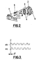
- the invention has foreseen that this embodiment incorporates a pair of optocouplers 4, of those where one of them has the role of emitter and the other that of receiver of the light signal emitted by the first, receiving said signal through the radial openings of the interior wheel 3.
- a pair of optocouplers 4 of those where one of them has the role of emitter and the other that of receiver of the light signal emitted by the first, receiving said signal through the radial openings of the interior wheel 3.
- Each stable position of the wheel corresponds with a function, such that, with the rotation of the wheel, it is possible to select, at will, the different functions that can be performed.
- the confirmation of the position chosen (that is, of the function selected) is carried out mechanically by the closing of a switch 6 in association with the wheel.
- the invention has furthermore fores
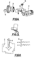
- Figure 4 shows a configuration entirely equivalent, from the functional point of view, to that described in relation with Figure 2, and comprises a part 8, provided with flexible pins, such that the rotation of said part causes the aforementioned flexible pins to close or open two independent circuits for the production of the out-of-phase signals that appear also represented in Figure 6 of the drawings; it also has a switch 6 for confirming the function chosen.
- the rotation of said part 8 is carried out by transmission through, for example, gearing which runs directly from the floating wheel to the part 8, through the intermediate part 5.
- the floating wheel 2 is made to rotate in the direction desired, depending on the function that is to be selected, and once its position has been reached, it is sufficient to depress the switch (6) to confirm the selection that has been made.
- the assembly includes means for generating the two signals aforementioned.
- Each signal serves, as has already been stated, to carry out a clearly differentiated mission.
- the pulse of the first signal can be employed advantageously to change the function in question (for example, increase or decrease the volume of a radio receiver, or whatever other function), whilst the second signal, out of phase, as is known, with respect to the first, determines the direction of rotation of the wheel, and therefore the form in which the selection is made from a pre-established initial position.
- the electronic means associated with the assembly includes a first microprocessor (not shown), in which the signals are received, and once encoded, it sends them to a second microprocessor, by means of which the output that corresponds to each function is selected. Moreover said microprocessors serve to reset the selected function to 0 after a determined period of time has elapsed without the pushbutton having been actuated, that is, if no signal is received from the latter.
- the monitoring of the function selected or active at any given moment is carried out preferably by means of a display unit, which can be incorporated in the wheel, or where appropriate by means of light-emitting indicators which can be fitted in the pertinent pushbutton.
- the steering wheel can also incorporate one or several pushbuttons, capable of being secured to whatever part thereof, namely, the framework or the covering of said wheel, making use of screws, clips or whatever other mechanical union that ensures the rigid fastening to the steering wheel and which impedes the projection thereof toward the occupant in the event of an accident.
- the location of said pushbuttons has to be as accessible as possible for the driver, the latter remaining in a comfortable position.
- they can be located on the front face or rear face of the steering wheel, on the arms, on the rim or on the central module.
- the invention has also foreseen that the device be situated in a position, raised, with respect to the plane of the steering wheel, such that the driver actuates it only in an intentional way, and not involuntarily when the former has his hands resting on said wheel.
- the device which has been described above offers the additional benefit that the wiring necessary for its correct installation is considerably reduced, since use is made of only one data bus.
Landscapes
- Engineering & Computer Science (AREA)
- Mechanical Engineering (AREA)
- Steering Controls (AREA)
- Steering Control In Accordance With Driving Conditions (AREA)
- Platform Screen Doors And Railroad Systems (AREA)
- Power Steering Mechanism (AREA)
- Length Measuring Devices With Unspecified Measuring Means (AREA)
Claims (6)
- Volant multifonction, spécialement un volant du type utilisé pour commander des véhicules à moteur, susceptible d'incorporer un dispositif de sélection et de commande actionnable et facilement accessible depuis une position confortable pour le conducteur, situé de telle manière qu'il ne puisse être actionné volontairement que par ledit conducteur, ledit dispositif étant apte à réaliser un nombre illimité de fonctions, qui comprend en outre : une roue (2) flottante à laquelle on peut accéder depuis une ou plusieurs positions du volant (1), caractérisé en ce que ladite roue flottante est susceptible de s'accoupler dans une roue (3) intermédiaire configurée pour présenter une multiplicité de formations radiales pourvues d'espaces ayant une géométrie et une inclinaison prédéterminées; des moyens d'émission et de réception de signaux lumineux, constitués par une paire d'optocoupleurs (4), du type de ceux où un émetteur transmet le signal lumineux au récepteur à travers la configuration de ladite roue (3) intermédiaire, de manière à ce que les zones photosensibles du récepteur, déphasées, permettent de connaítre l'angle à travers lequel on l'a tourné et le sens de rotation de la roue (2); un moyen (6) de commutation actionné mécaniquement, et en association avec ladite roue (2); des moyens (5) de mise en place stable de différents ajustements de la roue (2); une plaque (7) de circuit imprimé, en association avec l'ensemble, pour maintenir les composant de celui-ci, et des moyens électriques pour générer des signaux et traiter les signaux reçus.
- Volant multifonction selon la revendication 1, caractérisé en ce que chaque ajustement de la roue (2) a une fonction déterminée associée (ou la variation de la grandeur de ladite fonction), dont la confirmation est réalisée en pressant sur l'interrupteur (6) en association avec ladite roue (2).
- Volant multifonction selon la revendication 1, caractérisé en ce que l'on a prévu la génération de deux signaux "ab" et "ac" déphasés entre eux par un angle ϕ.
- Volant multifonction selon la revendication 1 en association avec la revendication 3, caractérisé en ce que les moyens électriques incluent deux microprocesseurs, du type de ceux où un premier microprocesseur réalise le codage des signaux reçus et les transmet au deuxième microprocesseur au moyen duquel on réalise l'activation des différentes sorties associées à chaque fonction respective.
- Volant multifonction selon la revendication 1, caractérisé en ce que dans une variante de la réalisation, on a prévu que le dispositif incorpore une partie (8) tournante, actionnable à travers un mécanisme de transmission ou similaire de la roue (2) flottante, pourvue de contacts flexibles, susceptibles de déplacer la plaque (7) de circuit imprimé, contacts au moyens desquels on réalise la sélection de deux circuits respectifs servant à générer les signaux "ab" et "ac" déphasés.
- Volant multifonction selon une ou plusieurs des revendications précédentes, caractérisé en ce que l'on inclut en outre la provision de moyens montrant la fonction active ou sélectionnée, lesdits moyens étant constitués par un panneau d'affichage ou une autre présentation situé sur le propre volant, ou là où il est considéré comme approprié, par des indicateurs photo-émetteurs associés aux boutons-poussoirs respectifs.
Applications Claiming Priority (2)
| Application Number | Priority Date | Filing Date | Title |
|---|---|---|---|
| ES200100047 | 2001-01-09 | ||
| ES200100047 | 2001-01-09 |
Publications (3)
| Publication Number | Publication Date |
|---|---|
| EP1221403A2 EP1221403A2 (fr) | 2002-07-10 |
| EP1221403A3 EP1221403A3 (fr) | 2003-05-07 |
| EP1221403B1 true EP1221403B1 (fr) | 2004-10-20 |
Family
ID=8496355
Family Applications (1)
| Application Number | Title | Priority Date | Filing Date |
|---|---|---|---|
| EP02380004A Expired - Lifetime EP1221403B1 (fr) | 2001-01-09 | 2002-01-09 | Volant multifonction |
Country Status (5)
| Country | Link |
|---|---|
| EP (1) | EP1221403B1 (fr) |
| AT (1) | ATE280069T1 (fr) |
| DE (1) | DE60201612T2 (fr) |
| ES (1) | ES2225746T3 (fr) |
| PT (1) | PT1221403E (fr) |
Cited By (1)
| Publication number | Priority date | Publication date | Assignee | Title |
|---|---|---|---|---|
| CN104220952A (zh) * | 2012-03-27 | 2014-12-17 | 德尔福技术有限公司 | 具有转动滚轮的命令选择器 |
Families Citing this family (4)
| Publication number | Priority date | Publication date | Assignee | Title |
|---|---|---|---|---|
| DE10212781A1 (de) * | 2002-03-22 | 2003-10-02 | Bayerische Motoren Werke Ag | Fahrzeug-Lenkrad mit zumindest einem Schalter oder Taster |
| DE10235159B4 (de) * | 2002-08-01 | 2007-09-13 | Daimlerchrysler Ag | Verstellbares Lenkrad für Kraftfahrzeuge |
| DE102007053689B4 (de) * | 2007-11-10 | 2017-12-28 | Leopold Kostal Gmbh & Co. Kg | Druck- und drehbetätigbares Bedienelement für ein Kraftfahrzeug |
| DE102010049082A1 (de) * | 2010-10-21 | 2012-04-26 | Gm Global Technology Operations Llc (N.D.Ges.D. Staates Delaware) | Lenkrad für ein Fahrzeug und Fahrzeug |
Family Cites Families (2)
| Publication number | Priority date | Publication date | Assignee | Title |
|---|---|---|---|---|
| JPH02288117A (ja) * | 1989-04-28 | 1990-11-28 | Toyoda Gosei Co Ltd | ステアリングホイールのスイッチ付ノブ |
| DE3917613A1 (de) * | 1989-05-31 | 1990-12-06 | Jirka Linhart | Lenkrad |
-
2002
- 2002-01-09 DE DE60201612T patent/DE60201612T2/de not_active Expired - Fee Related
- 2002-01-09 PT PT02380004T patent/PT1221403E/pt unknown
- 2002-01-09 EP EP02380004A patent/EP1221403B1/fr not_active Expired - Lifetime
- 2002-01-09 AT AT02380004T patent/ATE280069T1/de not_active IP Right Cessation
- 2002-01-09 ES ES02380004T patent/ES2225746T3/es not_active Expired - Lifetime
Cited By (2)
| Publication number | Priority date | Publication date | Assignee | Title |
|---|---|---|---|---|
| CN104220952A (zh) * | 2012-03-27 | 2014-12-17 | 德尔福技术有限公司 | 具有转动滚轮的命令选择器 |
| CN104220952B (zh) * | 2012-03-27 | 2016-01-13 | 德尔福技术有限公司 | 具有转动滚轮的命令选择器 |
Also Published As
| Publication number | Publication date |
|---|---|
| DE60201612D1 (de) | 2004-11-25 |
| DE60201612T2 (de) | 2005-11-03 |
| EP1221403A3 (fr) | 2003-05-07 |
| EP1221403A2 (fr) | 2002-07-10 |
| ES2225746T3 (es) | 2005-03-16 |
| PT1221403E (pt) | 2005-02-28 |
| ATE280069T1 (de) | 2004-11-15 |
Similar Documents
| Publication | Publication Date | Title |
|---|---|---|
| EP0822119B1 (fr) | Interrupteur multifonctions et système d'exploitation pour véhicules avec un tel interrupteur | |
| US6300939B1 (en) | Input device | |
| US7579559B2 (en) | Control knob having integrated functionality | |
| US20100040237A1 (en) | Remote control interface for replacement vehicle stereos | |
| JP2002347538A (ja) | 車載機器制御装置 | |
| JP2002283868A (ja) | 電子式ギヤシフトリセットを有する収納可能なシフタ | |
| RU2406636C2 (ru) | Узел рулевого колеса автомобиля и способ управления переносным функциональным компонентом | |
| JP2002149324A (ja) | 手動入力装置 | |
| EP1108611B1 (fr) | Arrangement d'interrupteurs pour volant de direction | |
| US4598237A (en) | Power window control apparatus | |
| EP1221403B1 (fr) | Volant multifonction | |
| KR100947729B1 (ko) | 스티어링 휠 햅틱 스위치 유니트 및 이를 구비하는스티어링 휠 햅틱 스위치 시스템 | |
| JP2006306378A (ja) | 車両空調用コントロール操作装置 | |
| JP2000003638A (ja) | ケーブルリールとコンビネーションスイッチとの取付構造 | |
| US7086292B2 (en) | Force-feedback input device | |
| EP1149730B1 (fr) | Unité de commutation pour volant de direction de véhicule automobile | |
| JP2004136802A (ja) | 自動車用ドアおよびドアトリム | |
| JP4433252B2 (ja) | リモコン送信機 | |
| GB2281956A (en) | Vehicle steering wheel with airbag and pressure sensor switch | |
| US7542744B2 (en) | Multimedia terminal | |
| JP2003153354A (ja) | ハプティック入力装置 | |
| KR101198833B1 (ko) | 자동차용 통합조작스위치 | |
| JP2004345552A (ja) | 車載機器遠隔操作システム | |
| KR20210151586A (ko) | 턴오버 스위치 유니트 및 차량용 변속 레인지 턴오버 유니트 | |
| CN215245081U (zh) | 转向装置 |
Legal Events
| Date | Code | Title | Description |
|---|---|---|---|
| PUAI | Public reference made under article 153(3) epc to a published international application that has entered the european phase |
Free format text: ORIGINAL CODE: 0009012 |
|
| AK | Designated contracting states |
Kind code of ref document: A2 Designated state(s): AT BE CH CY DE DK ES FI FR GB GR IE IT LI LU MC NL PT SE TR |
|
| AX | Request for extension of the european patent |
Free format text: AL;LT;LV;MK;RO;SI |
|
| PUAL | Search report despatched |
Free format text: ORIGINAL CODE: 0009013 |
|
| AK | Designated contracting states |
Designated state(s): AT BE CH CY DE DK ES FI FR GB GR IE IT LI LU MC NL PT SE TR |
|
| AX | Request for extension of the european patent |
Extension state: AL LT LV MK RO SI |
|
| 17P | Request for examination filed |
Effective date: 20031104 |
|
| AKX | Designation fees paid |
Designated state(s): AT BE CH CY DE DK ES FI FR GB GR IE IT LI LU MC NL PT SE TR |
|
| GRAP | Despatch of communication of intention to grant a patent |
Free format text: ORIGINAL CODE: EPIDOSNIGR1 |
|
| GRAS | Grant fee paid |
Free format text: ORIGINAL CODE: EPIDOSNIGR3 |
|
| GRAA | (expected) grant |
Free format text: ORIGINAL CODE: 0009210 |
|
| AK | Designated contracting states |
Kind code of ref document: B1 Designated state(s): AT BE CH CY DE DK ES FI FR GB GR IE IT LI LU MC NL PT SE TR |
|
| PG25 | Lapsed in a contracting state [announced via postgrant information from national office to epo] |
Ref country code: TR Free format text: LAPSE BECAUSE OF FAILURE TO SUBMIT A TRANSLATION OF THE DESCRIPTION OR TO PAY THE FEE WITHIN THE PRESCRIBED TIME-LIMIT Effective date: 20041020 Ref country code: AT Free format text: LAPSE BECAUSE OF FAILURE TO SUBMIT A TRANSLATION OF THE DESCRIPTION OR TO PAY THE FEE WITHIN THE PRESCRIBED TIME-LIMIT Effective date: 20041020 Ref country code: FI Free format text: LAPSE BECAUSE OF FAILURE TO SUBMIT A TRANSLATION OF THE DESCRIPTION OR TO PAY THE FEE WITHIN THE PRESCRIBED TIME-LIMIT Effective date: 20041020 Ref country code: LI Free format text: LAPSE BECAUSE OF FAILURE TO SUBMIT A TRANSLATION OF THE DESCRIPTION OR TO PAY THE FEE WITHIN THE PRESCRIBED TIME-LIMIT Effective date: 20041020 Ref country code: BE Free format text: LAPSE BECAUSE OF FAILURE TO SUBMIT A TRANSLATION OF THE DESCRIPTION OR TO PAY THE FEE WITHIN THE PRESCRIBED TIME-LIMIT Effective date: 20041020 Ref country code: CH Free format text: LAPSE BECAUSE OF FAILURE TO SUBMIT A TRANSLATION OF THE DESCRIPTION OR TO PAY THE FEE WITHIN THE PRESCRIBED TIME-LIMIT Effective date: 20041020 Ref country code: NL Free format text: LAPSE BECAUSE OF FAILURE TO SUBMIT A TRANSLATION OF THE DESCRIPTION OR TO PAY THE FEE WITHIN THE PRESCRIBED TIME-LIMIT Effective date: 20041020 |
|
| REG | Reference to a national code |
Ref country code: GB Ref legal event code: FG4D |
|
| REG | Reference to a national code |
Ref country code: CH Ref legal event code: EP |
|
| REG | Reference to a national code |
Ref country code: IE Ref legal event code: FG4D |
|
| REG | Reference to a national code |
Ref country code: SE Ref legal event code: TRGR |
|
| REF | Corresponds to: |
Ref document number: 60201612 Country of ref document: DE Date of ref document: 20041125 Kind code of ref document: P |
|
| PG25 | Lapsed in a contracting state [announced via postgrant information from national office to epo] |
Ref country code: CY Free format text: LAPSE BECAUSE OF FAILURE TO SUBMIT A TRANSLATION OF THE DESCRIPTION OR TO PAY THE FEE WITHIN THE PRESCRIBED TIME-LIMIT Effective date: 20050109 Ref country code: LU Free format text: LAPSE BECAUSE OF NON-PAYMENT OF DUE FEES Effective date: 20050109 |
|
| PG25 | Lapsed in a contracting state [announced via postgrant information from national office to epo] |
Ref country code: IE Free format text: LAPSE BECAUSE OF NON-PAYMENT OF DUE FEES Effective date: 20050110 |
|
| PG25 | Lapsed in a contracting state [announced via postgrant information from national office to epo] |
Ref country code: DK Free format text: LAPSE BECAUSE OF FAILURE TO SUBMIT A TRANSLATION OF THE DESCRIPTION OR TO PAY THE FEE WITHIN THE PRESCRIBED TIME-LIMIT Effective date: 20050120 Ref country code: GR Free format text: LAPSE BECAUSE OF FAILURE TO SUBMIT A TRANSLATION OF THE DESCRIPTION OR TO PAY THE FEE WITHIN THE PRESCRIBED TIME-LIMIT Effective date: 20050120 |
|
| PG25 | Lapsed in a contracting state [announced via postgrant information from national office to epo] |
Ref country code: MC Free format text: LAPSE BECAUSE OF NON-PAYMENT OF DUE FEES Effective date: 20050131 |
|
| REG | Reference to a national code |
Ref country code: PT Ref legal event code: SC4A Free format text: AVAILABILITY OF NATIONAL TRANSLATION Effective date: 20041221 |
|
| REG | Reference to a national code |
Ref country code: ES Ref legal event code: FG2A Ref document number: 2225746 Country of ref document: ES Kind code of ref document: T3 |
|
| REG | Reference to a national code |
Ref country code: CH Ref legal event code: PL |
|
| NLV1 | Nl: lapsed or annulled due to failure to fulfill the requirements of art. 29p and 29m of the patents act | ||
| ET | Fr: translation filed | ||
| PLBE | No opposition filed within time limit |
Free format text: ORIGINAL CODE: 0009261 |
|
| STAA | Information on the status of an ep patent application or granted ep patent |
Free format text: STATUS: NO OPPOSITION FILED WITHIN TIME LIMIT |
|
| 26N | No opposition filed |
Effective date: 20050721 |
|
| REG | Reference to a national code |
Ref country code: IE Ref legal event code: MM4A |
|
| PGFP | Annual fee paid to national office [announced via postgrant information from national office to epo] |
Ref country code: GB Payment date: 20060104 Year of fee payment: 5 |
|
| PGFP | Annual fee paid to national office [announced via postgrant information from national office to epo] |
Ref country code: PT Payment date: 20060111 Year of fee payment: 5 |
|
| PGFP | Annual fee paid to national office [announced via postgrant information from national office to epo] |
Ref country code: SE Payment date: 20060118 Year of fee payment: 5 |
|
| PG25 | Lapsed in a contracting state [announced via postgrant information from national office to epo] |
Ref country code: SE Free format text: LAPSE BECAUSE OF NON-PAYMENT OF DUE FEES Effective date: 20070110 |
|
| PG25 | Lapsed in a contracting state [announced via postgrant information from national office to epo] |
Ref country code: PT Free format text: LAPSE BECAUSE OF NON-PAYMENT OF DUE FEES Effective date: 20070709 |
|
| REG | Reference to a national code |
Ref country code: PT Ref legal event code: MM4A Free format text: LAPSE DUE TO NON-PAYMENT OF FEES Effective date: 20070709 |
|
| EUG | Se: european patent has lapsed | ||
| GBPC | Gb: european patent ceased through non-payment of renewal fee |
Effective date: 20070109 |
|
| PG25 | Lapsed in a contracting state [announced via postgrant information from national office to epo] |
Ref country code: GB Free format text: LAPSE BECAUSE OF NON-PAYMENT OF DUE FEES Effective date: 20070109 |
|
| PGFP | Annual fee paid to national office [announced via postgrant information from national office to epo] |
Ref country code: ES Payment date: 20081215 Year of fee payment: 8 |
|
| PGFP | Annual fee paid to national office [announced via postgrant information from national office to epo] |
Ref country code: DE Payment date: 20090122 Year of fee payment: 8 |
|
| PGFP | Annual fee paid to national office [announced via postgrant information from national office to epo] |
Ref country code: IT Payment date: 20090127 Year of fee payment: 8 |
|
| PGFP | Annual fee paid to national office [announced via postgrant information from national office to epo] |
Ref country code: FR Payment date: 20090115 Year of fee payment: 8 |
|
| REG | Reference to a national code |
Ref country code: FR Ref legal event code: ST Effective date: 20100930 |
|
| PG25 | Lapsed in a contracting state [announced via postgrant information from national office to epo] |
Ref country code: FR Free format text: LAPSE BECAUSE OF NON-PAYMENT OF DUE FEES Effective date: 20100201 |
|
| PG25 | Lapsed in a contracting state [announced via postgrant information from national office to epo] |
Ref country code: DE Free format text: LAPSE BECAUSE OF NON-PAYMENT OF DUE FEES Effective date: 20100803 |
|
| PG25 | Lapsed in a contracting state [announced via postgrant information from national office to epo] |
Ref country code: IT Free format text: LAPSE BECAUSE OF NON-PAYMENT OF DUE FEES Effective date: 20100109 |
|
| REG | Reference to a national code |
Ref country code: ES Ref legal event code: FD2A Effective date: 20110404 |
|
| PG25 | Lapsed in a contracting state [announced via postgrant information from national office to epo] |
Ref country code: ES Free format text: LAPSE BECAUSE OF NON-PAYMENT OF DUE FEES Effective date: 20110322 |
|
| PG25 | Lapsed in a contracting state [announced via postgrant information from national office to epo] |
Ref country code: ES Free format text: LAPSE BECAUSE OF NON-PAYMENT OF DUE FEES Effective date: 20100110 |