EP1221406A2 - Vorrichtung zur Lagerung von Fahrrädern - Google Patents
Vorrichtung zur Lagerung von Fahrrädern Download PDFInfo
- Publication number
- EP1221406A2 EP1221406A2 EP01204877A EP01204877A EP1221406A2 EP 1221406 A2 EP1221406 A2 EP 1221406A2 EP 01204877 A EP01204877 A EP 01204877A EP 01204877 A EP01204877 A EP 01204877A EP 1221406 A2 EP1221406 A2 EP 1221406A2
- Authority
- EP
- European Patent Office
- Prior art keywords
- carriage
- bicycle
- suspension hook
- conveyor chain
- clamp
- Prior art date
- Legal status (The legal status is an assumption and is not a legal conclusion. Google has not performed a legal analysis and makes no representation as to the accuracy of the status listed.)
- Withdrawn
Links
- 239000000725 suspension Substances 0.000 claims abstract description 49
- 239000000463 material Substances 0.000 description 2
- 229920000271 Kevlar® Polymers 0.000 description 1
- 230000003213 activating effect Effects 0.000 description 1
- 230000005484 gravity Effects 0.000 description 1
- 239000004761 kevlar Substances 0.000 description 1
- 239000002184 metal Substances 0.000 description 1
- 238000000034 method Methods 0.000 description 1
- 239000004033 plastic Substances 0.000 description 1
- 239000012858 resilient material Substances 0.000 description 1
Images
Classifications
-
- B—PERFORMING OPERATIONS; TRANSPORTING
- B62—LAND VEHICLES FOR TRAVELLING OTHERWISE THAN ON RAILS
- B62H—CYCLE STANDS; SUPPORTS OR HOLDERS FOR PARKING OR STORING CYCLES; APPLIANCES PREVENTING OR INDICATING UNAUTHORIZED USE OR THEFT OF CYCLES; LOCKS INTEGRAL WITH CYCLES; DEVICES FOR LEARNING TO RIDE CYCLES
- B62H3/00—Separate supports or holders for parking or storing cycles
- B62H3/12—Hanging-up devices
Definitions
- the invention relates to a device for storing bicycles, said device comprising an endless conveyor chain which can be driven and is supported at a distance above the ground by guiding means, by which conveyor, by means of suspension hooks, the front wheel of a bicycle can be suspended, a manipulator being situated where a bicycle can be put: into and removed from the device, said manipulator comprising a beam along which a carriage is movable, said carriage being provided with means capable of engaging the front wheel of the bicycle for moving it upwards and transferring it to a suspension hook and vice versa.
- Such a device is known from EP-A-1.162.131.
- This known device has the drawback that the bicycle must be guided by a person when its front wheel is picked-up and brought upward. Namely, e.g. the rear fender must be prevented from contacting the ground or grating along the ground on moving the bicycle's front wheel upwards. The same holds good in case of bringing the bicycle downwards when it should be removed from the storage. In connection with the location of the centre of gravity of the bicycle, thus, in both cases, the luggage rack or the saddle has to be pulled so that the rear wheel will move away from the manipulator and the rear fender will remain free from the ground.
- a further drawback of said known device is that the hook coupled to the carriage engages the uppermost part of the front wheel.
- the wheel When the hook engages at a lower position, the wheel will start rotating as soon as it is lifted from the ground.
- a basket is mounted above the front wheel, this will cause problems. It is also possible that the fender at the front wheel will be damaged by the hook.
- the object of the invention is to remove these drawbacks and to that end provides for, that the carriage is provided with a clamp for clamping the front wheel of a bicycle and that the beam of the manipulator, along which the carriage moves, is pivotably mounted to a pivot shaft near its upper end, in such a way that the beam can pivot within a plane being square to the longitudinal direction of the conveyor chain, means being present for moving the beam from an inwardly slanted position into an outwardly slanted position, and vice versa, said conveyor chain being provided with hooks, from which the front wheel of a bicycle can be suspended.
- the beam of the robot When picking up a bicycle, the beam of the robot will be slanted outwards and the front wheel will be clamped to the carriage, to wit approximately at the level of the wheel shaft. Then, on moving the carriage upwards, the wheel will maintain its fixed position in relation to said carriage, and the further part of the bicycle will rotate in relation to the wheel.
- the beam can take up such an outwardly slanted position, that the rear fender of the bicycle will not contact the ground when its front wheel is moved upwards. After the front wheel has been moved upwards across a sufficient distance, the beam will be pivoted inwards so that the bicycle will suspend from the carriage more or less freely.
- the bent portion of the suspension hook can be brought under the wheel rim, such as by moving the conveyor chain.
- the carriage can be moved slightly downwards, so that the wheel rim will come to bear in the suspension hook and the clamp can release the wheel.
- the clamp can be moved out of the way of the bicycle being conveyed by the conveyor chain.
- the clamp can be designed in such a way, that a first part of it is fixedly connected to the carriage, whereas the counterpart is movable, at least one of the parts extending across such a length, that it contacts the rim of the wheel or the tyre located on it, at two spaced-apart positions.
- a bicycle storage will mostly have a compressor device for pumping-up bicycle tyres.
- the counterpart of the clamp can be constituted by at least one inflatable air cushion, at one side being directed to the first part of the clamp which is fixedly connected to the carriage and at the other side contacting a support portion fixedly connected to the carriage.
- Such an air cushion can of course be easily adapted to the shape of the rim and the bicycle tyre located on it so that the bicycle wheel is always firmly clamped.
- the person can release the steering rod of the bicycle and need not do anything further. Thus, he will remain outside of the space screened by the wall and can not be contacted by moving parts.
- the carriage will be provided with at least one switch, which, in the lowermost or uppermost position of the carriage, can be operated directly or indirectly by the front wheel of a bicycle in order to activate the clamp connected to the carriage.
- the switch can be directly operated in that it will contact the front wheel of the bicycle.
- a vicinity switch or a photo cell or a similar member detecting the presence of a front wheel and actuating the switch activating the clamp.
- the front wheel When bringing a bicycle into the device, the front wheel can be ridden against the switch, so that first the clamp will be activated and then the carriage will be moved upwards. Naturally, movement of the carriage will take place in the known manner.
- the front wheel of the bicycle can then be brought in the vicinity of the carriage by moving the suspension hook, such as with the help of the conveyor chain. After that, the carriage can be moved upward and the beam of the manipulator can be pivoted so that the wheel of the bicycle will contact the switch of the carriage and the wheel will be clamped. After that, the carriage can be moved downward and the further procedure can be performed in order bring the bicycle out of the storage.
- a guiding trough fcr the wheels of a bicycle will be provided on the ground near the manipulator.
- an electrically or pneumatically driven rod system For pivoting the beam of the manipulator, one can use an electrically or pneumatically driven rod system.
- the bent portion of the suspension hook can be brought underneath the wheel rim or from it, by moving the conveyor chain.
- the conveyor chain with all possible bicycles suspending from it should then be brought in motion and be moved across a rather small distance.
- a bicycle grabbed by a clamp should obviously not be able to contact the bicycle hanging next to it. This will have to be taken into account when determining the distances between bicycles.
- the suspension hook is pivotably connected to the conveyor chain, in such a way that the pivot: axis is square to the longitudinal direction of the conveyor chain and extends parallel to the plane in which the conveyor chain is situated, the suspension hook being movable between two end positions, said suspension hook and carriage being provided with members capable of cooperating with one another in order to bring the suspension hook from ore end position to the other end position.
- the suspension hook can e.g. be held in both end positions because a tension spring has been mounted between the suspension hook and a fixed point of the conveyor chain, said tension spring passing the pivot shaft when moving the suspension hook from one end position to the other, said suspension hook being provided with cams capable of cooperating with a pushing element connected to the carriage.
- suspension hook will then be completely mechanically operated.
- electrically or pneumatically operated means connected to the carriage, which will engage parts of the suspension hook when moving the carriage upward.
- EP-A-0 659 958 is referred to, which describes a device for storing bicycles, in which every bicycle is hanged in a separate cage.
- a number of cages are guided along two elongated rods extending in parallel, connecting to one another by semi-circular parts.
- a conveyor chain for moving the cages extends along the upper system.
- every cage there is a pivotable rod system for bringing the bicycle concerned into the vertical position and holding it in that position.
- the cage will have to be at least so wide, that the bicycle having the widest steering rod can be received in it.
- the bicycles can be suspended at alternate heights, as a result of which more bicycles per unit of length can be accommodated.
- only one manipulator arranged on one location is required, whereas the mass to be moved is considerably lower, since only the bicycles need be moved and not the cages with their individual rod systems as well, as is the case with the known device.
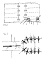
- Fig. 1 shows a plan of a bicycle storage 1 comprising a number of compartments 2, each of which incorporating a device 3 suitable for storing a number of bicycles 4, as appears from Fig. 2.
- each device 3 comprises a conveyor chain 5, provided with a number of suspension hooks 6.
- the conveyor chain 5 is supported by guiding means 7 consisting of two straight paths 8 extending in parallel and two bends 9.
- a bicycle 4 can be brought into the device 3 or be removed from it, as it has been illustrated in more detail in Fig. 2.
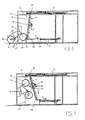
- Figures 3 and 4 show in particular an elevational view of the manipulator 11 as it is used for bringing the front wheel 16 of a bicycle 4 into a suspension hook 6 and removing it from said hook.
- the manipulator 11 comprises a beam 12 along which a carriage 13 is movable, such as by means of a motor-driven endless chain 14, for example.
- the carriage 13 is provided with a clamp 15, comprising a first part 17 being fixedly connected to the carriage 13 and a counterpart 18, which can be constituted in particular by at least one inflatable air cushion, not further indicated, having one side facing first part 17 and the other side bearing against a supporting part fixedly connected to the carriage and not further indicated.
- the air cushion will have been made of a firm yet sufficiently flexible material, such as rubber or a plastic, such as kevlar, or a similar material.
- the first part 17 of the clamp 15, which part is fixedly connected to the carriage, will generally consist of metal, and will be coated with a slightly resilient material in order to prevent damage to the wheel rim.
- the beam 12 is suspended from a pivot shaft 19 and can be pivoted by means of a rod 20 pivotably connected to it, having its other end pivotably coupled to a rod 21 being movable only in axial direction.
- a rod 20 pivotably connected to it, having its other end pivotably coupled to a rod 21 being movable only in axial direction.
- the bicycle has been ridden through an opening in the wall 23 not further indicated, so that the steering rod 24 of the bicycle is approximately in the opening.
- the person wishing to store the bicycle will thus remain standing at the outside of wall 23 and can, after the front wheel has been clamped, let go of the steering rod.
- conveyor chain 5 can be activated so that a suspension hook 6, fixedly connected to, it will come to fall underneath the rim 25.
- the carriage 13 will then be moved slightly downward so that the rim will come to bear in the hook. Then, one releases air from the air cushion of counterpart 18 of the clamp 15 so that the wheel will be released.
- the carriage 13 can be moved further downward, so that the conveyor chain 5 can continue moving without the bicycle contacting the carriage 13. At the same time, space will become avaible for receiving a subsequent bicycle. When removing a bicycle from the device, one will act in the reverse order.
- Fig. 4 shows the position of the bicycle 4 when it has been suspended in the hook 6 and has been released by the clamp 15 of the carriage 13. The carriage 13 will then move downward as indicated by arrow S.
- a guiding trough 27 For guiding the wheels 16 and 26 of a bicycle 4 when bringing it into the storage and removing it from the storage, a guiding trough 27 will have been mounted on the ground. This is particularly important when the bicycle moves downward and is pushed out.
- the suspension hook can be provided with means not further indicated, which can be activated and deactivated by the carriage only.
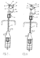
- Figures 5 and 6 illustrate the possibility that a suspension hook 6 is connected to the conveyor chain 5 by means of a pivot shaft 28.
- a tension spring 29 extends between the suspension hook 6 and a fixed location of the conveyor chain 5. When pivoting the suspension hook 6 from one end position to the other end position, the tension spring 29 passes the pivot shaft 28, so that the suspension hook always takes up the stable end position.
- the end positions of the suspension hook 6 can be achieved in a known manner, such as by stop members at the conveyor chain.
- the carriage 13 When removing a bicycle, the carriage 13 is brought upward across a certain distance so that the wheel 16 can be clamped. Then, the carriage is moved further upward and the pushing element 30 will engage a cam 32 of the suspension hook 6, so that the suspension hook 6 will move back to the end position illustrated in Figure 5. A portion of the pushing element 30 is pivotable around the pivot axis 33, so that it can pass the cam 30 and subsequently move back to its starting position by a spring not illustrated.
Landscapes
- Engineering & Computer Science (AREA)
- Mechanical Engineering (AREA)
- Handcart (AREA)
- Fittings On The Vehicle Exterior For Carrying Loads, And Devices For Holding Or Mounting Articles (AREA)
Applications Claiming Priority (2)
| Application Number | Priority Date | Filing Date | Title |
|---|---|---|---|
| NL1017026 | 2001-01-03 | ||
| NL1017026A NL1017026C2 (nl) | 2001-01-03 | 2001-01-03 | Inrichting voor het stallen van fietsen, voorzien van een manipulator voor het overbrengen van een fiets. |
Publications (2)
| Publication Number | Publication Date |
|---|---|
| EP1221406A2 true EP1221406A2 (de) | 2002-07-10 |
| EP1221406A3 EP1221406A3 (de) | 2005-01-12 |
Family
ID=19772678
Family Applications (1)
| Application Number | Title | Priority Date | Filing Date |
|---|---|---|---|
| EP01204877A Withdrawn EP1221406A3 (de) | 2001-01-03 | 2001-12-13 | Vorrichtung zur Lagerung von Fahrrädern |
Country Status (2)
| Country | Link |
|---|---|
| EP (1) | EP1221406A3 (de) |
| NL (1) | NL1017026C2 (de) |
Cited By (3)
| Publication number | Priority date | Publication date | Assignee | Title |
|---|---|---|---|---|
| EP1698749A3 (de) * | 2005-02-25 | 2010-04-21 | P.M. Van Loon Beheer B.V. | Kontrolleinheit für ein Schloss |
| DE102008059073A1 (de) * | 2008-11-26 | 2010-05-27 | Ströer Out-of-Home Media AG | Entleihsystem für Fahrräder und Verfahren zum Entleihen und zur Rückgabe von Fahrrädern |
| WO2015108324A1 (ko) * | 2014-01-20 | 2015-07-23 | 권영종 | 층고 확장 이동식 자동화 자전거 보관소 |
Families Citing this family (1)
| Publication number | Priority date | Publication date | Assignee | Title |
|---|---|---|---|---|
| CN109881944A (zh) * | 2019-04-12 | 2019-06-14 | 上海电力学院 | 摩天轮式自行车停车架 |
Citations (1)
| Publication number | Priority date | Publication date | Assignee | Title |
|---|---|---|---|---|
| EP1162131A1 (de) | 2000-06-07 | 2001-12-12 | Fa. Sy- Minc | Vorrichtung zur Lagerung von Fahrrädern |
Family Cites Families (6)
| Publication number | Priority date | Publication date | Assignee | Title |
|---|---|---|---|---|
| DE4128578A1 (de) * | 1990-08-31 | 1992-03-26 | Immler Josef Dipl Ing Fh | Aufbewahrungsvorrichtung fuer fahrraeder |
| WO1993007043A1 (de) * | 1991-10-11 | 1993-04-15 | Joe Burri | Vorrichtung zum aufbewahren von gegenständen |
| DE9319662U1 (de) * | 1993-12-21 | 1994-02-10 | Odenwaldwerke Rittersbach GmbH Fahrzeugbau und Katastrophenschutzsysteme, 74834 Elztal | Karusell-Fahrradhänger |
| WO1996007581A1 (de) * | 1994-09-05 | 1996-03-14 | Gerhard Arnold | Fahrradhalter |
| DE19621222A1 (de) * | 1996-05-25 | 1997-11-27 | Metallbau Bruno Vaeth Gmbh | Fahrradständer |
| NL1011951C2 (nl) * | 1999-05-03 | 2000-11-06 | Sy Minc Fa | Inrichting voor het stallen van fietsen. |
-
2001
- 2001-01-03 NL NL1017026A patent/NL1017026C2/nl not_active IP Right Cessation
- 2001-12-13 EP EP01204877A patent/EP1221406A3/de not_active Withdrawn
Patent Citations (1)
| Publication number | Priority date | Publication date | Assignee | Title |
|---|---|---|---|---|
| EP1162131A1 (de) | 2000-06-07 | 2001-12-12 | Fa. Sy- Minc | Vorrichtung zur Lagerung von Fahrrädern |
Cited By (5)
| Publication number | Priority date | Publication date | Assignee | Title |
|---|---|---|---|---|
| EP1698749A3 (de) * | 2005-02-25 | 2010-04-21 | P.M. Van Loon Beheer B.V. | Kontrolleinheit für ein Schloss |
| DE102008059073A1 (de) * | 2008-11-26 | 2010-05-27 | Ströer Out-of-Home Media AG | Entleihsystem für Fahrräder und Verfahren zum Entleihen und zur Rückgabe von Fahrrädern |
| DE102008059073B4 (de) * | 2008-11-26 | 2012-03-01 | Ströer Out-of-Home Media AG | Entleihsystem für Fahrräder und Verfahren zum Entleihen und zur Rückgabe von Fahrrädern |
| WO2015108324A1 (ko) * | 2014-01-20 | 2015-07-23 | 권영종 | 층고 확장 이동식 자동화 자전거 보관소 |
| US9932748B2 (en) | 2014-01-20 | 2018-04-03 | Jong-Seok Lee | Movable and height-extensible automated bicycle storage |
Also Published As
| Publication number | Publication date |
|---|---|
| NL1017026C2 (nl) | 2002-07-05 |
| EP1221406A3 (de) | 2005-01-12 |
Similar Documents
| Publication | Publication Date | Title |
|---|---|---|
| US4313269A (en) | Feeding machine for sheets | |
| FI103959B (fi) | Menetelmä ja laite koukuista riippuvien tavaroiden lajittelemiseksi | |
| EP1221406A2 (de) | Vorrichtung zur Lagerung von Fahrrädern | |
| CN212402315U (zh) | 搬运机器人 | |
| US20070068773A1 (en) | Device for the transfer of garment | |
| CN104321238B (zh) | 运输机用导引轨道件和包括导引轨道件的运输机 | |
| WO2001055013A1 (en) | Retaining device for a conveyor belt assembly | |
| CN212558399U (zh) | 物品取出机构及搬运机器人 | |
| EP1162131A1 (de) | Vorrichtung zur Lagerung von Fahrrädern | |
| CN114132742B (zh) | 一种软袋上料装置及灯检机 | |
| EP1771294A1 (de) | Reifenrohlings-fördervorrichtung | |
| EP3072396B1 (de) | Handhabungssystem und -verfahren für wurstförmige Produkte | |
| JPH0611609B2 (ja) | 環状楔形グリッパを有するコンベヤハンガ装置 | |
| CA2237769C (en) | Automated sorting apparatus and system | |
| JP2022504486A (ja) | ボトル型の個別物品を保管及び回収する取扱装置 | |
| GB2220405A (en) | Gripper arrangement, e.g. for garment material. | |
| JP4271759B2 (ja) | 吊り下げ搬送装置 | |
| EP0401827B1 (de) | Vorrichtung zum Absaugen von auf Vorgarnspulen verbliebenen Luntenresten | |
| CN210122363U (zh) | 输送装置及拆码盘机 | |
| CN210117007U (zh) | 收放板机 | |
| NL1011951C2 (nl) | Inrichting voor het stallen van fietsen. | |
| JPH10291625A (ja) | 吊り下げ搬送装置 | |
| EP4124591A1 (de) | Kleiderbügel mit mit transportelementen beweglich verbundenen trägerelementen | |
| JPH10291627A (ja) | 吊り下げ搬送装置 | |
| NL1011646C2 (nl) | Kledingbufferinrichting. |
Legal Events
| Date | Code | Title | Description |
|---|---|---|---|
| PUAI | Public reference made under article 153(3) epc to a published international application that has entered the european phase |
Free format text: ORIGINAL CODE: 0009012 |
|
| AK | Designated contracting states |
Kind code of ref document: A2 Designated state(s): AT BE CH CY DE DK ES FI FR GB GR IE IT LI LU MC NL PT SE TR |
|
| AX | Request for extension of the european patent |
Free format text: AL;LT;LV;MK;RO;SI |
|
| PUAL | Search report despatched |
Free format text: ORIGINAL CODE: 0009013 |
|
| AK | Designated contracting states |
Kind code of ref document: A3 Designated state(s): AT BE CH CY DE DK ES FI FR GB GR IE IT LI LU MC NL PT SE TR |
|
| AX | Request for extension of the european patent |
Extension state: AL LT LV MK RO SI |
|
| RIC1 | Information provided on ipc code assigned before grant |
Ipc: 7E 04H 6/00 B Ipc: 7B 62H 3/12 A |
|
| 17P | Request for examination filed |
Effective date: 20050711 |
|
| AKX | Designation fees paid |
Designated state(s): AT BE CH CY DE DK ES FI FR GB GR IE IT LI LU MC NL PT SE TR |
|
| GRAP | Despatch of communication of intention to grant a patent |
Free format text: ORIGINAL CODE: EPIDOSNIGR1 |
|
| STAA | Information on the status of an ep patent application or granted ep patent |
Free format text: STATUS: THE APPLICATION IS DEEMED TO BE WITHDRAWN |
|
| 18D | Application deemed to be withdrawn |
Effective date: 20060328 |