EP1221410A2 - Procédé et dispositif pour emballer des articles - Google Patents
Procédé et dispositif pour emballer des articles Download PDFInfo
- Publication number
- EP1221410A2 EP1221410A2 EP01130784A EP01130784A EP1221410A2 EP 1221410 A2 EP1221410 A2 EP 1221410A2 EP 01130784 A EP01130784 A EP 01130784A EP 01130784 A EP01130784 A EP 01130784A EP 1221410 A2 EP1221410 A2 EP 1221410A2
- Authority
- EP
- European Patent Office
- Prior art keywords
- cassette
- transfer
- packaging
- stack
- bag
- Prior art date
- Legal status (The legal status is an assumption and is not a legal conclusion. Google has not performed a legal analysis and makes no representation as to the accuracy of the status listed.)
- Granted
Links
- 238000000034 method Methods 0.000 title claims abstract description 28
- 238000004806 packaging method and process Methods 0.000 title claims description 45
- 238000012546 transfer Methods 0.000 claims abstract description 54
- 238000007789 sealing Methods 0.000 claims abstract description 5
- 230000033001 locomotion Effects 0.000 claims description 21
- 230000006835 compression Effects 0.000 claims description 8
- 238000007906 compression Methods 0.000 claims description 8
- 230000008569 process Effects 0.000 claims description 3
- 238000006073 displacement reaction Methods 0.000 claims description 2
- 238000012856 packing Methods 0.000 abstract description 6
- 238000011161 development Methods 0.000 description 13
- 230000018109 developmental process Effects 0.000 description 13
- 238000003466 welding Methods 0.000 description 7
- 238000013459 approach Methods 0.000 description 2
- 230000008859 change Effects 0.000 description 2
- 230000000694 effects Effects 0.000 description 2
- 238000003780 insertion Methods 0.000 description 2
- 230000037431 insertion Effects 0.000 description 2
- 238000012549 training Methods 0.000 description 2
- 230000015572 biosynthetic process Effects 0.000 description 1
- 238000004140 cleaning Methods 0.000 description 1
- 238000010276 construction Methods 0.000 description 1
- 238000005755 formation reaction Methods 0.000 description 1
- 230000007257 malfunction Effects 0.000 description 1
- 238000012858 packaging process Methods 0.000 description 1
- 230000009467 reduction Effects 0.000 description 1
- 230000003014 reinforcing effect Effects 0.000 description 1
- 230000007704 transition Effects 0.000 description 1
Images


Classifications
-
- B—PERFORMING OPERATIONS; TRANSPORTING
- B65—CONVEYING; PACKING; STORING; HANDLING THIN OR FILAMENTARY MATERIAL
- B65B—MACHINES, APPARATUS OR DEVICES FOR, OR METHODS OF, PACKAGING ARTICLES OR MATERIALS; UNPACKING
- B65B5/00—Packaging individual articles in containers or receptacles, e.g. bags, sacks, boxes, cartons, cans, jars
- B65B5/06—Packaging groups of articles, the groups being treated as single articles
- B65B5/067—Packaging groups of articles, the groups being treated as single articles in bags
-
- B—PERFORMING OPERATIONS; TRANSPORTING
- B65—CONVEYING; PACKING; STORING; HANDLING THIN OR FILAMENTARY MATERIAL
- B65B—MACHINES, APPARATUS OR DEVICES FOR, OR METHODS OF, PACKAGING ARTICLES OR MATERIALS; UNPACKING
- B65B63/00—Auxiliary devices, not otherwise provided for, for operating on articles or materials to be packaged
- B65B63/02—Auxiliary devices, not otherwise provided for, for operating on articles or materials to be packaged for compressing or compacting articles or materials prior to wrapping or insertion in containers or receptacles
- B65B63/022—Auxiliary devices, not otherwise provided for, for operating on articles or materials to be packaged for compressing or compacting articles or materials prior to wrapping or insertion in containers or receptacles using compressing chambers or plates moving in an endless path
Definitions
- the invention relates to an apparatus and a method for packaging Items in bags.
- the items to be packaged can be Trade stacks of flat items. Due to the type of packaging with Side gussets are inserted at the cross section of the pack certain geometric conditions. The pack must not be higher turn out to be wide. This is the case for products with low content given.
- the flat articles are, due to the construction of the devices, with which these flat individual articles are formed, delivered upright. Becomes the height / width ratio in the packaging must be below this Objects are arranged horizontally.
- the articles are often around compressible objects, for example panty liners, Cleaning wipes or other fluffy products.
- the invention is based on the object of a method and a device To propose to pack items in bags, that with works great reliability and offers the opportunity to understand the effects of Reduce interference.
- the invention proposes a device with the Features mentioned in claim 1 and a method with the in claim 22 mentioned features. Developments of the invention are the subject of Subclaims, the wording as well as the wording of the Summary made by reference to the content of the description becomes.
- the device thus uses a slide that acts as an upper slide on one circulating chain is attached. So this slider is not going back and forth moved, but along a closed path, the return path in at a different height.
- the sliding distance of the Product pusher is fixed. The slider first brings the one to be packed Object in the filling cassette, from which the object in the Bag station is brought. From there, he will then use the Accompanying cassette brought to the locking station.
- the Packaging cassette is arranged and designed such that the slide in the loading position an object to be packed into the cassette can insert.
- the packaging cassette can be provided in this way is movable that it together with the object to be packaged in retract an opened bag and stand there in the transfer position remains. The object to be packaged is therefore pushed in as long as this is still arranged in the packaging cassette.
- the packaging cassette can have smooth side walls, a smooth one Bottom and also a smooth top with a slit for the slider exhibit. If necessary, an air cushion can also be formed.
- the transfer cassette can be moved to a place where the packaging cassette can be arranged, which is not a complete overlap the two cassettes must act.
- the both cassettes can be in the transfer position at the same time and thus also overlap. This allows careful and with Little side play handover of the filled bag from the Packing cassette into the transfer cassette. In the position in which the two cassettes are moved away from the transfer position, they have such a distance from each other that the bag station is unhindered by the cassettes can open a bag.
- the overlap can occur, for example, in that the Transfer cassette is slightly larger in width and height than that Packaging cassette, so that this is partly in the transfer cassette can drive in.
- This training is the preferred one, even if one reverse training is also possible.
- the transfer cassette in the Locked position, is arranged such that the Push the packaged item through the closing jaws of one Has pushed the sealing station through.
- the transfer cassette can be designed so that the filled bag during its movement to Capping station leads. This guidance can be achieved through smooth side walls smooth flat bottom and a smooth top surface. It can in particular, be provided that the bottom and the side walls together with the cassette over any gaps, slots or other Parts of the sealing station are led away, leaving the filled bag cannot get stuck anywhere The filled bag will then be at this point beyond possible columns, while the slider and the Transfer cassette can then be moved back. The bag then lies with its contents on the opposite side of the locking jaws. Then you can connect the still open bag with the help of Welding jaws take place. It is possible even when the bag is pushed out to generate an air cushion from the transfer cassette to the To simplify or promote the push-out process.
- the Transfer cassette slower while moving in the conveying direction is moved as the slider. So this pushes throughout Movement of the transfer cassette the filled bag through the cassette therethrough.
- the invention is particularly advantageous if it is too packaging object is a compressible object, which is inserted into the bag under a certain tension.
- This Tension should remain.
- it can be a stack about articles that also have gaps between them Articles should be compressed.
- the features of the invention Claim 11 may be provided.
- the collection cassette is filled, it is pivoted from the filling position into the emptying position.
- the objects lie flat on top of each other in the emptying position. They are from the Compressor compressed, which is a kind of pre-compression. The air between the individual articles and the air in the articles themselves will displaced. In this compressed position, the stack can then be removed from the Cartridge can be removed.
- the Compression device has a movable pressure wall, which is about arranged parallel to the flat sides of the articles and perpendicular to these Flat sides is movable.
- This pressure wall therefore runs in the filling position parallel to a side wall, while in the emptying position then parallel runs to the floor, since the cassette swivels around, for example 90 degrees changes their orientation in the same way. What was originally a Sidewall was in the emptying position to the bottom or to the lid.
- the Compression takes place during the pivoting of the collection cassette. This can happen, for example, that the movement of the pressure wall positively controlled, for example by a cam track, a Cornering or the like.
- the movement of the pressure wall and thus the flat articles are compressed with the aid of a servo motor is then preferably also positively controlled, for example by a electronic control.
- the drive for the swivel device can also preferably be one Servomotor to keep the cassette in each of the two To be able to control positions precisely.
- the invention proposes that the device have several Can have cassettes. It can be provided, for example, that one of the several cassettes in the filling position and a second cassette in the emptying position is arranged.
- the Empty one cassette and fill another cassette can be done simultaneously.
- the positions can look like this moved out of a line so that the two positions do not interfere.
- the pivoting device is designed such that it has the least a collecting cassette is gradually twisted in one direction.
- the method proposed by the invention proceeds as follows. On The object to be packaged is inserted into a packaging cassette.
- the packaging cassette with the object arranged in it is up to moved an opened bag into it. During this movement can if applicable, the object opposite the packaging cassette too be moved.
- the packaging cassette can go as far in, for example the bag can be pushed until its in the conveying direction on the front At the bottom of the bag.
- the item is inserted through the cassette pushed the bag.
- the filled bag is then placed in the transfer cassette and the packaging cassette is pulled out of the bag. In the transfer cassette, the filled bag is brought up to a closing station in which it is locked.
- the packaging cassette is in a further development of the invention between one Feed position and the transfer position moved back and forth.
- a rotating slider is used to move the object, preferably a plurality of sliders rotating in series can also be used be used.
- the transfer cassette is between the transfer position and the Capping station moved back and forth.
- the transfer cassette in The conveying direction is moved more slowly than the filled bag. This leads to, that the filled bag moves through the transfer cassette, that is is moved.
- the packaging cassette and the Transfer cassette can be arranged at the same time.
- the items to be packaged are stacks deals fluffy flat items that are delivered standing, Invention before, these standing articles side by side to form a stack lined up and after forming a stack to pivot it so that the flat articles lie on top of each other.
- the stack then becomes compresses that the flat sides of the outer articles move towards each other become.
- the compressed and horizontal stack thus formed can then be packaged further.
- the invention proposes that the stack after the start of Pivoting and is compressed before removing the stack.
- the invention proposes the stack during the Compress pivoting, preferably during the entire pivoting process.
- the compression can be done by having a pressure wall in the Cassette is arranged, which is arranged laterally at the start of compression and during the pivoting of the cassette its position together with the cassette changes so that at the end of the pivoting the bottom of the Cassette forms.
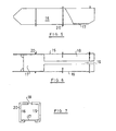
- the device proposed by the invention contains a rotating one Chain 1, which is guided around two parallel sprockets 2 and endless is driven.
- Figure 1 is only the left end of such a device shown.
- a large number of brackets 3 are attached to the chain 1 have a slide plate 4 at its free end.
- This facility will be in hereinafter referred to as slider.
- Slide 4 With chain 1 rotating, the Slide 4 along the lower run in a horizontal direction to the end the chain 1.
- the Bag station is designed so that with the help of an opener 11 each uppermost bag 10 of the stack 9 can be opened.
- This Opening movement of the opener 11 is not by the two cassettes 5, 6 hindered because they have a corresponding distance between them.
- the packaging cassette 5 with the already inserted therein Stack 7 moves in the conveying direction, that is to say from right to left in FIG. As a result, the packaging cassette 5 gets completely into the bag 10.
- the stack 7 of objects is also down to the bottom of the bag 10 pushed. This state is shown in Figure 3.
- the transfer cassette 6 is moved again in the conveying direction, at the same time the slide 4 is moved further.
- the slide 4 moves move at a greater speed than the transfer cassette 6. This means that the stack 7 in the longitudinal direction through the Transfer cassette 6 is pushed through.
- the transfer cassette 6 is moved to a position where you in Direction of conveyance front end between the welding jaws 13 one Capping station is pushed through. In this way, the stack 7 pushed through the welding jaws 13, and arrives there in a Intermediate station 14, where it is held on both sides and from above and below. When pushed through the welding jaws 13, the stack is in his Bag on a bottom of the transfer cassette 6 so that it is not attached any columns of the welding station get stuck. This state is in Figure 4 shown.
- the slide is then retracted by moving the boom upward around the deflection point 2.
- the transfer cassette 6 is now also moved against the conveying direction. As a result, it comes out of the space between the two welding jaws 13.
- the welding jaws 13 can now be moved towards each other to close the bag weld.
- the device proposed by the invention has the following advantages. By Reduction of malfunctions and forced shutdowns at high cycle rates and with multi-lane packaging processes, machine availability becomes elevated. Product control is improved, especially when loose Individual products cannot be inserted into a bag. The prepack has an improved look.
- the sliding distance of the products relative to the side walls is determined by the The movement of the product guide channels, namely the cassettes, is reduced. In particular, the transitions and abutting edges over which the product pushed, reduced. To further reduce the friction between An air cushion can be formed on the product and the walls of the cassettes become.
- the shape and effect of the cassettes will now be described with reference to the Figures 5 to 7 explained in more detail, with both cassettes constructed similarly are.
- the cassettes contain two side walls 15, 16 which act as flat walls are trained. They have a smooth surface at least on the inside Surface.
- the cassettes have a bottom 17, which is also smooth is trained. The bottom 17 can also be inserted and on the side Guides can be moved.
- the cassette Over a portion of its length, the cassette also includes an upper surface 18 which contains a narrow slot 19. This extends in the longitudinal direction of the cassette Extending slot 19 serves the boom 3 of the slide 4th pass.
- the cassette contains on the outside to increase the rigidity Reinforcing ribs 20, see also FIG. 7.
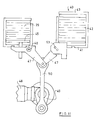
- Figure 8 shows a possibility of how the delivered vertically fluffy items can be converted to flat stacks.
- the device contains a pivoting device 21, which passes through a central one includes a servo motor rotatable shaft 22. There are four on shaft 22 Collection cassettes 23 rigidly attached, without this in the figure in detail is shown. The rigid attachment can also be designed so that have the cassettes 21 replaced. It is essential that the cassettes 23 (with elements 24, 26, 27, 25) can be rotated together with the shaft 22 can without changing their position in relation to the shaft and their Change the distance from the shaft.
- the cassettes have two side walls 24, 25 which are passed through a bottom 26 are interconnected.
- the top opposite the bottom 26 27 has a slot 28 which is perpendicular to the plane of the paper Has longitudinal extension.
- the cassettes 23 are open at the front and rear cuboid-shaped container.
- the cassette 23 on the right in FIG. 8 is in the filling position.
- the article 29, which are only hinted at, are from the pre-machine in vertical positioning delivered vertically grouped and in the cassette 23 inserted.
- the shaft 22 is then turned around by a servo motor Twisted 90 degrees. This brings the cassette into the upper position serves to push the stack of objects 29 out of the cassette.
- the longitudinal slot 28 is intended for pushing out. The pushing out is lied through the slider.
- a pressure wall 30 is arranged which is parallel to the Floor 26 runs.
- the pressure wall 30 is guided, namely in one such that it always remains parallel to the floor 26. That kind of Management is not shown in detail.
- the pressure wall 30 has one with it connected approach 31, for example for guiding the pressure wall 30 can serve.
- a roller 32 is attached to the projection 31, which in the groove 33rd a cam plate 34 engages.
- the cam and the groove 33 have the Oval shape.
- the cam 34 is arranged stationary, it does not rotate with the shaft 22. When the cassettes 23 are rotated with the help of the shaft 22, the rollers 32 slide in the groove 33 and thereby follow the Shape of the groove. This means that the pressure wall 30 when pivoting the right position in the upper opposition is moved radially outwards.
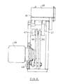
- Figure 9 shows the side view of the device of Figure 8.
- the top cassette 23 is in the emptying position, the individual parts being matched to one another in this way are that the pressure wall 30 now forming the floor is at the same height as a surface 35 is arranged, along which the stack 36 formed is displaced shall be.
- the insertion sides of the cassettes 23, on the right in FIG. 9, are somewhat extended to facilitate the insertion of the articles.
- the entire arrangement, including the servo motor 37, can be made using a Lifting unit 38 can be raised or lowered. So that the device can be adapted to different product heights (format adjustment).
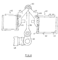
- Figures 10 to 12 show one Facility where the cartridges are given back and forth.
- Figure 10 are both cassettes 40 in their filling position, in which they are with vertical individual items are to be filled. How to figure 10 can be seen, both cassettes 40 are of different sizes. This facility can be used to close two packaging lines at the same time feed. Again a swivel device is provided around the cassettes 40 from the filling position shown in FIG. 10 to the one shown in FIG. 11 To pivot the emptying position.
- the cassettes which are also cuboid, contain one Bottom 41, two side walls 42 and a top 43.
- a longitudinal slot 44 is laterally instead of an edge between the side wall 42 and the top 43 educated.
- a pressure wall 45 is arranged parallel to the bottom 41, which in the same way parallel to itself within the cartridge 40 slidably is led.
- the cassettes are in one Inserted bracket with the help of an approach 46. So you can be removed.
- the bracket is in a two-armed lever 47 formed, which are given away around a fixed axis 48 can.
- a pivoting device is provided for pivoting contains a servo motor 48 as a drive.
- the servo motor 48 rotates an arm 49, whose axis of rotation extends perpendicular to the longitudinal axis of the servo motor 48.
- two articulated rods 50 are hinged, the other of which Ends 51 articulated, each with one of the two two-armed pivot levers 47 are connected.
- the two link rods 50 lie directly one behind the other so that they do not can be distinguished.
- the pressure wall 45 is by means of a lever 52 about an axis 53 other than the axis 48 of the pivot lever 47 is pivotally arranged.
- the Swiveling entrainment of the pressure wall 45 occurs only in that the Pressure wall 45 can only be moved linearly relative to the cassettes 40 can. Due to the articulated arrangement around another axis Displacement of the pressure wall relative to the bottom 41 of the cassettes 40, so that in this case too, Article 29 is compressed again. In the emptying position, the pressure wall 45 therefore faces away from the bottoms 41 space between the two cassettes while they are still open in the filling position the floors 41 rests.
- Figure 12 shows a side view of the arrangement of Figures 10 and 11. From the FIG. 12 shows that there are two articulated rods 50, one for each pivot lever 47. Similar to the previous one Embodiments can also the entire arrangement in height can be adjusted without this being shown in detail.
- the two Articulated rods 50 are arranged one behind the other so that they are in the Representation of both Figure 10 and Figure 11 overlap. Your Movement is derived from the same arm 49 so that it is the exact one Carry out the same movement, provided that both joint rods 50 are identical are trained.
Landscapes
- Engineering & Computer Science (AREA)
- Mechanical Engineering (AREA)
- Container Filling Or Packaging Operations (AREA)
- Auxiliary Devices For And Details Of Packaging Control (AREA)
- Supplying Of Containers To The Packaging Station (AREA)
Applications Claiming Priority (2)
| Application Number | Priority Date | Filing Date | Title |
|---|---|---|---|
| DE10100487 | 2001-01-04 | ||
| DE10100487 | 2001-01-04 |
Publications (3)
| Publication Number | Publication Date |
|---|---|
| EP1221410A2 true EP1221410A2 (fr) | 2002-07-10 |
| EP1221410A3 EP1221410A3 (fr) | 2002-09-04 |
| EP1221410B1 EP1221410B1 (fr) | 2004-04-28 |
Family
ID=7669941
Family Applications (1)
| Application Number | Title | Priority Date | Filing Date |
|---|---|---|---|
| EP01130784A Expired - Lifetime EP1221410B1 (fr) | 2001-01-04 | 2001-12-22 | Procédé et dispositif pour emballer des articles |
Country Status (6)
| Country | Link |
|---|---|
| US (1) | US6755008B2 (fr) |
| EP (1) | EP1221410B1 (fr) |
| JP (1) | JP4113708B2 (fr) |
| AT (1) | ATE265358T1 (fr) |
| DE (1) | DE50102117D1 (fr) |
| ES (1) | ES2220654T3 (fr) |
Cited By (5)
| Publication number | Priority date | Publication date | Assignee | Title |
|---|---|---|---|---|
| US7956623B2 (en) | 2007-02-16 | 2011-06-07 | Countlab, Inc | Container filling machine |
| US8006468B2 (en) | 2008-04-14 | 2011-08-30 | Countlab Inc. | Container filling machine having vibration trays |
| US8225925B2 (en) | 2008-12-02 | 2012-07-24 | Countlab Inc. | Discrete article spacing apparatus for vibration trays |
| CN113511354A (zh) * | 2021-05-25 | 2021-10-19 | 台山市宏盛自动化机械有限公司 | 一种床垫内胆机 |
| WO2023099067A1 (fr) * | 2021-11-30 | 2023-06-08 | Bucci Automations S.p.A. | Appareil d'emballage de groupes de produits |
Families Citing this family (17)
| Publication number | Priority date | Publication date | Assignee | Title |
|---|---|---|---|---|
| US20030095696A1 (en) * | 2001-09-14 | 2003-05-22 | Reeves Anthony P. | System, method and apparatus for small pulmonary nodule computer aided diagnosis from computed tomography scans |
| TWI496725B (zh) | 2009-01-20 | 2015-08-21 | Chamness Biodegradables Llc | 多層次容器 |
| US7891156B2 (en) * | 2009-03-24 | 2011-02-22 | Rethceif Enterprises, Llc | Packaging apparatus and method of packaging |
| EP2437988B1 (fr) * | 2009-06-05 | 2016-01-27 | Biosphere Holdings Corporation | Article d'emballage flexible à rigide et son procédé d'utilisation et de fabrication |
| US20130042943A1 (en) | 2011-08-18 | 2013-02-21 | Countlab, Inc. | Container filling machine |
| US9434487B2 (en) | 2011-09-30 | 2016-09-06 | Countlab, Inc | Container filling machine |
| DE102011055992A1 (de) * | 2011-12-02 | 2013-06-06 | Wincor Nixdorf International Gmbh | Vorrichtung und Verfahren zum Befüllen eines dünnwandigen Transportbehälters |
| ITBO20120619A1 (it) | 2012-11-09 | 2014-05-10 | Tissue Machinery Co Spa | Apparato e metodo di confezionamento di pannolini o altri oggetti sanitari morbidi piatti ripiegati. |
| US9718568B2 (en) * | 2013-06-06 | 2017-08-01 | Momentum Machines Company | Bagging system for packaging a foodstuff |
| JP2015093675A (ja) * | 2013-11-08 | 2015-05-18 | オリオン機械工業株式会社 | 包装機の圧縮装置 |
| BR102014030315B1 (pt) * | 2014-12-04 | 2021-09-08 | Ball Beverage Can South America S/A | Processo de embalagem de um conjunto de tampas empilhadas e dispositivo de embalagem para conjuntos de tampas empilhadas |
| WO2017053396A1 (fr) | 2015-09-21 | 2017-03-30 | AMI Investments, LLC | Surveillance à distance de système de distribution d'eau |
| US11988656B2 (en) | 2015-09-21 | 2024-05-21 | Mcwane, Inc. | Remote monitoring of water distribution system |
| CN115231044B (zh) * | 2021-04-23 | 2024-04-12 | 湖南大用自动化科技有限公司 | 进料装置及物料打包机 |
| DE102022110258A1 (de) * | 2022-04-27 | 2023-11-02 | Krones Aktiengesellschaft | Magazineinheit, Verpackungsvorrichtung und Verfahren zum Zusammenfassen von Artikelzusammenstellungen |
| US12564748B2 (en) | 2022-08-05 | 2026-03-03 | Clow Valve Co. division of McWane, Inc. | Remote monitoring of water distribution system |
| TWM646389U (zh) * | 2023-05-11 | 2023-09-21 | 林源裕 | 紙袋自動包裝機 |
Citations (1)
| Publication number | Priority date | Publication date | Assignee | Title |
|---|---|---|---|---|
| EP0816235A1 (fr) | 1996-07-03 | 1998-01-07 | Optima-Maschinenfabrik Dr. Bühler GmbH & Co. | Dispositif d'emballage d'articles |
Family Cites Families (15)
| Publication number | Priority date | Publication date | Assignee | Title |
|---|---|---|---|---|
| US3228171A (en) * | 1962-10-05 | 1966-01-11 | Fmc Corp | Packaging machine |
| US3508379A (en) * | 1968-08-05 | 1970-04-28 | Formo Alvin C | Bagging machine |
| DE6800717U (de) * | 1968-10-03 | 1969-04-10 | Bauer Eberhard | Maschine zum verpacken von insbesondere schnittbrotpaketen in beutel. |
| US3619976A (en) * | 1970-01-27 | 1971-11-16 | William C Kerker | Bag bundling machine |
| US3810344A (en) * | 1972-03-29 | 1974-05-14 | Procter & Gamble | Machine for packaging flexible articles |
| US3903675A (en) * | 1974-11-21 | 1975-09-09 | Clayton Specialties Inc | Bagging apparatus |
| GB1540218A (en) * | 1975-03-20 | 1979-02-07 | Southalls Ltd | Packaging machines |
| US4037388A (en) * | 1976-06-01 | 1977-07-26 | United Bakery Equipment Company, Inc. | Bag supply system for bagging machine |
| DE2739329A1 (de) * | 1977-09-01 | 1979-03-15 | Lucke Apparatebau | Vorrichtung zum herstellen einer durch eine schweissnaht verschlossenen verpackung fuer garnknaeuel o.dgl. |
| US4492070A (en) * | 1979-04-09 | 1985-01-08 | Morse Hugh B | Case loading apparatus and method |
| US4242854A (en) * | 1979-07-23 | 1981-01-06 | Kimberly-Clark Corporation | Automatic bag loader |
| US4756141A (en) | 1987-04-22 | 1988-07-12 | Curt G. Joa, Inc. | Apparatus for rotating and compressing a stack of pads |
| US5056300A (en) * | 1988-12-06 | 1991-10-15 | Kabushiki Kaisha Daisei Kikai | Bagging apparatus, and bag opening device for article-bagging |
| US5228275A (en) * | 1992-05-29 | 1993-07-20 | Formost Packaging Machines, Inc. | Process and apparatus for packaging limp articles |
| JP2001237706A (ja) | 2000-02-23 | 2001-08-31 | Hitachi Ltd | Δς型ad変換器 |
-
2001
- 2001-12-22 AT AT01130784T patent/ATE265358T1/de not_active IP Right Cessation
- 2001-12-22 DE DE50102117T patent/DE50102117D1/de not_active Expired - Lifetime
- 2001-12-22 ES ES01130784T patent/ES2220654T3/es not_active Expired - Lifetime
- 2001-12-22 EP EP01130784A patent/EP1221410B1/fr not_active Expired - Lifetime
- 2001-12-26 JP JP2001394741A patent/JP4113708B2/ja not_active Expired - Lifetime
-
2002
- 2002-01-03 US US10/038,778 patent/US6755008B2/en not_active Expired - Lifetime
Patent Citations (1)
| Publication number | Priority date | Publication date | Assignee | Title |
|---|---|---|---|---|
| EP0816235A1 (fr) | 1996-07-03 | 1998-01-07 | Optima-Maschinenfabrik Dr. Bühler GmbH & Co. | Dispositif d'emballage d'articles |
Cited By (5)
| Publication number | Priority date | Publication date | Assignee | Title |
|---|---|---|---|---|
| US7956623B2 (en) | 2007-02-16 | 2011-06-07 | Countlab, Inc | Container filling machine |
| US8006468B2 (en) | 2008-04-14 | 2011-08-30 | Countlab Inc. | Container filling machine having vibration trays |
| US8225925B2 (en) | 2008-12-02 | 2012-07-24 | Countlab Inc. | Discrete article spacing apparatus for vibration trays |
| CN113511354A (zh) * | 2021-05-25 | 2021-10-19 | 台山市宏盛自动化机械有限公司 | 一种床垫内胆机 |
| WO2023099067A1 (fr) * | 2021-11-30 | 2023-06-08 | Bucci Automations S.p.A. | Appareil d'emballage de groupes de produits |
Also Published As
| Publication number | Publication date |
|---|---|
| US20020124533A1 (en) | 2002-09-12 |
| DE50102117D1 (de) | 2004-06-03 |
| ATE265358T1 (de) | 2004-05-15 |
| EP1221410B1 (fr) | 2004-04-28 |
| US6755008B2 (en) | 2004-06-29 |
| ES2220654T3 (es) | 2004-12-16 |
| JP4113708B2 (ja) | 2008-07-09 |
| JP2002249103A (ja) | 2002-09-03 |
| EP1221410A3 (fr) | 2002-09-04 |
Similar Documents
| Publication | Publication Date | Title |
|---|---|---|
| EP1221410B1 (fr) | Procédé et dispositif pour emballer des articles | |
| DE2124984C3 (de) | Vorrichtung zum automatischen Verpacken von jeweils mehreren Behältern in einen Kasten | |
| EP2439142B1 (fr) | Dispositif de transport et d'introduction de produits d'emballage | |
| DE102007006133A1 (de) | Entleermagazin und Verfahren zum Entleeren von mit stabförmigen Produkten gefüllten Schachtschragen | |
| DE69805083T2 (de) | Vorrichtung und verfahren zum versiegeln der offenen enden eines stromes von verpackungen | |
| EP0257186B1 (fr) | Dispositif de formage et de remplissage d'emballages en carton | |
| DE3935457A1 (de) | Vorrichtung zum verpacken eines gutes, insbesondere von windeln, in zusammengepresstem zustand | |
| DE60201425T2 (de) | Verfahren und vorrichtung zum schliessen einer schachtel durch falten einer lateralen schliessklappe | |
| EP3372513B1 (fr) | Dispositif de manipulation d'articles et procédé d'échange d'au moins un module de transport et d'au moins un dispositif de travail dudit module | |
| EP0706488B1 (fr) | Vehicule de collecte des dechets | |
| DE3221862A1 (de) | Vorrichtung zum zufuehren von behaeltern oder schachteln in einer auf zwei gegenueberliegenden seiten durchgehend geoeffneten form | |
| DE2500392A1 (de) | Verpackungsmaschine | |
| CH658632A5 (de) | Verfahren zum abpacken von schlauchbeuteln in schachteln, sowie vorrichtung zur durchfuehrung des verfahrens. | |
| DE2423885C2 (de) | Vorrichtung zum Übergeben von Stapeln aus blattförmigen Materialzuschnitten | |
| DE19626665A1 (de) | Vorrichtung zum Verpacken von Gegenständen | |
| EP2108271B9 (fr) | Cartouche de vidage et procédé de vidage de combles de puits remplis de produits en forme de tiges | |
| DE2163588A1 (de) | Schachte !fülleinrichtung | |
| DE2608130A1 (de) | Kartonherstellungsvorrichtung | |
| DE3106300A1 (de) | Sammelverpackungsmaschine | |
| DE19822998C2 (de) | Vorrichtung zum Einbringen von gestapelten Kuverts in einen Transportkasten | |
| DE3815557A1 (de) | Verbundmaschine zum automatischen verpacken von packgut in faltschachteln | |
| DE19739533A1 (de) | Verpackungsvorrichtung | |
| DE69311322T2 (de) | Beschickungsvorrichtung zur verwendung in kartoniereinrichtungen | |
| DE4406089A1 (de) | Verfahren und Vorrichtung zum Abfüllen von Tabletten oder dergleichen in Tablettenröhrchen | |
| DE2950553A1 (de) | Maschine zum herstellen und fuellen von saecken |
Legal Events
| Date | Code | Title | Description |
|---|---|---|---|
| PUAI | Public reference made under article 153(3) epc to a published international application that has entered the european phase |
Free format text: ORIGINAL CODE: 0009012 |
|
| AK | Designated contracting states |
Kind code of ref document: A2 Designated state(s): AT BE CH CY DE DK ES FI FR GB GR IE IT LI LU MC NL PT SE TR |
|
| AX | Request for extension of the european patent |
Free format text: AL;LT;LV;MK;RO;SI |
|
| PUAL | Search report despatched |
Free format text: ORIGINAL CODE: 0009013 |
|
| AK | Designated contracting states |
Kind code of ref document: A3 Designated state(s): AT BE CH CY DE DK ES FI FR GB GR IE IT LI LU MC NL PT SE TR |
|
| AX | Request for extension of the european patent |
Free format text: AL;LT;LV;MK;RO;SI |
|
| 17P | Request for examination filed |
Effective date: 20030118 |
|
| 17Q | First examination report despatched |
Effective date: 20030326 |
|
| AKX | Designation fees paid |
Designated state(s): AT BE CH CY DE DK ES FI FR GB GR IE IT LI LU MC NL PT SE TR |
|
| GRAP | Despatch of communication of intention to grant a patent |
Free format text: ORIGINAL CODE: EPIDOSNIGR1 |
|
| RIN1 | Information on inventor provided before grant (corrected) |
Inventor name: SCHMETZER, DIETMAR Inventor name: GRIESSMAYR, KLAUS |
|
| GRAS | Grant fee paid |
Free format text: ORIGINAL CODE: EPIDOSNIGR3 |
|
| GRAA | (expected) grant |
Free format text: ORIGINAL CODE: 0009210 |
|
| AK | Designated contracting states |
Kind code of ref document: B1 Designated state(s): AT BE CH CY DE DK ES FI FR GB GR IE IT LI LU MC NL PT SE TR |
|
| PG25 | Lapsed in a contracting state [announced via postgrant information from national office to epo] |
Ref country code: CY Free format text: LAPSE BECAUSE OF FAILURE TO SUBMIT A TRANSLATION OF THE DESCRIPTION OR TO PAY THE FEE WITHIN THE PRESCRIBED TIME-LIMIT Effective date: 20040428 Ref country code: TR Free format text: LAPSE BECAUSE OF FAILURE TO SUBMIT A TRANSLATION OF THE DESCRIPTION OR TO PAY THE FEE WITHIN THE PRESCRIBED TIME-LIMIT Effective date: 20040428 Ref country code: IE Free format text: LAPSE BECAUSE OF FAILURE TO SUBMIT A TRANSLATION OF THE DESCRIPTION OR TO PAY THE FEE WITHIN THE PRESCRIBED TIME-LIMIT Effective date: 20040428 Ref country code: NL Free format text: LAPSE BECAUSE OF FAILURE TO SUBMIT A TRANSLATION OF THE DESCRIPTION OR TO PAY THE FEE WITHIN THE PRESCRIBED TIME-LIMIT Effective date: 20040428 Ref country code: FI Free format text: LAPSE BECAUSE OF FAILURE TO SUBMIT A TRANSLATION OF THE DESCRIPTION OR TO PAY THE FEE WITHIN THE PRESCRIBED TIME-LIMIT Effective date: 20040428 |
|
| REG | Reference to a national code |
Ref country code: GB Ref legal event code: FG4D Free format text: NOT ENGLISH |
|
| REG | Reference to a national code |
Ref country code: CH Ref legal event code: EP |
|
| REG | Reference to a national code |
Ref country code: SE Ref legal event code: TRGR |
|
| REG | Reference to a national code |
Ref country code: IE Ref legal event code: FG4D Free format text: GERMAN |
|
| REF | Corresponds to: |
Ref document number: 50102117 Country of ref document: DE Date of ref document: 20040603 Kind code of ref document: P |
|
| GBT | Gb: translation of ep patent filed (gb section 77(6)(a)/1977) |
Effective date: 20040614 |
|
| PG25 | Lapsed in a contracting state [announced via postgrant information from national office to epo] |
Ref country code: GR Free format text: LAPSE BECAUSE OF FAILURE TO SUBMIT A TRANSLATION OF THE DESCRIPTION OR TO PAY THE FEE WITHIN THE PRESCRIBED TIME-LIMIT Effective date: 20040728 Ref country code: DK Free format text: LAPSE BECAUSE OF FAILURE TO SUBMIT A TRANSLATION OF THE DESCRIPTION OR TO PAY THE FEE WITHIN THE PRESCRIBED TIME-LIMIT Effective date: 20040728 |
|
| NLV1 | Nl: lapsed or annulled due to failure to fulfill the requirements of art. 29p and 29m of the patents act | ||
| REG | Reference to a national code |
Ref country code: IE Ref legal event code: FD4D |
|
| REG | Reference to a national code |
Ref country code: ES Ref legal event code: FG2A Ref document number: 2220654 Country of ref document: ES Kind code of ref document: T3 |
|
| PG25 | Lapsed in a contracting state [announced via postgrant information from national office to epo] |
Ref country code: AT Free format text: LAPSE BECAUSE OF NON-PAYMENT OF DUE FEES Effective date: 20041222 Ref country code: LU Free format text: LAPSE BECAUSE OF NON-PAYMENT OF DUE FEES Effective date: 20041222 |
|
| PG25 | Lapsed in a contracting state [announced via postgrant information from national office to epo] |
Ref country code: MC Free format text: LAPSE BECAUSE OF NON-PAYMENT OF DUE FEES Effective date: 20041231 |
|
| ET | Fr: translation filed | ||
| PLBE | No opposition filed within time limit |
Free format text: ORIGINAL CODE: 0009261 |
|
| STAA | Information on the status of an ep patent application or granted ep patent |
Free format text: STATUS: NO OPPOSITION FILED WITHIN TIME LIMIT |
|
| 26N | No opposition filed |
Effective date: 20050131 |
|
| PG25 | Lapsed in a contracting state [announced via postgrant information from national office to epo] |
Ref country code: CH Free format text: LAPSE BECAUSE OF NON-PAYMENT OF DUE FEES Effective date: 20051231 Ref country code: LI Free format text: LAPSE BECAUSE OF NON-PAYMENT OF DUE FEES Effective date: 20051231 |
|
| REG | Reference to a national code |
Ref country code: CH Ref legal event code: PL |
|
| PG25 | Lapsed in a contracting state [announced via postgrant information from national office to epo] |
Ref country code: PT Free format text: LAPSE BECAUSE OF NON-PAYMENT OF DUE FEES Effective date: 20040928 |
|
| REG | Reference to a national code |
Ref country code: FR Ref legal event code: PLFP Year of fee payment: 15 |
|
| REG | Reference to a national code |
Ref country code: DE Ref legal event code: R082 Ref document number: 50102117 Country of ref document: DE Representative=s name: PATENTANWAELTE RUFF, WILHELM, BEIER, DAUSTER &, DE Ref country code: DE Ref legal event code: R081 Ref document number: 50102117 Country of ref document: DE Owner name: OPTIMA NONWOVENS GMBH, DE Free format text: FORMER OWNER: OPTIMA FILLING AND PACKAGING MACHINES GMBH, 74523 SCHWAEBISCH HALL, DE |
|
| REG | Reference to a national code |
Ref country code: FR Ref legal event code: PLFP Year of fee payment: 16 |
|
| REG | Reference to a national code |
Ref country code: FR Ref legal event code: PLFP Year of fee payment: 17 |
|
| PGFP | Annual fee paid to national office [announced via postgrant information from national office to epo] |
Ref country code: FR Payment date: 20201218 Year of fee payment: 20 Ref country code: GB Payment date: 20201222 Year of fee payment: 20 Ref country code: SE Payment date: 20201221 Year of fee payment: 20 |
|
| PGFP | Annual fee paid to national office [announced via postgrant information from national office to epo] |
Ref country code: BE Payment date: 20201217 Year of fee payment: 20 |
|
| PGFP | Annual fee paid to national office [announced via postgrant information from national office to epo] |
Ref country code: DE Payment date: 20201217 Year of fee payment: 20 Ref country code: ES Payment date: 20210122 Year of fee payment: 20 |
|
| PGFP | Annual fee paid to national office [announced via postgrant information from national office to epo] |
Ref country code: IT Payment date: 20201230 Year of fee payment: 20 |
|
| REG | Reference to a national code |
Ref country code: DE Ref legal event code: R071 Ref document number: 50102117 Country of ref document: DE |
|
| REG | Reference to a national code |
Ref country code: GB Ref legal event code: PE20 Expiry date: 20211221 |
|
| REG | Reference to a national code |
Ref country code: SE Ref legal event code: EUG |
|
| PG25 | Lapsed in a contracting state [announced via postgrant information from national office to epo] |
Ref country code: GB Free format text: LAPSE BECAUSE OF EXPIRATION OF PROTECTION Effective date: 20211221 |
|
| REG | Reference to a national code |
Ref country code: BE Ref legal event code: MK Effective date: 20211222 |
|
| REG | Reference to a national code |
Ref country code: ES Ref legal event code: FD2A Effective date: 20220405 |
|
| PG25 | Lapsed in a contracting state [announced via postgrant information from national office to epo] |
Ref country code: ES Free format text: LAPSE BECAUSE OF EXPIRATION OF PROTECTION Effective date: 20211223 |