EP1221431A1 - Pâte pour la formation de nervures céramiques, méthode de production et méthode de formation de nervures utilisant cette pâte - Google Patents
Pâte pour la formation de nervures céramiques, méthode de production et méthode de formation de nervures utilisant cette pâte Download PDFInfo
- Publication number
- EP1221431A1 EP1221431A1 EP02000163A EP02000163A EP1221431A1 EP 1221431 A1 EP1221431 A1 EP 1221431A1 EP 02000163 A EP02000163 A EP 02000163A EP 02000163 A EP02000163 A EP 02000163A EP 1221431 A1 EP1221431 A1 EP 1221431A1
- Authority
- EP
- European Patent Office
- Prior art keywords
- boiling point
- paste
- solvents
- ribs
- low boiling
- Prior art date
- Legal status (The legal status is an assumption and is not a legal conclusion. Google has not performed a legal analysis and makes no representation as to the accuracy of the status listed.)
- Withdrawn
Links
- 239000000919 ceramic Substances 0.000 title claims description 56
- 238000000034 method Methods 0.000 title claims description 35
- 238000004519 manufacturing process Methods 0.000 title claims description 11
- 239000002904 solvent Substances 0.000 claims abstract description 185
- 238000009835 boiling Methods 0.000 claims abstract description 166
- 239000000843 powder Substances 0.000 claims abstract description 39
- 239000011521 glass Substances 0.000 claims abstract description 35
- 239000011347 resin Substances 0.000 claims abstract description 22
- 229920005989 resin Polymers 0.000 claims abstract description 22
- 239000011812 mixed powder Substances 0.000 claims abstract description 17
- 239000002241 glass-ceramic Substances 0.000 claims abstract description 15
- 239000000758 substrate Substances 0.000 claims description 76
- RTZKZFJDLAIYFH-UHFFFAOYSA-N Diethyl ether Chemical compound CCOCC RTZKZFJDLAIYFH-UHFFFAOYSA-N 0.000 claims description 21
- 239000000203 mixture Substances 0.000 claims description 15
- 229930195733 hydrocarbon Natural products 0.000 claims description 12
- 150000002430 hydrocarbons Chemical class 0.000 claims description 12
- 238000000576 coating method Methods 0.000 claims description 11
- 239000011248 coating agent Substances 0.000 claims description 10
- 239000002270 dispersing agent Substances 0.000 claims description 8
- 238000001035 drying Methods 0.000 claims description 8
- 239000004014 plasticizer Substances 0.000 claims description 8
- 239000004215 Carbon black (E152) Substances 0.000 claims description 7
- JBTWLSYIZRCDFO-UHFFFAOYSA-N ethyl methyl carbonate Chemical compound CCOC(=O)OC JBTWLSYIZRCDFO-UHFFFAOYSA-N 0.000 claims description 5
- 238000004898 kneading Methods 0.000 claims description 4
- 239000004210 ether based solvent Substances 0.000 claims 2
- 230000032683 aging Effects 0.000 abstract description 7
- 229920003023 plastic Polymers 0.000 abstract description 7
- 239000004033 plastic Substances 0.000 abstract description 7
- 230000000052 comparative effect Effects 0.000 description 20
- LRHPLDYGYMQRHN-UHFFFAOYSA-N N-Butanol Chemical compound CCCCO LRHPLDYGYMQRHN-UHFFFAOYSA-N 0.000 description 9
- JOLQKTGDSGKSKJ-UHFFFAOYSA-N 1-ethoxypropan-2-ol Chemical compound CCOCC(C)O JOLQKTGDSGKSKJ-UHFFFAOYSA-N 0.000 description 8
- -1 alcohol ester Chemical class 0.000 description 8
- 239000006185 dispersion Substances 0.000 description 8
- 239000002245 particle Substances 0.000 description 7
- RDOXTESZEPMUJZ-UHFFFAOYSA-N anisole Chemical compound COC1=CC=CC=C1 RDOXTESZEPMUJZ-UHFFFAOYSA-N 0.000 description 6
- IIEWJVIFRVWJOD-UHFFFAOYSA-N ethylcyclohexane Chemical compound CCC1CCCCC1 IIEWJVIFRVWJOD-UHFFFAOYSA-N 0.000 description 6
- MLFHJEHSLIIPHL-UHFFFAOYSA-N isoamyl acetate Chemical compound CC(C)CCOC(C)=O MLFHJEHSLIIPHL-UHFFFAOYSA-N 0.000 description 6
- BKIMMITUMNQMOS-UHFFFAOYSA-N nonane Chemical compound CCCCCCCCC BKIMMITUMNQMOS-UHFFFAOYSA-N 0.000 description 6
- 239000001856 Ethyl cellulose Substances 0.000 description 5
- ZZSNKZQZMQGXPY-UHFFFAOYSA-N Ethyl cellulose Chemical compound CCOCC1OC(OC)C(OCC)C(OCC)C1OC1C(O)C(O)C(OC)C(CO)O1 ZZSNKZQZMQGXPY-UHFFFAOYSA-N 0.000 description 5
- 150000002170 ethers Chemical class 0.000 description 5
- 235000019325 ethyl cellulose Nutrition 0.000 description 5
- 229920001249 ethyl cellulose Polymers 0.000 description 5
- 230000000149 penetrating effect Effects 0.000 description 5
- 238000007639 printing Methods 0.000 description 5
- WVYWICLMDOOCFB-UHFFFAOYSA-N 4-methyl-2-pentanol Chemical compound CC(C)CC(C)O WVYWICLMDOOCFB-UHFFFAOYSA-N 0.000 description 4
- PEDCQBHIVMGVHV-UHFFFAOYSA-N Glycerine Chemical compound OCC(O)CO PEDCQBHIVMGVHV-UHFFFAOYSA-N 0.000 description 4
- CTQNGGLPUBDAKN-UHFFFAOYSA-N O-Xylene Chemical group CC1=CC=CC=C1C CTQNGGLPUBDAKN-UHFFFAOYSA-N 0.000 description 4
- VYPSYNLAJGMNEJ-UHFFFAOYSA-N Silicium dioxide Chemical compound O=[Si]=O VYPSYNLAJGMNEJ-UHFFFAOYSA-N 0.000 description 4
- 230000015572 biosynthetic process Effects 0.000 description 4
- 238000007650 screen-printing Methods 0.000 description 4
- 230000008016 vaporization Effects 0.000 description 4
- PBKONEOXTCPAFI-UHFFFAOYSA-N 1,2,4-trichlorobenzene Chemical compound ClC1=CC=C(Cl)C(Cl)=C1 PBKONEOXTCPAFI-UHFFFAOYSA-N 0.000 description 3
- DURPTKYDGMDSBL-UHFFFAOYSA-N 1-butoxybutane Chemical compound CCCCOCCCC DURPTKYDGMDSBL-UHFFFAOYSA-N 0.000 description 3
- KWKAKUADMBZCLK-UHFFFAOYSA-N 1-octene Chemical compound CCCCCCC=C KWKAKUADMBZCLK-UHFFFAOYSA-N 0.000 description 3
- QPRQEDXDYOZYLA-UHFFFAOYSA-N 2-methylbutan-1-ol Chemical compound CCC(C)CO QPRQEDXDYOZYLA-UHFFFAOYSA-N 0.000 description 3
- WVDDGKGOMKODPV-UHFFFAOYSA-N Benzyl alcohol Chemical compound OCC1=CC=CC=C1 WVDDGKGOMKODPV-UHFFFAOYSA-N 0.000 description 3
- OIFBSDVPJOWBCH-UHFFFAOYSA-N Diethyl carbonate Chemical compound CCOC(=O)OCC OIFBSDVPJOWBCH-UHFFFAOYSA-N 0.000 description 3
- ZMXDDKWLCZADIW-UHFFFAOYSA-N N,N-Dimethylformamide Chemical compound CN(C)C=O ZMXDDKWLCZADIW-UHFFFAOYSA-N 0.000 description 3
- SJRJJKPEHAURKC-UHFFFAOYSA-N N-Methylmorpholine Chemical compound CN1CCOCC1 SJRJJKPEHAURKC-UHFFFAOYSA-N 0.000 description 3
- 150000001298 alcohols Chemical class 0.000 description 3
- 150000001875 compounds Chemical class 0.000 description 3
- MTHSVFCYNBDYFN-UHFFFAOYSA-N diethylene glycol Chemical compound OCCOCCO MTHSVFCYNBDYFN-UHFFFAOYSA-N 0.000 description 3
- SBZXBUIDTXKZTM-UHFFFAOYSA-N diglyme Chemical compound COCCOCCOC SBZXBUIDTXKZTM-UHFFFAOYSA-N 0.000 description 3
- 150000002148 esters Chemical class 0.000 description 3
- 239000000945 filler Substances 0.000 description 3
- 125000000524 functional group Chemical group 0.000 description 3
- XPFVYQJUAUNWIW-UHFFFAOYSA-N furfuryl alcohol Chemical compound OCC1=CC=CO1 XPFVYQJUAUNWIW-UHFFFAOYSA-N 0.000 description 3
- UZKWTJUDCOPSNM-UHFFFAOYSA-N methoxybenzene Substances CCCCOC=C UZKWTJUDCOPSNM-UHFFFAOYSA-N 0.000 description 3
- 238000007665 sagging Methods 0.000 description 3
- CXWXQJXEFPUFDZ-UHFFFAOYSA-N tetralin Chemical compound C1=CC=C2CCCCC2=C1 CXWXQJXEFPUFDZ-UHFFFAOYSA-N 0.000 description 3
- PUPZLCDOIYMWBV-UHFFFAOYSA-N (+/-)-1,3-Butanediol Chemical compound CC(O)CCO PUPZLCDOIYMWBV-UHFFFAOYSA-N 0.000 description 2
- GRWFGVWFFZKLTI-IUCAKERBSA-N (-)-α-pinene Chemical compound CC1=CC[C@@H]2C(C)(C)[C@H]1C2 GRWFGVWFFZKLTI-IUCAKERBSA-N 0.000 description 2
- QPFMBZIOSGYJDE-UHFFFAOYSA-N 1,1,2,2-tetrachloroethane Chemical compound ClC(Cl)C(Cl)Cl QPFMBZIOSGYJDE-UHFFFAOYSA-N 0.000 description 2
- CFXQEHVMCRXUSD-UHFFFAOYSA-N 1,2,3-Trichloropropane Chemical compound ClCC(Cl)CCl CFXQEHVMCRXUSD-UHFFFAOYSA-N 0.000 description 2
- AUHZEENZYGFFBQ-UHFFFAOYSA-N 1,3,5-trimethylbenzene Chemical compound CC1=CC(C)=CC(C)=C1 AUHZEENZYGFFBQ-UHFFFAOYSA-N 0.000 description 2
- CHLICZRVGGXEOD-UHFFFAOYSA-N 1-Methoxy-4-methylbenzene Chemical compound COC1=CC=C(C)C=C1 CHLICZRVGGXEOD-UHFFFAOYSA-N 0.000 description 2
- YYTSGNJTASLUOY-UHFFFAOYSA-N 1-chloropropan-2-ol Chemical compound CC(O)CCl YYTSGNJTASLUOY-UHFFFAOYSA-N 0.000 description 2
- AFFLGGQVNFXPEV-UHFFFAOYSA-N 1-decene Chemical compound CCCCCCCCC=C AFFLGGQVNFXPEV-UHFFFAOYSA-N 0.000 description 2
- BBMCTIGTTCKYKF-UHFFFAOYSA-N 1-heptanol Chemical compound CCCCCCCO BBMCTIGTTCKYKF-UHFFFAOYSA-N 0.000 description 2
- ARXJGSRGQADJSQ-UHFFFAOYSA-N 1-methoxypropan-2-ol Chemical compound COCC(C)O ARXJGSRGQADJSQ-UHFFFAOYSA-N 0.000 description 2
- JRZJOMJEPLMPRA-UHFFFAOYSA-N 1-nonene Chemical compound CCCCCCCC=C JRZJOMJEPLMPRA-UHFFFAOYSA-N 0.000 description 2
- JYYNAJVZFGKDEQ-UHFFFAOYSA-N 2,4-Dimethylpyridine Chemical compound CC1=CC=NC(C)=C1 JYYNAJVZFGKDEQ-UHFFFAOYSA-N 0.000 description 2
- XWKFPIODWVPXLX-UHFFFAOYSA-N 2,5-dimethylpyridine Chemical compound CC1=CC=C(C)N=C1 XWKFPIODWVPXLX-UHFFFAOYSA-N 0.000 description 2
- HZAXFHJVJLSVMW-UHFFFAOYSA-N 2-Aminoethan-1-ol Chemical compound NCCO HZAXFHJVJLSVMW-UHFFFAOYSA-N 0.000 description 2
- RXGUIWHIADMCFC-UHFFFAOYSA-N 2-Methylpropyl 2-methylpropionate Chemical compound CC(C)COC(=O)C(C)C RXGUIWHIADMCFC-UHFFFAOYSA-N 0.000 description 2
- QQZOPKMRPOGIEB-UHFFFAOYSA-N 2-Oxohexane Chemical compound CCCCC(C)=O QQZOPKMRPOGIEB-UHFFFAOYSA-N 0.000 description 2
- CETWDUZRCINIHU-UHFFFAOYSA-N 2-heptanol Chemical compound CCCCCC(C)O CETWDUZRCINIHU-UHFFFAOYSA-N 0.000 description 2
- XLLIQLLCWZCATF-UHFFFAOYSA-N 2-methoxyethyl acetate Chemical compound COCCOC(C)=O XLLIQLLCWZCATF-UHFFFAOYSA-N 0.000 description 2
- PFNHSEQQEPMLNI-UHFFFAOYSA-N 2-methyl-1-pentanol Chemical compound CCCC(C)CO PFNHSEQQEPMLNI-UHFFFAOYSA-N 0.000 description 2
- CRWNQZTZTZWPOF-UHFFFAOYSA-N 2-methyl-4-phenylpyridine Chemical compound C1=NC(C)=CC(C=2C=CC=CC=2)=C1 CRWNQZTZTZWPOF-UHFFFAOYSA-N 0.000 description 2
- MXLMTQWGSQIYOW-UHFFFAOYSA-N 3-methyl-2-butanol Chemical compound CC(C)C(C)O MXLMTQWGSQIYOW-UHFFFAOYSA-N 0.000 description 2
- JJYPMNFTHPTTDI-UHFFFAOYSA-N 3-methylaniline Chemical compound CC1=CC=CC(N)=C1 JJYPMNFTHPTTDI-UHFFFAOYSA-N 0.000 description 2
- HCFAJYNVAYBARA-UHFFFAOYSA-N 4-heptanone Chemical compound CCCC(=O)CCC HCFAJYNVAYBARA-UHFFFAOYSA-N 0.000 description 2
- FKNQCJSGGFJEIZ-UHFFFAOYSA-N 4-methylpyridine Chemical compound CC1=CC=NC=C1 FKNQCJSGGFJEIZ-UHFFFAOYSA-N 0.000 description 2
- KWOLFJPFCHCOCG-UHFFFAOYSA-N Acetophenone Chemical compound CC(=O)C1=CC=CC=C1 KWOLFJPFCHCOCG-UHFFFAOYSA-N 0.000 description 2
- YNQLUTRBYVCPMQ-UHFFFAOYSA-N Ethylbenzene Chemical compound CCC1=CC=CC=C1 YNQLUTRBYVCPMQ-UHFFFAOYSA-N 0.000 description 2
- ZHNUHDYFZUAESO-UHFFFAOYSA-N Formamide Chemical compound NC=O ZHNUHDYFZUAESO-UHFFFAOYSA-N 0.000 description 2
- RZKSECIXORKHQS-UHFFFAOYSA-N Heptan-3-ol Chemical compound CCCCC(O)CC RZKSECIXORKHQS-UHFFFAOYSA-N 0.000 description 2
- YNAVUWVOSKDBBP-UHFFFAOYSA-N Morpholine Chemical compound C1COCCN1 YNAVUWVOSKDBBP-UHFFFAOYSA-N 0.000 description 2
- AMQJEAYHLZJPGS-UHFFFAOYSA-N N-Pentanol Chemical compound CCCCCO AMQJEAYHLZJPGS-UHFFFAOYSA-N 0.000 description 2
- JKRZOJADNVOXPM-UHFFFAOYSA-N Oxalic acid dibutyl ester Chemical compound CCCCOC(=O)C(=O)OCCCC JKRZOJADNVOXPM-UHFFFAOYSA-N 0.000 description 2
- 229910019142 PO4 Inorganic materials 0.000 description 2
- URLKBWYHVLBVBO-UHFFFAOYSA-N Para-Xylene Chemical group CC1=CC=C(C)C=C1 URLKBWYHVLBVBO-UHFFFAOYSA-N 0.000 description 2
- PWATWSYOIIXYMA-UHFFFAOYSA-N Pentylbenzene Chemical compound CCCCCC1=CC=CC=C1 PWATWSYOIIXYMA-UHFFFAOYSA-N 0.000 description 2
- KAESVJOAVNADME-UHFFFAOYSA-N Pyrrole Chemical compound C=1C=CNC=1 KAESVJOAVNADME-UHFFFAOYSA-N 0.000 description 2
- SMWDFEZZVXVKRB-UHFFFAOYSA-N Quinoline Chemical compound N1=CC=CC2=CC=CC=C21 SMWDFEZZVXVKRB-UHFFFAOYSA-N 0.000 description 2
- PPBRXRYQALVLMV-UHFFFAOYSA-N Styrene Chemical compound C=CC1=CC=CC=C1 PPBRXRYQALVLMV-UHFFFAOYSA-N 0.000 description 2
- GWEVSGVZZGPLCZ-UHFFFAOYSA-N Titan oxide Chemical compound O=[Ti]=O GWEVSGVZZGPLCZ-UHFFFAOYSA-N 0.000 description 2
- XAGFODPZIPBFFR-UHFFFAOYSA-N aluminium Chemical compound [Al] XAGFODPZIPBFFR-UHFFFAOYSA-N 0.000 description 2
- QUKGYYKBILRGFE-UHFFFAOYSA-N benzyl acetate Chemical compound CC(=O)OCC1=CC=CC=C1 QUKGYYKBILRGFE-UHFFFAOYSA-N 0.000 description 2
- BJQHLKABXJIVAM-UHFFFAOYSA-N bis(2-ethylhexyl) phthalate Chemical compound CCCCC(CC)COC(=O)C1=CC=CC=C1C(=O)OCC(CC)CCCC BJQHLKABXJIVAM-UHFFFAOYSA-N 0.000 description 2
- DIKBFYAXUHHXCS-UHFFFAOYSA-N bromoform Chemical compound BrC(Br)Br DIKBFYAXUHHXCS-UHFFFAOYSA-N 0.000 description 2
- WERYXYBDKMZEQL-UHFFFAOYSA-N butane-1,4-diol Chemical compound OCCCCO WERYXYBDKMZEQL-UHFFFAOYSA-N 0.000 description 2
- XSIFPSYPOVKYCO-UHFFFAOYSA-N butyl benzoate Chemical compound CCCCOC(=O)C1=CC=CC=C1 XSIFPSYPOVKYCO-UHFFFAOYSA-N 0.000 description 2
- XUPYJHCZDLZNFP-UHFFFAOYSA-N butyl butanoate Chemical compound CCCCOC(=O)CCC XUPYJHCZDLZNFP-UHFFFAOYSA-N 0.000 description 2
- 229910052681 coesite Inorganic materials 0.000 description 2
- 229910052906 cristobalite Inorganic materials 0.000 description 2
- RWGFKTVRMDUZSP-UHFFFAOYSA-N cumene Chemical compound CC(C)C1=CC=CC=C1 RWGFKTVRMDUZSP-UHFFFAOYSA-N 0.000 description 2
- JHIVVAPYMSGYDF-UHFFFAOYSA-N cyclohexanone Chemical compound O=C1CCCCC1 JHIVVAPYMSGYDF-UHFFFAOYSA-N 0.000 description 2
- MWKFXSUHUHTGQN-UHFFFAOYSA-N decan-1-ol Chemical compound CCCCCCCCCCO MWKFXSUHUHTGQN-UHFFFAOYSA-N 0.000 description 2
- DIOQZVSQGTUSAI-UHFFFAOYSA-N decane Chemical compound CCCCCCCCCC DIOQZVSQGTUSAI-UHFFFAOYSA-N 0.000 description 2
- SWXVUIWOUIDPGS-UHFFFAOYSA-N diacetone alcohol Chemical compound CC(=O)CC(C)(C)O SWXVUIWOUIDPGS-UHFFFAOYSA-N 0.000 description 2
- MHDVGSVTJDSBDK-UHFFFAOYSA-N dibenzyl ether Chemical compound C=1C=CC=CC=1COCC1=CC=CC=C1 MHDVGSVTJDSBDK-UHFFFAOYSA-N 0.000 description 2
- DOIRQSBPFJWKBE-UHFFFAOYSA-N dibutyl phthalate Chemical compound CCCCOC(=O)C1=CC=CC=C1C(=O)OCCCC DOIRQSBPFJWKBE-UHFFFAOYSA-N 0.000 description 2
- JQVDAXLFBXTEQA-UHFFFAOYSA-N dibutylamine Chemical compound CCCCNCCCC JQVDAXLFBXTEQA-UHFFFAOYSA-N 0.000 description 2
- FLKPEMZONWLCSK-UHFFFAOYSA-N diethyl phthalate Chemical compound CCOC(=O)C1=CC=CC=C1C(=O)OCC FLKPEMZONWLCSK-UHFFFAOYSA-N 0.000 description 2
- GGSUCNLOZRCGPQ-UHFFFAOYSA-N diethylaniline Chemical compound CCN(CC)C1=CC=CC=C1 GGSUCNLOZRCGPQ-UHFFFAOYSA-N 0.000 description 2
- USIUVYZYUHIAEV-UHFFFAOYSA-N diphenyl ether Chemical compound C=1C=CC=CC=1OC1=CC=CC=C1 USIUVYZYUHIAEV-UHFFFAOYSA-N 0.000 description 2
- LQZZUXJYWNFBMV-UHFFFAOYSA-N dodecan-1-ol Chemical compound CCCCCCCCCCCCO LQZZUXJYWNFBMV-UHFFFAOYSA-N 0.000 description 2
- JBKVHLHDHHXQEQ-UHFFFAOYSA-N epsilon-caprolactam Chemical compound O=C1CCCCCN1 JBKVHLHDHHXQEQ-UHFFFAOYSA-N 0.000 description 2
- LZCLXQDLBQLTDK-UHFFFAOYSA-N ethyl 2-hydroxypropanoate Chemical compound CCOC(=O)C(C)O LZCLXQDLBQLTDK-UHFFFAOYSA-N 0.000 description 2
- MTZQAGJQAFMTAQ-UHFFFAOYSA-N ethyl benzoate Chemical compound CCOC(=O)C1=CC=CC=C1 MTZQAGJQAFMTAQ-UHFFFAOYSA-N 0.000 description 2
- PPXUHEORWJQRHJ-UHFFFAOYSA-N ethyl isovalerate Chemical compound CCOC(=O)CC(C)C PPXUHEORWJQRHJ-UHFFFAOYSA-N 0.000 description 2
- 238000011156 evaluation Methods 0.000 description 2
- 239000012530 fluid Substances 0.000 description 2
- HYBBIBNJHNGZAN-UHFFFAOYSA-N furfural Chemical compound O=CC1=CC=CO1 HYBBIBNJHNGZAN-UHFFFAOYSA-N 0.000 description 2
- 235000011187 glycerol Nutrition 0.000 description 2
- 238000010438 heat treatment Methods 0.000 description 2
- CATSNJVOTSVZJV-UHFFFAOYSA-N heptan-2-one Chemical compound CCCCCC(C)=O CATSNJVOTSVZJV-UHFFFAOYSA-N 0.000 description 2
- ZSIAUFGUXNUGDI-UHFFFAOYSA-N hexan-1-ol Chemical compound CCCCCCO ZSIAUFGUXNUGDI-UHFFFAOYSA-N 0.000 description 2
- FUZZWVXGSFPDMH-UHFFFAOYSA-N hexanoic acid Chemical compound CCCCCC(O)=O FUZZWVXGSFPDMH-UHFFFAOYSA-N 0.000 description 2
- XAOGXQMKWQFZEM-UHFFFAOYSA-N isoamyl propanoate Chemical compound CCC(=O)OCCC(C)C XAOGXQMKWQFZEM-UHFFFAOYSA-N 0.000 description 2
- PHTQWCKDNZKARW-UHFFFAOYSA-N isoamylol Chemical compound CC(C)CCO PHTQWCKDNZKARW-UHFFFAOYSA-N 0.000 description 2
- HJOVHMDZYOCNQW-UHFFFAOYSA-N isophorone Chemical compound CC1=CC(=O)CC(C)(C)C1 HJOVHMDZYOCNQW-UHFFFAOYSA-N 0.000 description 2
- AWJUIBRHMBBTKR-UHFFFAOYSA-N isoquinoline Chemical compound C1=NC=CC2=CC=CC=C21 AWJUIBRHMBBTKR-UHFFFAOYSA-N 0.000 description 2
- 150000002576 ketones Chemical class 0.000 description 2
- XMGQYMWWDOXHJM-UHFFFAOYSA-N limonene Chemical compound CC(=C)C1CCC(C)=CC1 XMGQYMWWDOXHJM-UHFFFAOYSA-N 0.000 description 2
- IVSZLXZYQVIEFR-UHFFFAOYSA-N m-xylene Chemical group CC1=CC=CC(C)=C1 IVSZLXZYQVIEFR-UHFFFAOYSA-N 0.000 description 2
- GTCAXTIRRLKXRU-UHFFFAOYSA-N methyl carbamate Chemical compound COC(N)=O GTCAXTIRRLKXRU-UHFFFAOYSA-N 0.000 description 2
- OSWPMRLSEDHDFF-UHFFFAOYSA-N methyl salicylate Chemical compound COC(=O)C1=CC=CC=C1O OSWPMRLSEDHDFF-UHFFFAOYSA-N 0.000 description 2
- 238000002156 mixing Methods 0.000 description 2
- TVMXDCGIABBOFY-UHFFFAOYSA-N n-Octanol Natural products CCCCCCCC TVMXDCGIABBOFY-UHFFFAOYSA-N 0.000 description 2
- KPSSIOMAKSHJJG-UHFFFAOYSA-N neopentyl alcohol Chemical compound CC(C)(C)CO KPSSIOMAKSHJJG-UHFFFAOYSA-N 0.000 description 2
- LQNUZADURLCDLV-UHFFFAOYSA-N nitrobenzene Chemical compound [O-][N+](=O)C1=CC=CC=C1 LQNUZADURLCDLV-UHFFFAOYSA-N 0.000 description 2
- 229910017464 nitrogen compound Inorganic materials 0.000 description 2
- 150000002830 nitrogen compounds Chemical class 0.000 description 2
- ZWRUINPWMLAQRD-UHFFFAOYSA-N nonan-1-ol Chemical compound CCCCCCCCCO ZWRUINPWMLAQRD-UHFFFAOYSA-N 0.000 description 2
- RNVCVTLRINQCPJ-UHFFFAOYSA-N o-toluidine Chemical compound CC1=CC=CC=C1N RNVCVTLRINQCPJ-UHFFFAOYSA-N 0.000 description 2
- SJWFXCIHNDVPSH-UHFFFAOYSA-N octan-2-ol Chemical compound CCCCCCC(C)O SJWFXCIHNDVPSH-UHFFFAOYSA-N 0.000 description 2
- HFPZCAJZSCWRBC-UHFFFAOYSA-N p-cymene Chemical compound CC(C)C1=CC=C(C)C=C1 HFPZCAJZSCWRBC-UHFFFAOYSA-N 0.000 description 2
- RZXMPPFPUUCRFN-UHFFFAOYSA-N p-toluidine Chemical compound CC1=CC=C(N)C=C1 RZXMPPFPUUCRFN-UHFFFAOYSA-N 0.000 description 2
- JYVLIDXNZAXMDK-UHFFFAOYSA-N pentan-2-ol Chemical compound CCCC(C)O JYVLIDXNZAXMDK-UHFFFAOYSA-N 0.000 description 2
- AQIXEPGDORPWBJ-UHFFFAOYSA-N pentan-3-ol Chemical compound CCC(O)CC AQIXEPGDORPWBJ-UHFFFAOYSA-N 0.000 description 2
- NBIIXXVUZAFLBC-UHFFFAOYSA-K phosphate Chemical compound [O-]P([O-])([O-])=O NBIIXXVUZAFLBC-UHFFFAOYSA-K 0.000 description 2
- 239000010452 phosphate Substances 0.000 description 2
- 239000000377 silicon dioxide Substances 0.000 description 2
- 229910052682 stishovite Inorganic materials 0.000 description 2
- 239000000126 substance Substances 0.000 description 2
- 150000003464 sulfur compounds Chemical class 0.000 description 2
- YTZKOQUCBOVLHL-UHFFFAOYSA-N tert-butylbenzene Chemical compound CC(C)(C)C1=CC=CC=C1 YTZKOQUCBOVLHL-UHFFFAOYSA-N 0.000 description 2
- 229910052905 tridymite Inorganic materials 0.000 description 2
- KJIOQYGWTQBHNH-UHFFFAOYSA-N undecanol Chemical compound CCCCCCCCCCCO KJIOQYGWTQBHNH-UHFFFAOYSA-N 0.000 description 2
- 239000008096 xylene Substances 0.000 description 2
- DNIAPMSPPWPWGF-VKHMYHEASA-N (+)-propylene glycol Chemical compound C[C@H](O)CO DNIAPMSPPWPWGF-VKHMYHEASA-N 0.000 description 1
- NDVWOBYBJYUSMF-RNFRBKRXSA-N (1r,2r)-2-methylcyclohexan-1-ol Chemical compound C[C@@H]1CCCC[C@H]1O NDVWOBYBJYUSMF-RNFRBKRXSA-N 0.000 description 1
- NDVWOBYBJYUSMF-NKWVEPMBSA-N (1r,2s)-2-methylcyclohexan-1-ol Chemical compound C[C@H]1CCCC[C@H]1O NDVWOBYBJYUSMF-NKWVEPMBSA-N 0.000 description 1
- HTSABYAWKQAHBT-NKWVEPMBSA-N (1r,3s)-3-methylcyclohexan-1-ol Chemical compound C[C@H]1CCC[C@@H](O)C1 HTSABYAWKQAHBT-NKWVEPMBSA-N 0.000 description 1
- HTSABYAWKQAHBT-BQBZGAKWSA-N (1s,3s)-3-methylcyclohexan-1-ol Chemical compound C[C@H]1CCC[C@H](O)C1 HTSABYAWKQAHBT-BQBZGAKWSA-N 0.000 description 1
- ORTVZLZNOYNASJ-OWOJBTEDSA-N (e)-but-2-ene-1,4-diol Chemical compound OC\C=C\CO ORTVZLZNOYNASJ-OWOJBTEDSA-N 0.000 description 1
- ORTVZLZNOYNASJ-UPHRSURJSA-N (z)-but-2-ene-1,4-diol Chemical compound OC\C=C/CO ORTVZLZNOYNASJ-UPHRSURJSA-N 0.000 description 1
- QVLAWKAXOMEXPM-UHFFFAOYSA-N 1,1,1,2-tetrachloroethane Chemical compound ClCC(Cl)(Cl)Cl QVLAWKAXOMEXPM-UHFFFAOYSA-N 0.000 description 1
- QXSZNDIIPUOQMB-UHFFFAOYSA-N 1,1,2,2-tetrabromoethane Chemical compound BrC(Br)C(Br)Br QXSZNDIIPUOQMB-UHFFFAOYSA-N 0.000 description 1
- AVQQQNCBBIEMEU-UHFFFAOYSA-N 1,1,3,3-tetramethylurea Chemical compound CN(C)C(=O)N(C)C AVQQQNCBBIEMEU-UHFFFAOYSA-N 0.000 description 1
- WQONPSCCEXUXTQ-UHFFFAOYSA-N 1,2-dibromobenzene Chemical compound BrC1=CC=CC=C1Br WQONPSCCEXUXTQ-UHFFFAOYSA-N 0.000 description 1
- PAAZPARNPHGIKF-UHFFFAOYSA-N 1,2-dibromoethane Chemical compound BrCCBr PAAZPARNPHGIKF-UHFFFAOYSA-N 0.000 description 1
- LZDKZFUFMNSQCJ-UHFFFAOYSA-N 1,2-diethoxyethane Chemical compound CCOCCOCC LZDKZFUFMNSQCJ-UHFFFAOYSA-N 0.000 description 1
- FQYVVSNFPLKMNU-UHFFFAOYSA-N 1,2-dipentylbenzene Chemical compound CCCCCC1=CC=CC=C1CCCCC FQYVVSNFPLKMNU-UHFFFAOYSA-N 0.000 description 1
- OZXIZRZFGJZWBF-UHFFFAOYSA-N 1,3,5-trimethyl-2-(2,4,6-trimethylphenoxy)benzene Chemical compound CC1=CC(C)=CC(C)=C1OC1=C(C)C=C(C)C=C1C OZXIZRZFGJZWBF-UHFFFAOYSA-N 0.000 description 1
- FSSPGSAQUIYDCN-UHFFFAOYSA-N 1,3-Propane sultone Chemical compound O=S1(=O)CCCO1 FSSPGSAQUIYDCN-UHFFFAOYSA-N 0.000 description 1
- ZPQOPVIELGIULI-UHFFFAOYSA-N 1,3-dichlorobenzene Chemical compound ClC1=CC=CC(Cl)=C1 ZPQOPVIELGIULI-UHFFFAOYSA-N 0.000 description 1
- YPFDHNVEDLHUCE-UHFFFAOYSA-N 1,3-propanediol Substances OCCCO YPFDHNVEDLHUCE-UHFFFAOYSA-N 0.000 description 1
- GDXHBFHOEYVPED-UHFFFAOYSA-N 1-(2-butoxyethoxy)butane Chemical compound CCCCOCCOCCCC GDXHBFHOEYVPED-UHFFFAOYSA-N 0.000 description 1
- QWOZZTWBWQMEPD-UHFFFAOYSA-N 1-(2-ethoxypropoxy)propan-2-ol Chemical compound CCOC(C)COCC(C)O QWOZZTWBWQMEPD-UHFFFAOYSA-N 0.000 description 1
- 239000005968 1-Decanol Substances 0.000 description 1
- OSIGJGFTADMDOB-UHFFFAOYSA-N 1-Methoxy-3-methylbenzene Chemical compound COC1=CC=CC(C)=C1 OSIGJGFTADMDOB-UHFFFAOYSA-N 0.000 description 1
- VTBOTOBFGSVRMA-UHFFFAOYSA-N 1-Methylcyclohexanol Chemical compound CC1(O)CCCCC1 VTBOTOBFGSVRMA-UHFFFAOYSA-N 0.000 description 1
- HXKKHQJGJAFBHI-UHFFFAOYSA-N 1-aminopropan-2-ol Chemical compound CC(O)CN HXKKHQJGJAFBHI-UHFFFAOYSA-N 0.000 description 1
- HNAGHMKIPMKKBB-UHFFFAOYSA-N 1-benzylpyrrolidine-3-carboxamide Chemical compound C1C(C(=O)N)CCN1CC1=CC=CC=C1 HNAGHMKIPMKKBB-UHFFFAOYSA-N 0.000 description 1
- BPIUIOXAFBGMNB-UHFFFAOYSA-N 1-hexoxyhexane Chemical compound CCCCCCOCCCCCC BPIUIOXAFBGMNB-UHFFFAOYSA-N 0.000 description 1
- JSZOAYXJRCEYSX-UHFFFAOYSA-N 1-nitropropane Chemical compound CCC[N+]([O-])=O JSZOAYXJRCEYSX-UHFFFAOYSA-N 0.000 description 1
- HFZLSTDPRQSZCQ-UHFFFAOYSA-N 1-pyrrolidin-3-ylpyrrolidine Chemical compound C1CCCN1C1CNCC1 HFZLSTDPRQSZCQ-UHFFFAOYSA-N 0.000 description 1
- HHOSMYBYIHNXNO-UHFFFAOYSA-N 2,2,5-trimethylhexane Chemical compound CC(C)CCC(C)(C)C HHOSMYBYIHNXNO-UHFFFAOYSA-N 0.000 description 1
- VXQBJTKSVGFQOL-UHFFFAOYSA-N 2-(2-butoxyethoxy)ethyl acetate Chemical compound CCCCOCCOCCOC(C)=O VXQBJTKSVGFQOL-UHFFFAOYSA-N 0.000 description 1
- FPZWZCWUIYYYBU-UHFFFAOYSA-N 2-(2-ethoxyethoxy)ethyl acetate Chemical compound CCOCCOCCOC(C)=O FPZWZCWUIYYYBU-UHFFFAOYSA-N 0.000 description 1
- SBASXUCJHJRPEV-UHFFFAOYSA-N 2-(2-methoxyethoxy)ethanol Chemical compound COCCOCCO SBASXUCJHJRPEV-UHFFFAOYSA-N 0.000 description 1
- NQIBQILAMKZKFE-UHFFFAOYSA-N 2-(5-bromo-2-fluorophenyl)-3-fluoropyridine Chemical compound FC1=CC=C(Br)C=C1C1=NC=CC=C1F NQIBQILAMKZKFE-UHFFFAOYSA-N 0.000 description 1
- LJDSTRZHPWMDPG-UHFFFAOYSA-N 2-(butylamino)ethanol Chemical compound CCCCNCCO LJDSTRZHPWMDPG-UHFFFAOYSA-N 0.000 description 1
- INFFATMFXZFLAO-UHFFFAOYSA-N 2-(methoxymethoxy)ethanol Chemical compound COCOCCO INFFATMFXZFLAO-UHFFFAOYSA-N 0.000 description 1
- RWLALWYNXFYRGW-UHFFFAOYSA-N 2-Ethyl-1,3-hexanediol Chemical compound CCCC(O)C(CC)CO RWLALWYNXFYRGW-UHFFFAOYSA-N 0.000 description 1
- HQLKZWRSOHTERR-UHFFFAOYSA-N 2-Ethylbutyl acetate Chemical compound CCC(CC)COC(C)=O HQLKZWRSOHTERR-UHFFFAOYSA-N 0.000 description 1
- XNWFRZJHXBZDAG-UHFFFAOYSA-N 2-METHOXYETHANOL Chemical compound COCCO XNWFRZJHXBZDAG-UHFFFAOYSA-N 0.000 description 1
- PTTPXKJBFFKCEK-UHFFFAOYSA-N 2-Methyl-4-heptanone Chemical compound CC(C)CC(=O)CC(C)C PTTPXKJBFFKCEK-UHFFFAOYSA-N 0.000 description 1
- WAEVWDZKMBQDEJ-UHFFFAOYSA-N 2-[2-(2-methoxypropoxy)propoxy]propan-1-ol Chemical compound COC(C)COC(C)COC(C)CO WAEVWDZKMBQDEJ-UHFFFAOYSA-N 0.000 description 1
- POAOYUHQDCAZBD-UHFFFAOYSA-N 2-butoxyethanol Chemical compound CCCCOCCO POAOYUHQDCAZBD-UHFFFAOYSA-N 0.000 description 1
- NQBXSWAWVZHKBZ-UHFFFAOYSA-N 2-butoxyethyl acetate Chemical compound CCCCOCCOC(C)=O NQBXSWAWVZHKBZ-UHFFFAOYSA-N 0.000 description 1
- AKCRQHGQIJBRMN-UHFFFAOYSA-N 2-chloroaniline Chemical compound NC1=CC=CC=C1Cl AKCRQHGQIJBRMN-UHFFFAOYSA-N 0.000 description 1
- SZIFAVKTNFCBPC-UHFFFAOYSA-N 2-chloroethanol Chemical compound OCCCl SZIFAVKTNFCBPC-UHFFFAOYSA-N 0.000 description 1
- BFSVOASYOCHEOV-UHFFFAOYSA-N 2-diethylaminoethanol Chemical compound CCN(CC)CCO BFSVOASYOCHEOV-UHFFFAOYSA-N 0.000 description 1
- SVONRAPFKPVNKG-UHFFFAOYSA-N 2-ethoxyethyl acetate Chemical compound CCOCCOC(C)=O SVONRAPFKPVNKG-UHFFFAOYSA-N 0.000 description 1
- TZYRSLHNPKPEFV-UHFFFAOYSA-N 2-ethyl-1-butanol Chemical compound CCC(CC)CO TZYRSLHNPKPEFV-UHFFFAOYSA-N 0.000 description 1
- LTHNHFOGQMKPOV-UHFFFAOYSA-N 2-ethylhexan-1-amine Chemical compound CCCCC(CC)CN LTHNHFOGQMKPOV-UHFFFAOYSA-N 0.000 description 1
- UPGSWASWQBLSKZ-UHFFFAOYSA-N 2-hexoxyethanol Chemical compound CCCCCCOCCO UPGSWASWQBLSKZ-UHFFFAOYSA-N 0.000 description 1
- NJBCRXCAPCODGX-UHFFFAOYSA-N 2-methyl-n-(2-methylpropyl)propan-1-amine Chemical compound CC(C)CNCC(C)C NJBCRXCAPCODGX-UHFFFAOYSA-N 0.000 description 1
- DTFKRVXLBCAIOZ-UHFFFAOYSA-N 2-methylanisole Chemical compound COC1=CC=CC=C1C DTFKRVXLBCAIOZ-UHFFFAOYSA-N 0.000 description 1
- BSKHPKMHTQYZBB-UHFFFAOYSA-N 2-methylpyridine Chemical compound CC1=CC=CC=N1 BSKHPKMHTQYZBB-UHFFFAOYSA-N 0.000 description 1
- CFBYEGUGFPZCNF-UHFFFAOYSA-N 2-nitroanisole Chemical compound COC1=CC=CC=C1[N+]([O-])=O CFBYEGUGFPZCNF-UHFFFAOYSA-N 0.000 description 1
- FGLBSLMDCBOPQK-UHFFFAOYSA-N 2-nitropropane Chemical compound CC(C)[N+]([O-])=O FGLBSLMDCBOPQK-UHFFFAOYSA-N 0.000 description 1
- QCDWFXQBSFUVSP-UHFFFAOYSA-N 2-phenoxyethanol Chemical compound OCCOC1=CC=CC=C1 QCDWFXQBSFUVSP-UHFFFAOYSA-N 0.000 description 1
- WHFKYDMBUMLWDA-UHFFFAOYSA-N 2-phenoxyethyl acetate Chemical compound CC(=O)OCCOC1=CC=CC=C1 WHFKYDMBUMLWDA-UHFFFAOYSA-N 0.000 description 1
- CUZKCNWZBXLAJX-UHFFFAOYSA-N 2-phenylmethoxyethanol Chemical compound OCCOCC1=CC=CC=C1 CUZKCNWZBXLAJX-UHFFFAOYSA-N 0.000 description 1
- HCGFUIQPSOCUHI-UHFFFAOYSA-N 2-propan-2-yloxyethanol Chemical compound CC(C)OCCO HCGFUIQPSOCUHI-UHFFFAOYSA-N 0.000 description 1
- KFZMGEQAYNKOFK-UHFFFAOYSA-N 2-propanol Substances CC(C)O KFZMGEQAYNKOFK-UHFFFAOYSA-N 0.000 description 1
- QCAHUFWKIQLBNB-UHFFFAOYSA-N 3-(3-methoxypropoxy)propan-1-ol Chemical compound COCCCOCCCO QCAHUFWKIQLBNB-UHFFFAOYSA-N 0.000 description 1
- MLLAPOCBLWUFAP-UHFFFAOYSA-N 3-Methylbutyl benzoate Chemical compound CC(C)CCOC(=O)C1=CC=CC=C1 MLLAPOCBLWUFAP-UHFFFAOYSA-N 0.000 description 1
- SSZWWUDQMAHNAQ-UHFFFAOYSA-N 3-chloropropane-1,2-diol Chemical compound OCC(O)CCl SSZWWUDQMAHNAQ-UHFFFAOYSA-N 0.000 description 1
- WSGYTJNNHPZFKR-UHFFFAOYSA-N 3-hydroxypropanenitrile Chemical compound OCCC#N WSGYTJNNHPZFKR-UHFFFAOYSA-N 0.000 description 1
- QMYGFTJCQFEDST-UHFFFAOYSA-N 3-methoxybutyl acetate Chemical compound COC(C)CCOC(C)=O QMYGFTJCQFEDST-UHFFFAOYSA-N 0.000 description 1
- ITQTTZVARXURQS-UHFFFAOYSA-N 3-methylpyridine Chemical compound CC1=CC=CN=C1 ITQTTZVARXURQS-UHFFFAOYSA-N 0.000 description 1
- VGVHNLRUAMRIEW-UHFFFAOYSA-N 4-methylcyclohexan-1-one Chemical compound CC1CCC(=O)CC1 VGVHNLRUAMRIEW-UHFFFAOYSA-N 0.000 description 1
- CPIVYSAVIPTCCX-UHFFFAOYSA-N 4-methylpentan-2-yl acetate Chemical compound CC(C)CC(C)OC(C)=O CPIVYSAVIPTCCX-UHFFFAOYSA-N 0.000 description 1
- FHQRDEDZJIFJAL-UHFFFAOYSA-N 4-phenylmorpholine Chemical compound C1COCCN1C1=CC=CC=C1 FHQRDEDZJIFJAL-UHFFFAOYSA-N 0.000 description 1
- LPEKGGXMPWTOCB-UHFFFAOYSA-N 8beta-(2,3-epoxy-2-methylbutyryloxy)-14-acetoxytithifolin Natural products COC(=O)C(C)O LPEKGGXMPWTOCB-UHFFFAOYSA-N 0.000 description 1
- JTAXUBKTCAOMTN-UHFFFAOYSA-N Abietinol Natural products CC(C)C1=CC2C=CC3C(C)(CO)CCCC3(C)C2CC1 JTAXUBKTCAOMTN-UHFFFAOYSA-N 0.000 description 1
- AGUBCDYYAKENKG-UHFFFAOYSA-N Abietinsaeure-aethylester Natural products C1CC(C(C)C)=CC2=CCC3C(C(=O)OCC)(C)CCCC3(C)C21 AGUBCDYYAKENKG-UHFFFAOYSA-N 0.000 description 1
- DLFVBJFMPXGRIB-UHFFFAOYSA-N Acetamide Chemical compound CC(N)=O DLFVBJFMPXGRIB-UHFFFAOYSA-N 0.000 description 1
- ZNSMNVMLTJELDZ-UHFFFAOYSA-N Bis(2-chloroethyl)ether Chemical compound ClCCOCCCl ZNSMNVMLTJELDZ-UHFFFAOYSA-N 0.000 description 1
- DKPFZGUDAPQIHT-UHFFFAOYSA-N Butyl acetate Natural products CCCCOC(C)=O DKPFZGUDAPQIHT-UHFFFAOYSA-N 0.000 description 1
- YYLLIJHXUHJATK-UHFFFAOYSA-N Cyclohexyl acetate Chemical compound CC(=O)OC1CCCCC1 YYLLIJHXUHJATK-UHFFFAOYSA-N 0.000 description 1
- IEPRKVQEAMIZSS-UHFFFAOYSA-N Di-Et ester-Fumaric acid Natural products CCOC(=O)C=CC(=O)OCC IEPRKVQEAMIZSS-UHFFFAOYSA-N 0.000 description 1
- MQIUGAXCHLFZKX-UHFFFAOYSA-N Di-n-octyl phthalate Natural products CCCCCCCCOC(=O)C1=CC=CC=C1C(=O)OCCCCCCCC MQIUGAXCHLFZKX-UHFFFAOYSA-N 0.000 description 1
- XBPCUCUWBYBCDP-UHFFFAOYSA-N Dicyclohexylamine Chemical compound C1CCCCC1NC1CCCCC1 XBPCUCUWBYBCDP-UHFFFAOYSA-N 0.000 description 1
- RPNUMPOLZDHAAY-UHFFFAOYSA-N Diethylenetriamine Chemical compound NCCNCCN RPNUMPOLZDHAAY-UHFFFAOYSA-N 0.000 description 1
- ZVFDTKUVRCTHQE-UHFFFAOYSA-N Diisodecyl phthalate Chemical compound CC(C)CCCCCCCOC(=O)C1=CC=CC=C1C(=O)OCCCCCCCC(C)C ZVFDTKUVRCTHQE-UHFFFAOYSA-N 0.000 description 1
- NIQCNGHVCWTJSM-UHFFFAOYSA-N Dimethyl phthalate Chemical compound COC(=O)C1=CC=CC=C1C(=O)OC NIQCNGHVCWTJSM-UHFFFAOYSA-N 0.000 description 1
- LFQSCWFLJHTTHZ-UHFFFAOYSA-N Ethanol Chemical compound CCO LFQSCWFLJHTTHZ-UHFFFAOYSA-N 0.000 description 1
- AGUBCDYYAKENKG-YVNJGZBMSA-N Ethyl abietate Chemical compound C1CC(C(C)C)=CC2=CC[C@H]3[C@@](C(=O)OCC)(C)CCC[C@]3(C)[C@H]21 AGUBCDYYAKENKG-YVNJGZBMSA-N 0.000 description 1
- KBEBGUQPQBELIU-CMDGGOBGSA-N Ethyl cinnamate Chemical compound CCOC(=O)\C=C\C1=CC=CC=C1 KBEBGUQPQBELIU-CMDGGOBGSA-N 0.000 description 1
- KMTRUDSVKNLOMY-UHFFFAOYSA-N Ethylene carbonate Chemical compound O=C1OCCO1 KMTRUDSVKNLOMY-UHFFFAOYSA-N 0.000 description 1
- PIICEJLVQHRZGT-UHFFFAOYSA-N Ethylenediamine Chemical compound NCCN PIICEJLVQHRZGT-UHFFFAOYSA-N 0.000 description 1
- WEEGYLXZBRQIMU-UHFFFAOYSA-N Eucalyptol Chemical compound C1CC2CCC1(C)OC2(C)C WEEGYLXZBRQIMU-UHFFFAOYSA-N 0.000 description 1
- 244000126211 Hericium coralloides Species 0.000 description 1
- NTIZESTWPVYFNL-UHFFFAOYSA-N Methyl isobutyl ketone Chemical compound CC(C)CC(C)=O NTIZESTWPVYFNL-UHFFFAOYSA-N 0.000 description 1
- UIHCLUNTQKBZGK-UHFFFAOYSA-N Methyl isobutyl ketone Natural products CCC(C)C(C)=O UIHCLUNTQKBZGK-UHFFFAOYSA-N 0.000 description 1
- WRQNANDWMGAFTP-UHFFFAOYSA-N Methylacetoacetic acid Chemical compound COC(=O)CC(C)=O WRQNANDWMGAFTP-UHFFFAOYSA-N 0.000 description 1
- FXHOOIRPVKKKFG-UHFFFAOYSA-N N,N-Dimethylacetamide Chemical compound CN(C)C(C)=O FXHOOIRPVKKKFG-UHFFFAOYSA-N 0.000 description 1
- SUAKHGWARZSWIH-UHFFFAOYSA-N N,N‐diethylformamide Chemical compound CCN(CC)C=O SUAKHGWARZSWIH-UHFFFAOYSA-N 0.000 description 1
- SECXISVLQFMRJM-UHFFFAOYSA-N N-Methylpyrrolidone Chemical compound CN1CCCC1=O SECXISVLQFMRJM-UHFFFAOYSA-N 0.000 description 1
- AFBPFSWMIHJQDM-UHFFFAOYSA-N N-methyl-N-phenylamine Natural products CNC1=CC=CC=C1 AFBPFSWMIHJQDM-UHFFFAOYSA-N 0.000 description 1
- OHLUUHNLEMFGTQ-UHFFFAOYSA-N N-methylacetamide Chemical compound CNC(C)=O OHLUUHNLEMFGTQ-UHFFFAOYSA-N 0.000 description 1
- ALQSHHUCVQOPAS-UHFFFAOYSA-N Pentane-1,5-diol Chemical compound OCCCCCO ALQSHHUCVQOPAS-UHFFFAOYSA-N 0.000 description 1
- RFFFKMOABOFIDF-UHFFFAOYSA-N Pentanenitrile Chemical compound CCCCC#N RFFFKMOABOFIDF-UHFFFAOYSA-N 0.000 description 1
- CYTYCFOTNPOANT-UHFFFAOYSA-N Perchloroethylene Chemical group ClC(Cl)=C(Cl)Cl CYTYCFOTNPOANT-UHFFFAOYSA-N 0.000 description 1
- 241000779819 Syncarpia glomulifera Species 0.000 description 1
- YSMRWXYRXBRSND-UHFFFAOYSA-N TOTP Chemical compound CC1=CC=CC=C1OP(=O)(OC=1C(=CC=CC=1)C)OC1=CC=CC=C1C YSMRWXYRXBRSND-UHFFFAOYSA-N 0.000 description 1
- GSEJCLTVZPLZKY-UHFFFAOYSA-N Triethanolamine Chemical compound OCCN(CCO)CCO GSEJCLTVZPLZKY-UHFFFAOYSA-N 0.000 description 1
- 239000001089 [(2R)-oxolan-2-yl]methanol Substances 0.000 description 1
- GQRUHVMVWNKUFW-LWYYNNOASA-N abieta-7,13-dien-18-ol Chemical compound OC[C@]1(C)CCC[C@]2(C)[C@@H](CCC(C(C)C)=C3)C3=CC[C@H]21 GQRUHVMVWNKUFW-LWYYNNOASA-N 0.000 description 1
- NIXOWILDQLNWCW-UHFFFAOYSA-N acrylic acid group Chemical group C(C=C)(=O)O NIXOWILDQLNWCW-UHFFFAOYSA-N 0.000 description 1
- WNLRTRBMVRJNCN-UHFFFAOYSA-L adipate(2-) Chemical compound [O-]C(=O)CCCCC([O-])=O WNLRTRBMVRJNCN-UHFFFAOYSA-L 0.000 description 1
- 239000005456 alcohol based solvent Substances 0.000 description 1
- 239000000956 alloy Substances 0.000 description 1
- 229910045601 alloy Inorganic materials 0.000 description 1
- MVNCAPSFBDBCGF-UHFFFAOYSA-N alpha-pinene Natural products CC1=CCC23C1CC2C3(C)C MVNCAPSFBDBCGF-UHFFFAOYSA-N 0.000 description 1
- PNEYBMLMFCGWSK-UHFFFAOYSA-N aluminium oxide Inorganic materials [O-2].[O-2].[O-2].[Al+3].[Al+3] PNEYBMLMFCGWSK-UHFFFAOYSA-N 0.000 description 1
- WPYMKLBDIGXBTP-UHFFFAOYSA-N benzoic acid Chemical compound OC(=O)C1=CC=CC=C1 WPYMKLBDIGXBTP-UHFFFAOYSA-N 0.000 description 1
- UDEWPOVQBGFNGE-UHFFFAOYSA-N benzoic acid n-propyl ester Natural products CCCOC(=O)C1=CC=CC=C1 UDEWPOVQBGFNGE-UHFFFAOYSA-N 0.000 description 1
- 229940007550 benzyl acetate Drugs 0.000 description 1
- 235000019445 benzyl alcohol Nutrition 0.000 description 1
- 239000011230 binding agent Substances 0.000 description 1
- SAOKZLXYCUGLFA-UHFFFAOYSA-N bis(2-ethylhexyl) adipate Chemical compound CCCCC(CC)COC(=O)CCCCC(=O)OCC(CC)CCCC SAOKZLXYCUGLFA-UHFFFAOYSA-N 0.000 description 1
- QARVLSVVCXYDNA-UHFFFAOYSA-N bromobenzene Chemical compound BrC1=CC=CC=C1 QARVLSVVCXYDNA-UHFFFAOYSA-N 0.000 description 1
- 229950005228 bromoform Drugs 0.000 description 1
- OBNCKNCVKJNDBV-UHFFFAOYSA-N butanoic acid ethyl ester Natural products CCCC(=O)OCC OBNCKNCVKJNDBV-UHFFFAOYSA-N 0.000 description 1
- YFNONBGXNFCTMM-UHFFFAOYSA-N butoxybenzene Chemical compound CCCCOC1=CC=CC=C1 YFNONBGXNFCTMM-UHFFFAOYSA-N 0.000 description 1
- KVNRLNFWIYMESJ-UHFFFAOYSA-N butyronitrile Chemical compound CCCC#N KVNRLNFWIYMESJ-UHFFFAOYSA-N 0.000 description 1
- MVPPADPHJFYWMZ-UHFFFAOYSA-N chlorobenzene Chemical compound ClC1=CC=CC=C1 MVPPADPHJFYWMZ-UHFFFAOYSA-N 0.000 description 1
- 229960005233 cineole Drugs 0.000 description 1
- RFFOTVCVTJUTAD-UHFFFAOYSA-N cineole Natural products C1CC2(C)CCC1(C(C)C)O2 RFFOTVCVTJUTAD-UHFFFAOYSA-N 0.000 description 1
- KBEBGUQPQBELIU-UHFFFAOYSA-N cinnamic acid ethyl ester Natural products CCOC(=O)C=CC1=CC=CC=C1 KBEBGUQPQBELIU-UHFFFAOYSA-N 0.000 description 1
- 229910052878 cordierite Inorganic materials 0.000 description 1
- HPXRVTGHNJAIIH-UHFFFAOYSA-N cyclohexanol Chemical compound OC1CCCCC1 HPXRVTGHNJAIIH-UHFFFAOYSA-N 0.000 description 1
- PAFZNILMFXTMIY-UHFFFAOYSA-N cyclohexylamine Chemical compound NC1CCCCC1 PAFZNILMFXTMIY-UHFFFAOYSA-N 0.000 description 1
- HHNHBFLGXIUXCM-GFCCVEGCSA-N cyclohexylbenzene Chemical compound [CH]1CCCC[C@@H]1C1=CC=CC=C1 HHNHBFLGXIUXCM-GFCCVEGCSA-N 0.000 description 1
- 230000006866 deterioration Effects 0.000 description 1
- PCYQQSKDZQTOQG-NXEZZACHSA-N dibutyl (2r,3r)-2,3-dihydroxybutanedioate Chemical compound CCCCOC(=O)[C@H](O)[C@@H](O)C(=O)OCCCC PCYQQSKDZQTOQG-NXEZZACHSA-N 0.000 description 1
- JBSLOWBPDRZSMB-FPLPWBNLSA-N dibutyl (z)-but-2-enedioate Chemical compound CCCCOC(=O)\C=C/C(=O)OCCCC JBSLOWBPDRZSMB-FPLPWBNLSA-N 0.000 description 1
- 229940120124 dichloroacetate Drugs 0.000 description 1
- JXTHNDFMNIQAHM-UHFFFAOYSA-N dichloroacetic acid Chemical compound OC(=O)C(Cl)Cl JXTHNDFMNIQAHM-UHFFFAOYSA-N 0.000 description 1
- 235000014113 dietary fatty acids Nutrition 0.000 description 1
- ZBCBWPMODOFKDW-UHFFFAOYSA-N diethanolamine Chemical compound OCCNCCO ZBCBWPMODOFKDW-UHFFFAOYSA-N 0.000 description 1
- 229940028356 diethylene glycol monobutyl ether Drugs 0.000 description 1
- XXJWXESWEXIICW-UHFFFAOYSA-N diethylene glycol monoethyl ether Chemical compound CCOCCOCCO XXJWXESWEXIICW-UHFFFAOYSA-N 0.000 description 1
- 229940075557 diethylene glycol monoethyl ether Drugs 0.000 description 1
- JSKIRARMQDRGJZ-UHFFFAOYSA-N dimagnesium dioxido-bis[(1-oxido-3-oxo-2,4,6,8,9-pentaoxa-1,3-disila-5,7-dialuminabicyclo[3.3.1]nonan-7-yl)oxy]silane Chemical compound [Mg++].[Mg++].[O-][Si]([O-])(O[Al]1O[Al]2O[Si](=O)O[Si]([O-])(O1)O2)O[Al]1O[Al]2O[Si](=O)O[Si]([O-])(O1)O2 JSKIRARMQDRGJZ-UHFFFAOYSA-N 0.000 description 1
- VJHINFRRDQUWOJ-UHFFFAOYSA-N dioctyl sebacate Chemical compound CCCCC(CC)COC(=O)CCCCCCCCC(=O)OCC(CC)CCCC VJHINFRRDQUWOJ-UHFFFAOYSA-N 0.000 description 1
- KZHJGOXRZJKJNY-UHFFFAOYSA-N dioxosilane;oxo(oxoalumanyloxy)alumane Chemical compound O=[Si]=O.O=[Si]=O.O=[Al]O[Al]=O.O=[Al]O[Al]=O.O=[Al]O[Al]=O KZHJGOXRZJKJNY-UHFFFAOYSA-N 0.000 description 1
- 238000007598 dipping method Methods 0.000 description 1
- SZXQTJUDPRGNJN-UHFFFAOYSA-N dipropylene glycol Chemical compound OCCCOCCCO SZXQTJUDPRGNJN-UHFFFAOYSA-N 0.000 description 1
- 238000007606 doctor blade method Methods 0.000 description 1
- SNRUBQQJIBEYMU-UHFFFAOYSA-N dodecane Chemical compound CCCCCCCCCCCC SNRUBQQJIBEYMU-UHFFFAOYSA-N 0.000 description 1
- KWKXNDCHNDYVRT-UHFFFAOYSA-N dodecylbenzene Chemical compound CCCCCCCCCCCCC1=CC=CC=C1 KWKXNDCHNDYVRT-UHFFFAOYSA-N 0.000 description 1
- ODQWQRRAPPTVAG-GZTJUZNOSA-N doxepin Chemical compound C1OC2=CC=CC=C2C(=C/CCN(C)C)/C2=CC=CC=C21 ODQWQRRAPPTVAG-GZTJUZNOSA-N 0.000 description 1
- 230000007613 environmental effect Effects 0.000 description 1
- ZIUSEGSNTOUIPT-UHFFFAOYSA-N ethyl 2-cyanoacetate Chemical compound CCOC(=O)CC#N ZIUSEGSNTOUIPT-UHFFFAOYSA-N 0.000 description 1
- 229940116333 ethyl lactate Drugs 0.000 description 1
- 239000000194 fatty acid Substances 0.000 description 1
- 229930195729 fatty acid Natural products 0.000 description 1
- 150000004665 fatty acids Chemical class 0.000 description 1
- 229910052839 forsterite Inorganic materials 0.000 description 1
- 150000008282 halocarbons Chemical class 0.000 description 1
- 239000003049 inorganic solvent Substances 0.000 description 1
- 229910001867 inorganic solvent Inorganic materials 0.000 description 1
- GJRQTCIYDGXPES-UHFFFAOYSA-N iso-butyl acetate Natural products CC(C)COC(C)=O GJRQTCIYDGXPES-UHFFFAOYSA-N 0.000 description 1
- 229940102253 isopropanolamine Drugs 0.000 description 1
- OQAGVSWESNCJJT-UHFFFAOYSA-N isovaleric acid methyl ester Natural products COC(=O)CC(C)C OQAGVSWESNCJJT-UHFFFAOYSA-N 0.000 description 1
- 239000004973 liquid crystal related substance Substances 0.000 description 1
- HCWCAKKEBCNQJP-UHFFFAOYSA-N magnesium orthosilicate Chemical compound [Mg+2].[Mg+2].[O-][Si]([O-])([O-])[O-] HCWCAKKEBCNQJP-UHFFFAOYSA-N 0.000 description 1
- SHOJXDKTYKFBRD-UHFFFAOYSA-N mesityl oxide Natural products CC(C)=CC(C)=O SHOJXDKTYKFBRD-UHFFFAOYSA-N 0.000 description 1
- 229910052751 metal Inorganic materials 0.000 description 1
- 239000002184 metal Substances 0.000 description 1
- ANGDWNBGPBMQHW-UHFFFAOYSA-N methyl cyanoacetate Chemical compound COC(=O)CC#N ANGDWNBGPBMQHW-UHFFFAOYSA-N 0.000 description 1
- 229940057867 methyl lactate Drugs 0.000 description 1
- OLXYLDUSSBULGU-UHFFFAOYSA-N methyl pyridine-4-carboxylate Chemical compound COC(=O)C1=CC=NC=C1 OLXYLDUSSBULGU-UHFFFAOYSA-N 0.000 description 1
- 229960001047 methyl salicylate Drugs 0.000 description 1
- DJDSLBVSSOQSLW-UHFFFAOYSA-N mono(2-ethylhexyl) phthalate Chemical compound CCCCC(CC)COC(=O)C1=CC=CC=C1C(O)=O DJDSLBVSSOQSLW-UHFFFAOYSA-N 0.000 description 1
- 229910052863 mullite Inorganic materials 0.000 description 1
- 229940094933 n-dodecane Drugs 0.000 description 1
- QJQAMHYHNCADNR-UHFFFAOYSA-N n-methylpropanamide Chemical compound CCC(=O)NC QJQAMHYHNCADNR-UHFFFAOYSA-N 0.000 description 1
- MCSAJNNLRCFZED-UHFFFAOYSA-N nitroethane Chemical compound CC[N+]([O-])=O MCSAJNNLRCFZED-UHFFFAOYSA-N 0.000 description 1
- 229940078552 o-xylene Drugs 0.000 description 1
- JCGNDDUYTRNOFT-UHFFFAOYSA-N oxolane-2,4-dione Chemical compound O=C1COC(=O)C1 JCGNDDUYTRNOFT-UHFFFAOYSA-N 0.000 description 1
- BNIXVQGCZULYKV-UHFFFAOYSA-N pentachloroethane Chemical compound ClC(Cl)C(Cl)(Cl)Cl BNIXVQGCZULYKV-UHFFFAOYSA-N 0.000 description 1
- PBKYSIMDORTIEU-UHFFFAOYSA-N pentan-3-yl acetate Chemical compound CCC(CC)OC(C)=O PBKYSIMDORTIEU-UHFFFAOYSA-N 0.000 description 1
- HPUOAJPGWQQRNT-UHFFFAOYSA-N pentoxybenzene Chemical compound CCCCCOC1=CC=CC=C1 HPUOAJPGWQQRNT-UHFFFAOYSA-N 0.000 description 1
- MOQRZWSWPNIGMP-UHFFFAOYSA-N pentyl octadecanoate Chemical compound CCCCCCCCCCCCCCCCCC(=O)OCCCCC MOQRZWSWPNIGMP-UHFFFAOYSA-N 0.000 description 1
- DLRJIFUOBPOJNS-UHFFFAOYSA-N phenetole Chemical compound CCOC1=CC=CC=C1 DLRJIFUOBPOJNS-UHFFFAOYSA-N 0.000 description 1
- 229960005323 phenoxyethanol Drugs 0.000 description 1
- XNGIFLGASWRNHJ-UHFFFAOYSA-L phthalate(2-) Chemical compound [O-]C(=O)C1=CC=CC=C1C([O-])=O XNGIFLGASWRNHJ-UHFFFAOYSA-L 0.000 description 1
- 230000000704 physical effect Effects 0.000 description 1
- 239000001739 pinus spp. Substances 0.000 description 1
- 229920002037 poly(vinyl butyral) polymer Polymers 0.000 description 1
- 229920001223 polyethylene glycol Polymers 0.000 description 1
- 229920000642 polymer Polymers 0.000 description 1
- 229920000166 polytrimethylene carbonate Polymers 0.000 description 1
- TVDSBUOJIPERQY-UHFFFAOYSA-N prop-2-yn-1-ol Chemical compound OCC#C TVDSBUOJIPERQY-UHFFFAOYSA-N 0.000 description 1
- RUOJZAUFBMNUDX-UHFFFAOYSA-N propylene carbonate Chemical compound CC1COC(=O)O1 RUOJZAUFBMNUDX-UHFFFAOYSA-N 0.000 description 1
- AOHJOMMDDJHIJH-UHFFFAOYSA-N propylenediamine Chemical compound CC(N)CN AOHJOMMDDJHIJH-UHFFFAOYSA-N 0.000 description 1
- GRWFGVWFFZKLTI-UHFFFAOYSA-N rac-alpha-Pinene Natural products CC1=CCC2C(C)(C)C1C2 GRWFGVWFFZKLTI-UHFFFAOYSA-N 0.000 description 1
- 150000003839 salts Chemical class 0.000 description 1
- ZJMWRROPUADPEA-UHFFFAOYSA-N sec-butylbenzene Chemical compound CCC(C)C1=CC=CC=C1 ZJMWRROPUADPEA-UHFFFAOYSA-N 0.000 description 1
- HUAUNKAZQWMVFY-UHFFFAOYSA-M sodium;oxocalcium;hydroxide Chemical compound [OH-].[Na+].[Ca]=O HUAUNKAZQWMVFY-UHFFFAOYSA-M 0.000 description 1
- 239000010935 stainless steel Substances 0.000 description 1
- 229910001220 stainless steel Inorganic materials 0.000 description 1
- IAHFWCOBPZCAEA-UHFFFAOYSA-N succinonitrile Chemical compound N#CCCC#N IAHFWCOBPZCAEA-UHFFFAOYSA-N 0.000 description 1
- UWHCKJMYHZGTIT-UHFFFAOYSA-N tetraethylene glycol Chemical compound OCCOCCOCCOCCO UWHCKJMYHZGTIT-UHFFFAOYSA-N 0.000 description 1
- FAGUFWYHJQFNRV-UHFFFAOYSA-N tetraethylenepentamine Chemical compound NCCNCCNCCNCCN FAGUFWYHJQFNRV-UHFFFAOYSA-N 0.000 description 1
- BSYVTEYKTMYBMK-UHFFFAOYSA-N tetrahydrofurfuryl alcohol Chemical compound OCC1CCCO1 BSYVTEYKTMYBMK-UHFFFAOYSA-N 0.000 description 1
- RWRDLPDLKQPQOW-UHFFFAOYSA-N tetrahydropyrrole Substances C1CCNC1 RWRDLPDLKQPQOW-UHFFFAOYSA-N 0.000 description 1
- RAOIDOHSFRTOEL-UHFFFAOYSA-N tetrahydrothiophene Chemical compound C1CCSC1 RAOIDOHSFRTOEL-UHFFFAOYSA-N 0.000 description 1
- YODZTKMDCQEPHD-UHFFFAOYSA-N thiodiglycol Chemical compound OCCSCCO YODZTKMDCQEPHD-UHFFFAOYSA-N 0.000 description 1
- HTSABYAWKQAHBT-UHFFFAOYSA-N trans 3-methylcyclohexanol Natural products CC1CCCC(O)C1 HTSABYAWKQAHBT-UHFFFAOYSA-N 0.000 description 1
- LGQXXHMEBUOXRP-UHFFFAOYSA-N tributyl borate Chemical compound CCCCOB(OCCCC)OCCCC LGQXXHMEBUOXRP-UHFFFAOYSA-N 0.000 description 1
- STCOOQWBFONSKY-UHFFFAOYSA-N tributyl phosphate Chemical compound CCCCOP(=O)(OCCCC)OCCCC STCOOQWBFONSKY-UHFFFAOYSA-N 0.000 description 1
- 229940066528 trichloroacetate Drugs 0.000 description 1
- YNJBWRMUSHSURL-UHFFFAOYSA-N trichloroacetic acid Chemical compound OC(=O)C(Cl)(Cl)Cl YNJBWRMUSHSURL-UHFFFAOYSA-N 0.000 description 1
- DQWPFSLDHJDLRL-UHFFFAOYSA-N triethyl phosphate Chemical compound CCOP(=O)(OCC)OCC DQWPFSLDHJDLRL-UHFFFAOYSA-N 0.000 description 1
- ZIBGPFATKBEMQZ-UHFFFAOYSA-N triethylene glycol Chemical compound OCCOCCOCCO ZIBGPFATKBEMQZ-UHFFFAOYSA-N 0.000 description 1
- JLGLQAWTXXGVEM-UHFFFAOYSA-N triethylene glycol monomethyl ether Chemical compound COCCOCCOCCO JLGLQAWTXXGVEM-UHFFFAOYSA-N 0.000 description 1
- JLPJTCGUKOBWRJ-UHFFFAOYSA-N tripentyl borate Chemical compound CCCCCOB(OCCCCC)OCCCCC JLPJTCGUKOBWRJ-UHFFFAOYSA-N 0.000 description 1
- XZZNDPSIHUTMOC-UHFFFAOYSA-N triphenyl phosphate Chemical compound C=1C=CC=CC=1OP(OC=1C=CC=CC=1)(=O)OC1=CC=CC=C1 XZZNDPSIHUTMOC-UHFFFAOYSA-N 0.000 description 1
- RMLPZKRPSQVRAB-UHFFFAOYSA-N tris(3-methylphenyl) phosphate Chemical compound CC1=CC=CC(OP(=O)(OC=2C=C(C)C=CC=2)OC=2C=C(C)C=CC=2)=C1 RMLPZKRPSQVRAB-UHFFFAOYSA-N 0.000 description 1
- BOSMZFBHAYFUBJ-UHFFFAOYSA-N tris(4-methylphenyl) phosphate Chemical compound C1=CC(C)=CC=C1OP(=O)(OC=1C=CC(C)=CC=1)OC1=CC=C(C)C=C1 BOSMZFBHAYFUBJ-UHFFFAOYSA-N 0.000 description 1
- 229940036248 turpentine Drugs 0.000 description 1
- 239000002699 waste material Substances 0.000 description 1
- XLYOFNOQVPJJNP-UHFFFAOYSA-N water Substances O XLYOFNOQVPJJNP-UHFFFAOYSA-N 0.000 description 1
- 229910052845 zircon Inorganic materials 0.000 description 1
- GFQYVLUOOAAOGM-UHFFFAOYSA-N zirconium(iv) silicate Chemical compound [Zr+4].[O-][Si]([O-])([O-])[O-] GFQYVLUOOAAOGM-UHFFFAOYSA-N 0.000 description 1
Images





Classifications
-
- C—CHEMISTRY; METALLURGY
- C03—GLASS; MINERAL OR SLAG WOOL
- C03C—CHEMICAL COMPOSITION OF GLASSES, GLAZES OR VITREOUS ENAMELS; SURFACE TREATMENT OF GLASS; SURFACE TREATMENT OF FIBRES OR FILAMENTS MADE FROM GLASS, MINERALS OR SLAGS; JOINING GLASS TO GLASS OR OTHER MATERIALS
- C03C8/00—Enamels; Glazes; Fusion seal compositions being frit compositions having non-frit additions
- C03C8/14—Glass frit mixtures having non-frit additions, e.g. opacifiers, colorants, mill-additions
- C03C8/16—Glass frit mixtures having non-frit additions, e.g. opacifiers, colorants, mill-additions with vehicle or suspending agents, e.g. slip
-
- A—HUMAN NECESSITIES
- A01—AGRICULTURE; FORESTRY; ANIMAL HUSBANDRY; HUNTING; TRAPPING; FISHING
- A01G—HORTICULTURE; CULTIVATION OF VEGETABLES, FLOWERS, RICE, FRUIT, VINES, HOPS OR SEAWEED; FORESTRY; WATERING
- A01G9/00—Cultivation in receptacles, forcing-frames or greenhouses; Edging for beds, lawn or the like
- A01G9/24—Devices or systems for heating, ventilating, regulating temperature, illuminating, or watering, in greenhouses, forcing-frames, or the like
- A01G9/246—Air-conditioning systems
-
- C—CHEMISTRY; METALLURGY
- C03—GLASS; MINERAL OR SLAG WOOL
- C03C—CHEMICAL COMPOSITION OF GLASSES, GLAZES OR VITREOUS ENAMELS; SURFACE TREATMENT OF GLASS; SURFACE TREATMENT OF FIBRES OR FILAMENTS MADE FROM GLASS, MINERALS OR SLAGS; JOINING GLASS TO GLASS OR OTHER MATERIALS
- C03C17/00—Surface treatment of glass, not in the form of fibres or filaments, by coating
- C03C17/02—Surface treatment of glass, not in the form of fibres or filaments, by coating with glass
-
- H—ELECTRICITY
- H01—ELECTRIC ELEMENTS
- H01J—ELECTRIC DISCHARGE TUBES OR DISCHARGE LAMPS
- H01J2211/00—Plasma display panels with alternate current induction of the discharge, e.g. AC-PDPs
- H01J2211/20—Constructional details
- H01J2211/34—Vessels, containers or parts thereof, e.g. substrates
- H01J2211/36—Spacers, barriers, ribs, partitions or the like
-
- H—ELECTRICITY
- H01—ELECTRIC ELEMENTS
- H01J—ELECTRIC DISCHARGE TUBES OR DISCHARGE LAMPS
- H01J2329/00—Electron emission display panels, e.g. field emission display panels
- H01J2329/86—Vessels
- H01J2329/8625—Spacing members
- H01J2329/863—Spacing members characterised by the form or structure
-
- H—ELECTRICITY
- H01—ELECTRIC ELEMENTS
- H01J—ELECTRIC DISCHARGE TUBES OR DISCHARGE LAMPS
- H01J2329/00—Electron emission display panels, e.g. field emission display panels
- H01J2329/86—Vessels
- H01J2329/8625—Spacing members
- H01J2329/864—Spacing members characterised by the material
Definitions
- the present invention relates to a paste for forming ribs (ceramic capillary ribs) in the production process of FPD (flat panel displays) such as PDP (plasma display panels) and PALC (plastic addressed liquid crystal displays), production method for the paste, and forming method of the ribs using the paste, ceramic ribs made from the ribs, and an FPD having these ceramic ribs.
- FPD flat panel displays
- PALC plastic addressed liquid crystal displays
- ceramic ribs were made by positioning a rib-forming paste 2 containing glass powder on a glass substrate 1 in a prescribed pattern by a thick film printing method, coating several layers of the paste and baking the paste after drying to form at prescribed intervals on substrate 1 as shown in FIG. 9.
- the height H of rib 8 is normally 100-300 ⁇ m
- the width W is normally 50-100 ⁇ m
- the spread S of cell 9 between the ribs is about 100-300 ⁇ m.
- the paste used in this method since a paste is initially coated onto the surface of a substrate to form a paste film; it is desirable that the paste used in this method have comparatively satisfactory fluidity, be easily coated onto the substrate surface, and be able to be coated to a uniform thickness.
- the paste is required to not undergo any changes in chemical or physical properties during the time until it is coated onto the substrate surface, namely it must have a comparatively long aging time.
- ribs are formed on the substrate surface by plasticly deforming the paste film formed on the substrate surface, it is necessary to prevent sagging of the ribs formed by plastic deformation so that their shape is maintained until subsequent drying and baking.
- the paste is also required to have comparatively low fluidity after plastic deformation.
- An object of the present invention is to provide a paste that is easily coated, has a comparatively long aging time and is able to maintain the shape of the ribs following plastic deformation, its production method, and a forming method of ribs in which they are used.
- Another object of the present invention is to provide ceramic ribs made from these ribs, and an FPD having these ceramic ribs.
- the present invention provides a paste comprising 50-95 wt% of a glass powder or glass-ceramic mixed powder, 0.1-15 wt% of a resin, and 3-60 wt% of a plurality of kinds of solvents, wherein each boiling point of the plurality of kinds of solvents differs by 30°C or more; and the plurality of kinds of solvents contains one or more low boiling point solvents having a boiling point from 100°C to 180°C, and one or more high boiling point solvents having a boiling point from 190°C to 450°C.
- the paste is comparatively fluid and of a prescribed viscosity that is easily coated, and can be easily spread to a uniform thickness on a substrate.
- the viscosity of the paste increases in the state in which one or more low boiling point solvents have been volatilized. Ribs obtained by plastic deformation of the paste film, in which the viscosity has increased, to a desired shape with a blade retain their shape even after being deformed, and ceramic ribs can be produced that retain their shape without any distortion of the shape of the ribs.
- the paste it is preferable to additionally contain at least one of a plasticizer and a dispersant.
- a paste in the paste, as a result of blending the paste in the manner described above, a paste can be obtained that has a viscosity of 0.1-200 Pa ⁇ s at a shear rate of 20/second, and a paste having this viscosity is comparatively fluid and can be easily spread to a uniform thickness on a substrate.
- the low boiling point solvent is preferably selected from the group consisting of ethers, esters and hydrocarbons, and the high boiling point solvent is preferably ethers.
- the weight ratio of the high boiling point solvent to the low boiling point solvent in this case in the form of low boiling point solvent: high boiling point solvent is preferably 50-5:50-95, and the ratio of low boiling point solvent: high boiling point solvent is most preferably 35:65.
- the viscosity at a shear rate of 20/second is preferably 0.2-100 Pa ⁇ s, and more preferably 0.5-80 Pa ⁇ s.
- the low boiling point solvent is in a volatile state
- the viscosity at a shear rate of 20/second is 50-1,000 Pa ⁇ s.
- the paste is deformed to ribs having a desired shape as shown in FIG. 2, the paste does not return to its original shape even if the external force is removed, and the above ribs are maintained in the shape after deformation.
- the viscosity at a shear rate of 20/second of paste in which the low boiling point solvent is volatilized is preferably 60-800 Pa ⁇ s, and more preferably 70-500 Pa ⁇ s.
- the present invention provides a production method of a paste comprising:
- the mixture prior to addition of the low boiling point solvent additionally to contain at least one of a plasticizer and a dispersant.
- the high boiling point solvent since the high boiling point solvent is mixed and kneaded with both a powder and a resin, the high boiling point solvent mainly conforms to the glass powder or glass-ceramic powder mixture. Since the low boiling point solvent is subsequently added followed by re-kneading, the low boiling point solvent conforms around the high boiling point solvent that conforms around the powder. Consequently, a paste can be obtained in which the low boiling point solvent is comparatively volatile.
- the present invention provide a forming method of ribs, which is as shown in FIG. 1, comprising:
- paste film in which the low boiling point solvents have been volatilized, has a comparatively high viscosity, and when blade is penetrated into paste film having this viscosity and a prescribed external force is applied to move blade in a fixed direction, that paste film is deformed to ribs of a desired shape, and the above ribs are maintained in the shape following deformation.
- the present invention provide a ceramic rib which is formed by comprising drying and baking the ribs formed with the forming method.
- the ceramic ribs have a high-definition.
- the present invention provide an FPD having the ceramic ribs.
- the ribs of the present invention are dried and baked, and if those ceramic ribs are used in an FPD, a high-quality FPD can be obtained.
- the term "paste" in the present specification includes that which contains the glass powder or glass-ceramic powder mixture, a resin and a solvent.
- ribs 13 having a prescribed shape are formed in the surface of substrate 10 by coating a paste onto the surface of substrate 10, penetrating comb teeth 12b formed on blade 12 into the formed paste film 11, and moving blade 12 or substrate 10 in a fixed direction in the state in which edge 12a of blade 12 is in contact with the surface of substrate 10.
- the paste is a paste that contains glass powder or glass-ceramic powder mixture, a resin and a plurality of kinds of solvents, the glass powder has for its main component, for example, SiO 2 , ZnO, PbO, B 2 O 3 , and the like, and its softening point is required to be 300-600°C.
- Examples of the substrate of the present invention include only glass substrate 10 shown in FIG. 3A, glass substrate 10 on which electrodes 16 are formed on the surface as shown in FIG. 3B, and glass substrate 10 in which undercoating layer 22, made of ceramic and so forth, is formed on the surface as shown in FIG. 3C.
- the glass-ceramic mixed powder of the present invention contains glass powder having for its main component SiO 2 , ZnO, PbO, B 2 O 3 and the like, and a ceramic powder such as alumina, cordierite, mullite, forsterite, zircon or titania, that fulfills a filler.
- This ceramic powder is mixed in to equilibrate the coefficient of thermal expansion of ribs 13 and that of glass substrate 10, and to improve the strength of the ceramic ribs after baking.
- the amount of ceramic powder is preferably 60 vol% or less. If the amount of ceramic powder exceeds 60 vol%, the ribs become porous, thereby making this undesirable.
- the particle diameter of the glass powder and ceramic powder is preferably 0.1-30 ⁇ m each.
- the particle diameter of the glass powder and ceramic powder is less than 0.1 ⁇ m, the powder aggregates easily and becomes bothersome to handle. In addition, if the particle diameter exceeds 30 ⁇ m, the desired ribs 13 cannot be formed during movement of blade 12 to be described later, thereby making this unsuitable.
- the paste contains glass powder or glass-ceramic mixed powder of 50-95 wt%, a resin of 0.1-15 wt%, and a plurality of kinds of solvents of 3-60 wt%.
- the glass powder or glass-ceramic mixed powder is preferably contained at 60-90 wt%, the resin preferably at 0.5-3.5 wt%, and the solvent preferably at 7-40 wt%.
- the reason for limiting the glass powder or glass-ceramic powder mixture to the range of 50-95 wt% is that if it is present at less than 50 wt%, it becomes difficult to obtain ribs of a prescribed shape using a blade, while if present in excess of 95 wt%, it becomes difficult to uniformly coat the paste on the surface of the substrate.
- the reason for limiting the resin to the range of 0.1-15 wt% is that if it is present at less than 0.1 wt%, it becomes difficult to obtain ribs of prescribed shape using a blade, while if present in excess of 15 wt%, it becomes difficult to uniformly coat the paste on the surface of the substrate, and the problem results in which organic substances remain in the ceramic ribs after baking.
- the reason for limiting the plurality of kinds of solvents to the range of 3-60 wt% is that if they are present at less than 3 wt%, it becomes difficult to uniformly coat the paste on the surface of the substrate, while if they are present in excess of 60 wt%, the amount of time for subsequently vaporizing the plurality of kinds of solvents becomes longer.
- the viscosity at a shear rate of 20/second becomes 0.1-200 Pa ⁇ s, and it is easy to coat and spread the paste to a uniform thickness on the surface of substrate 10.
- the resin is a polymer that has the function of a binder, is easily decomposed by heat, dissolves in solvent and has a high viscosity, examples of which include ethyl cellulose, acrylic and polyvinylbutyral.
- the plurality of kinds of solvents include one or more low boiling point solvents selected from the group consisting of low boiling point solvents having a boiling point from 100°C to 180°C, and one or more high boiling point solvents selected from the group consisting of high boiling point solvents having a boiling point from 190°C to 450°C.
- Examples of the low boiling point solvents having a boiling point from 100°C to 180°C are shown in Table 1, while examples of the high boiling point solvents having a boiling point from 190°C to 450°C are shown in Table 2.
- Solvents are selected so that boiling point of the low boiling point solvent selected and the high boiling point solvent selected differs by 30°C or more.
- the low boiling point solvent is preferably selected from the group consisting of ethers, esters, and hydrocarbons
- the high boiling point solvent is preferably selected from ether.
- the weight ratio of the high boiling point solvent to the low boiling point solvent in this case in the form of low boiling point solvent: high boiling point solvent is preferably 50-5:50-95.
- the paste comprises the above-mentioned powder, a resin and plurality of kinds of solvents, when necessary, these can be used as main components, and a plasticizer and a dispersant can be additionally contained.
- plasticizers include glycerin, adipate, phthalate, and phosphate
- dispersants include alkylbenzenesulfonate, alkyltosomethylammonium salt, fatty acid polyvalent alcohol ester, phosphate, and the like.
- one or more low boiling point solvents in Table 1 are selected, one or more high boiling point solvents are selected, for which the boiling point with the low boiling point solvent is different by 30°C or more in Table 2, and both solvents are weighed. Separately weighed glass powder or glass-ceramic mixed powder, the resin and the high boiling point solvent are then formulated and kneaded.
- the plasticizer or dispersant using the high boiling point solvent as the main component, one or both of the plasticizer or dispersant is mixed into the high boiling point solvent in advance, after which the above-mentioned powder and the resin are formulated and additionally kneaded into this mixture. Subsequently, the low boiling point solvent is added and kneaded again to obtain a paste.
- the above paste is first coated onto a substrate surface to form paste film 11.
- Coating of the paste onto the surface of substrate 10 is performed may a known means such as a coating method using a roll coater or table coater, a screen printing method, a dipping method or a doctor blade method.
- that substrate 10 is allowed to stand for a prescribed amount of time and one or more low boiling point solvents are vaporized from paste film 11 formed on the substrate surface as indicated with the broken line arrows.
- the substrate is preferably allowed to stand in an atmosphere at 15-25°C for 1-5 hours.
- the ribs are produced by adding one or more low boiling points solvents in the final step, only the one or more high boiling point solvents mixed initially conform around the powder in the glass powder or glass-ceramic mixed powder, and since the low boiling point solvent conforms around the high boiling point solvent that has conformed around the powder, a paste results in which the low boiling point solvent are volatilized comparatively easily, and by allowing substrate 10 to stand for a prescribed amount of time, the low boiling point solvent can be reliably vaporized from paste film 11.
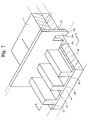
- a plurality of comb teeth 12b are formed at equal intervals and in the same direction in blade 12 that is penetrated into paste film 11.
- This blade 12 is made from metal, ceramic, or plastic and so forth that does not react with the paste and is not dissolved in the paste, and from the viewpoints of dimensional accuracy and durability in particular, ceramic or an alloy containing Fe, Ni, and Co is preferable.
- Each comb tooth 12b is formed so that the gap between them corresponds to the cross-sectional shape of ribs 13 formed by blade 12.
- the shape of the gaps of comb teeth 12b is not only the case of forming a rectangular shape as shown in FIG. 5, but rather the shape of the gaps of comb teeth 12b may form a trapezoidal shape or inverted trapezoidal shape according to the application of the FPD ultimately produced. If the shape of the gaps of comb teeth 12b is made to be trapezoidal, ribs 13 can be formed that are suited for applications having wide openings, while if the shape of the gaps of comb teeth 12b is made to be inverted trapezoidal, ribs 13 can be formed in which the apices of the ribs have a wide area and are flat.
- the formation of ribs 13 by blade 12 composed in this manner is carried out by penetrating comb teeth 12b of blade 12 into paste film 11, and either moving blade 12 in a fixed direction as indicated with the solid line arrows of FIG. 2 while fixing substrate 10 in the state in which edge 12a is contacted with the surface of substrate 10, or moving substrate 10 in a fixed direction as indicated with the broken line arrows of FIG. 2 while fixing blade 12, to plasticly deform paste film 11.
- the locations corresponding to comb teeth 12b of plate 12 of the paste coated onto the surface of substrate 10 are those locations that move to or are scratched off by the gaps of comb teeth 12b, and only the paste located in the gaps of comb teeth 12b remains on substrate 10 to form ribs 13 on the surface of substrate 10.
- the depth of the grooves of the comb teeth is greater than the thickness of paste film 11
- paste that is scratched off when blade 12 or glass substrate 10 is moved enters the grooves, allowing the formation of ribs 13 having a height equal to or greater than the thickness of paste film 11.
- the paste film in which the low boiling point solvent has been volatilized has a viscosity of 50-1,000 Pa ⁇ s at a shear rate of 20/second, and that paste film 11 is plasticly deformed by penetrating comb teeth 12b of blade 12 and moving in a fixed direction relative to paste film 11, the paste is deformed to ribs of a desired shape, the ribs 13 are held in the shape following deformation without returning to its original shape even after the above external force is removed, and ribs 13 of a desired shape corresponding to the shape of the gaps of comb teeth 12 are formed on the surface of substrate 10.
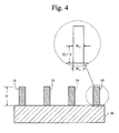
- ceramic ribs 14 result as shown in FIG. 4 that do not lose their shape.
- one or more high boiling point solvents, and one or more low boiling point solvents for which the boiling differs from that of the high boiling point solvent by 30°C or more are contained in the paste, and since only one or more low boiling point solvents are volatilized prior to formation of ribs 13, in comparison with the case of containing only one kind of solvent, there is no occurrence of uneven volatilization of solvents in paste film 11, the shape of ribs 13 formed by plasticly deforming the paste film 11 by blade 12 is favorably maintained, and ceramic ribs 14 having a uniform shape are obtained over the entire glass substrate 10.
- These ceramic ribs can then be used to produce an FPD such as a PDP or PALC not shown.
- paste film 11 may also be plasticly deformed by penetrating comb teeth 12b of blade 12 into paste film 11 formed on the surface of substrate 10 and moving blade 12 or substrate 10 in a fixed direction in the state in which edge 12a of blade 12 is lifted from the surface of substrate 10 at a prescribed height.
- undercoating layer 22 and ribs 23 on this undercoating layer can be formed on the surface of substrate 10.
- paste up to a prescribed height from the surface of substrate 10 remains on the surface of the substrate and undercoating layer 22 is formed by the movement of blade 12 of substrate 10, and the locations corresponding to comb teeth 12b of blade 12 in the paste above this undercoating layer 22 either move to or are scratched off by the gaps of comb teeth 12b, and only the paste located in the gaps of comb teeth 12b remains on undercoating layer 22, while ribs 23 are formed on undercoating layer 22.
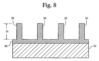
- dielectric layer 24 is formed on substrate 10, and ceramic ribs 25 are formed on this dielectric layer 24.
- 80 wt% of PbO-SiO 2 -B 2 O 3 -based glass powder having an average particle diameter of 1 ⁇ m, and 20 wt% of aluminum powder having an average particle diameter of 0.5 ⁇ m as a ceramic filler were mixed well.
- This mixed powder, ethyl cellulose as a resin, ⁇ -turpentineol as the high boiling point solvent and 1-ethyoxy-2-propanol as the low boiling point solvent were weighed out to a weight ratio of 80/1/14/7.
- This weighed mixed powder, the resin and the high boiling point solvent were first blended and kneaded well to obtain a mixture.
- the weighed low boiling point solvent, 1-ethoxy-2-propanol was then added to this mixture and kneaded to obtain a paste.
- a blade 12 formed from stainless steel having a thickness of 0.1 mm was prepared in which the pitch P of comb teeth 12b was 360 ⁇ m, the gap w of comb teeth 12b was 180 ⁇ m, and the depth h was 300 ⁇ m (FIGS. 5 and 6). Comb teeth 12b of this blade 12 were then penetrated into the paste film from which the low boiling point solvent had been vaporized, and blade 12 was moved in a fixed direction as indicated with the solid line arrow of FIG. 2 in the state in which edge 12a was in contact with glass substrate 10 to plasticly deform paste film 11 and form ribs 13 on the surface of substrate 10.
- ribs 13 were dried for 20 minutes in air at 150°C to eliminate the high boiling point solvent, and then baked for 10 minutes in air at 550°C to form ceramic ribs 14.
- Example 1 The same mixed powder as Example 1, ethyl cellulose as the resin, and ⁇ -turpentineol as solvent were kneaded at a ratio of 85/1/14 and mixed well to obtain a paste.
- the paste containing a single solvent in this manner was then coated at a thickness of 150 ⁇ m by screen printing onto the same glass substrate as Example 1 to form paste film 11.
- ceramic ribs 14 were obtained using the same procedure as Example 1.
- Example 2 The same mixed powder as Example 1, ethyl cellulose as the resin, ⁇ -turpentineol as the high boiling point solvent and 1-ethoxy-2-propanol as the low boiling point solvent were blended at a weight ratio of 80/1/14/7 and kneaded well to obtain a paste. Ceramic ribs were obtained using the same procedure as Example 1 with the exception of obtaining the paste by simultaneously kneading the high boiling point solvent and the low boiling point solvent in this manner.
- Example 1 The paste of Example 1 was coated at a thickness of 150 ⁇ m onto the same glass substrate 10 as Example 1 using a table coater to form paste film 11, and comb teeth 12b of blade 12 were penetrated into the paste film without vaporizing the low boiling point solvent of 1-ethoxy-2-propanol to form ribs 13 on the surface of substrate 10 by moving blade 12 in a fixed direction. Subsequently, these ribs 13 were dried and baked under the same conditions as Example 1 to obtain ceramic ribs.
- the height H and width were measured for 100 randomly selected ceramic ribs 14 obtained in Example 1 and Comparative Examples 1 through 3. As shown in FIG. 4, the width of the ceramic ribs was measured by measuring rib width Wc at height (1/2) H when the height of the ceramic ribs is taken to be H.
- the H dispersion and the Wc dispersion of the ceramic ribs of Example 1 can be seen to be significantly smaller than that of Comparative Examples 1 through 3.
- the reason for the small dispersion in the ceramic ribs of Example 1 is due to the ribs being formed after volatilizing the low boiling point solvent, thereby making the viscosity of the paste comparatively high and reducing sagging of the ribs.
- the reason for the large dispersion in the ceramic ribs of Comparative Example 1 is due to only a single solvent having a comparatively high boiling point being contained in the paste, thereby making the viscosity of the paste comparatively high such that when that paste is coated onto the substrate and spread to a uniform thickness, unevenness occurs in its thickness.
- the reason for the large dispersion in the ceramic ribs of Comparative Example 2 is due to the low boiling point solvent having conformed around the powder in the glass powder or glass-ceramic mixed powder together with the high boiling point solvent since the high boiling point solvent and the low boiling point solvent were mixed simultaneously, thereby causing unevenness to occur in volatilization of the low boiling point solvent when substrate 10 on which paste film 11 was formed was allowed to stand for 1 hour at room temperature, and the resulting unevenness in viscosity of the paste film throughout the substrate causing sagging of the formed ribs to occur non-uniformly.
- the reason for the ceramic ribs in Comparative Example 3 being unable to be measured is that, since the low boiling point solvent was not vaporized, the viscosity of the paste was extremely low, thereby preventing the formation of ribs.
- 80 wt% of PbO-SiO 2 -B 2 O 3 -based glass powder having an average particle diameter of 1 ⁇ m, and 20 wt% of aluminum powder having an average particle diameter of 0.5 ⁇ m as a ceramic filler were prepared and mixed well.
- This mixed powder, ethyl cellulose as the resin, diethylene glycol dibutyl ether as the ether high boiling point solvent and nonane as the hydrocarbon low boiling point solvent were weighed out to a weight ratio of 80/1/14/7.
- This weighed mixed powder, the resin and the high boiling point solvent were first blended and kneaded well to obtain a mixture.
- the weighed low boiling point solvent, nonane was then added to this mixture and kneaded to obtain a paste.
- a paste was obtained in which ethylcyclohexane was added as the low boiling point solvent using the same procedure as Example 2 with the exception of using hydrocarbon solvent, ethylcyclohexane, as the low boiling point solvent.
- a paste was obtained in which xylene was added as the low boiling point solvent using the same procedure as Example 2 with the exception of using the hydrocarbon solvent, xylene, as the low boiling point solvent.
- a paste was obtained in which dibutyl ether was added as the low boiling point solvent using the same procedure as Example 2 with the exception of using the ether solvent, dibutyl ether, as the low boiling point solvent.
- a paste was obtained in which diethylene glycol dimethyl ether was added as the low boiling point solvent using the same procedure as Example 2 with the exception of using the ether solvent, diethylene glycol dimethyl ether, as the low boiling point solvent.
- a paste was obtained in which anisole was added as the low boiling point solvent using the same procedure as Example 2 with the exception of using the ether solvent, anisole, as the low boiling point solvent.
- a paste was obtained in which diethyl carbonate was added as the low boiling point solvent using the same procedure as Example 2 with the exception of using the ester solvent, diethyl carbonate, as the low boiling point solvent.
- a paste was obtained in which isopentyl acetate was added as the low boiling point solvent using the same procedure as Example 2 with the exception of using the ester solvent, isopentyl acetate, as the low boiling point solvent.
- a paste was obtained in which 1-butanol was added as low boiling point solvent using the same procedure as Example 2 with the exception of using the alcohol-based solvent, 1-butanol, as the low boiling point solvent.
- This paste was designated as Comparative Example 4.
- a paste was obtained in which 4-methyl-2-pentanol was added as the low boiling point solvent using the same procedure as Example 2 with the exception of using the alcohol solvent, 4-methyl-2-pentanol, as the low boiling point solvent.
- a paste was obtained in which 1-ethoxy-2-propanol was added as the low boiling point solvent using the same procedure as Example 2 with the exception of using the alcohol-ether solvent, 1-ethoxy-2-propanol, as the low boiling point solvent.
- Example 2 through 9 and Comparative Examples 4 through 6 were divided into two portions, and one of the divided portions of each paste was immediately coated at a thickness of 150 ⁇ m by screen printing onto the same glass substrate as Example 1 to form paste film 11. Subsequently, ceramic ribs 14 were obtained using the same blade 12 as Example 1 according to the same procedure as Example 1.
- each paste was respectively placed in separate sealed containers and stored for 120 hours in an atmosphere at 30°C. After 120 hours elapsed, each of the paste portions were removed from their sealed containers and coated at a thickness of 150 ⁇ m by screen printing onto the same glass substrate as Example 1 to form paste film 11. Subsequently, ceramic ribs 14 were obtained using the same blade 12 as Example 1 according to the same procedure as Example 1.
Landscapes
- Chemical & Material Sciences (AREA)
- Life Sciences & Earth Sciences (AREA)
- Geochemistry & Mineralogy (AREA)
- Engineering & Computer Science (AREA)
- Chemical Kinetics & Catalysis (AREA)
- General Chemical & Material Sciences (AREA)
- Materials Engineering (AREA)
- Organic Chemistry (AREA)
- Environmental Sciences (AREA)
- Glass Compositions (AREA)
- Gas-Filled Discharge Tubes (AREA)
- Paints Or Removers (AREA)
- Liquid Crystal (AREA)
- Surface Treatment Of Glass (AREA)
Applications Claiming Priority (4)
| Application Number | Priority Date | Filing Date | Title |
|---|---|---|---|
| JP2001001180 | 2001-01-09 | ||
| JP2001001180 | 2001-01-09 | ||
| JP2001280202 | 2001-09-14 | ||
| JP2001280202A JP2002274884A (ja) | 2001-01-09 | 2001-09-14 | セラミックリブを形成するためのペースト及びその製造方法並びにそれを用いたリブ状物の形成方法 |
Publications (1)
| Publication Number | Publication Date |
|---|---|
| EP1221431A1 true EP1221431A1 (fr) | 2002-07-10 |
Family
ID=26607387
Family Applications (1)
| Application Number | Title | Priority Date | Filing Date |
|---|---|---|---|
| EP02000163A Withdrawn EP1221431A1 (fr) | 2001-01-09 | 2002-01-08 | Pâte pour la formation de nervures céramiques, méthode de production et méthode de formation de nervures utilisant cette pâte |
Country Status (5)
| Country | Link |
|---|---|
| US (1) | US20020155937A1 (fr) |
| EP (1) | EP1221431A1 (fr) |
| JP (1) | JP2002274884A (fr) |
| KR (2) | KR100510432B1 (fr) |
| TW (1) | TWI306176B (fr) |
Cited By (1)
| Publication number | Priority date | Publication date | Assignee | Title |
|---|---|---|---|---|
| EP1628320A1 (fr) * | 2004-07-22 | 2006-02-22 | LG Electronics Inc. | Composition pour la formation d'une structure à nervures barriere, pour fabrication des écrans à plasma |
Families Citing this family (6)
| Publication number | Priority date | Publication date | Assignee | Title |
|---|---|---|---|---|
| KR100388698B1 (ko) * | 1998-01-30 | 2003-06-25 | 미쓰비시 마테리알 가부시키가이샤 | 세라믹 캐필러리 리브 형성 방법, 그에 사용되는 세라믹 페이스트 및 그 형성 장치 |
| TW200536799A (en) | 2004-03-23 | 2005-11-16 | Nippon Electric Glass Co | Material for forming barrier rib in a plasma display panel |
| TWI262782B (en) * | 2005-06-07 | 2006-10-01 | Nat Applied Res Lab Nat Ce | Method for exercise tolerance measurement |
| US20130056537A1 (en) * | 2011-09-06 | 2013-03-07 | E. I. Du Pont De Nemours And Company | Barrier layer dielectric for rfid circuits |
| KR102074233B1 (ko) * | 2018-12-14 | 2020-02-06 | (주) 동화미생물연구소 | 가축 사체 분해용 조성물 및 이를 포함하는 미생물 제제 |
| CN116314369B (zh) * | 2023-02-14 | 2024-06-18 | 英利能源发展(保定)有限公司 | 一种用于改善N型TOPCon晶硅电池背面印刷效果的银浆及其制备方法 |
Citations (8)
| Publication number | Priority date | Publication date | Assignee | Title |
|---|---|---|---|---|
| US5240884A (en) * | 1991-09-05 | 1993-08-31 | Johnson Matthey, Inc. | Silver-glass die attach paste |
| EP0722179A2 (fr) * | 1994-12-05 | 1996-07-17 | E.I. Du Pont De Nemours And Company | Composition d'isolante, bande non ouvrée et méthode de formation des barrières entretoises pour afficheur à plasma |
| US5801108A (en) * | 1996-09-11 | 1998-09-01 | Motorola Inc. | Low temperature cofireable dielectric paste |
| US5840107A (en) * | 1998-03-25 | 1998-11-24 | Motorola, Inc. | Binder solution for a sealing composition and method of use |
| JPH1184638A (ja) * | 1997-09-11 | 1999-03-26 | Toray Ind Inc | 感光性ガラスペーストおよびプラズマディスプレイの製造方法 |
| JPH11283497A (ja) * | 1998-01-30 | 1999-10-15 | Mitsubishi Materials Corp | セラミックキャピラリリブの形成方法及びこれに用いるペースト並びにブレード |
| JP2000185937A (ja) * | 1998-12-21 | 2000-07-04 | Mitsubishi Materials Corp | セラミックキャピラリリブ形成用ペースト |
| WO2000073227A1 (fr) * | 1999-06-01 | 2000-12-07 | Alliedsignal Inc. | Excipients et pates utilises pour la serigraphie de fritte de verre par combustion a basse temperature |
Family Cites Families (2)
| Publication number | Priority date | Publication date | Assignee | Title |
|---|---|---|---|---|
| US4550982A (en) * | 1981-11-09 | 1985-11-05 | Nippon Electric Co., Ltd. | All-solid-state display including an organic electrochromic layer with ion donor/acceptor |
| DE4315191A1 (de) * | 1993-05-07 | 1994-12-08 | Teroson Gmbh | Plastisolzusammensetzung |
-
2001
- 2001-09-14 JP JP2001280202A patent/JP2002274884A/ja not_active Withdrawn
-
2002
- 2002-01-03 KR KR10-2002-0000223A patent/KR100510432B1/ko not_active Expired - Fee Related
- 2002-01-04 US US10/035,224 patent/US20020155937A1/en not_active Abandoned
- 2002-01-08 EP EP02000163A patent/EP1221431A1/fr not_active Withdrawn
- 2002-01-09 TW TW091100204A patent/TWI306176B/zh active
-
2005
- 2005-04-13 KR KR1020050030612A patent/KR20050042284A/ko not_active Ceased
Patent Citations (8)
| Publication number | Priority date | Publication date | Assignee | Title |
|---|---|---|---|---|
| US5240884A (en) * | 1991-09-05 | 1993-08-31 | Johnson Matthey, Inc. | Silver-glass die attach paste |
| EP0722179A2 (fr) * | 1994-12-05 | 1996-07-17 | E.I. Du Pont De Nemours And Company | Composition d'isolante, bande non ouvrée et méthode de formation des barrières entretoises pour afficheur à plasma |
| US5801108A (en) * | 1996-09-11 | 1998-09-01 | Motorola Inc. | Low temperature cofireable dielectric paste |
| JPH1184638A (ja) * | 1997-09-11 | 1999-03-26 | Toray Ind Inc | 感光性ガラスペーストおよびプラズマディスプレイの製造方法 |
| JPH11283497A (ja) * | 1998-01-30 | 1999-10-15 | Mitsubishi Materials Corp | セラミックキャピラリリブの形成方法及びこれに用いるペースト並びにブレード |
| US5840107A (en) * | 1998-03-25 | 1998-11-24 | Motorola, Inc. | Binder solution for a sealing composition and method of use |
| JP2000185937A (ja) * | 1998-12-21 | 2000-07-04 | Mitsubishi Materials Corp | セラミックキャピラリリブ形成用ペースト |
| WO2000073227A1 (fr) * | 1999-06-01 | 2000-12-07 | Alliedsignal Inc. | Excipients et pates utilises pour la serigraphie de fritte de verre par combustion a basse temperature |
Non-Patent Citations (3)
| Title |
|---|
| PATENT ABSTRACTS OF JAPAN vol. 1999, no. 08 30 June 1999 (1999-06-30) * |
| PATENT ABSTRACTS OF JAPAN vol. 2000, no. 01 31 January 2000 (2000-01-31) * |
| PATENT ABSTRACTS OF JAPAN vol. 2000, no. 10 17 November 2000 (2000-11-17) * |
Cited By (2)
| Publication number | Priority date | Publication date | Assignee | Title |
|---|---|---|---|---|
| EP1628320A1 (fr) * | 2004-07-22 | 2006-02-22 | LG Electronics Inc. | Composition pour la formation d'une structure à nervures barriere, pour fabrication des écrans à plasma |
| US7442738B2 (en) | 2004-07-22 | 2008-10-28 | Lg Electronics Inc. | Barrier rib formation composition for manufacturing plasma display panel |
Also Published As
| Publication number | Publication date |
|---|---|
| TWI306176B (en) | 2009-02-11 |
| KR20020060079A (ko) | 2002-07-16 |
| US20020155937A1 (en) | 2002-10-24 |
| KR20050042284A (ko) | 2005-05-06 |
| JP2002274884A (ja) | 2002-09-25 |
| KR100510432B1 (ko) | 2005-08-26 |
Similar Documents
| Publication | Publication Date | Title |
|---|---|---|
| US20020155937A1 (en) | Paste for forming ceramic ribs, production method for the same and forming method of ribs used the same | |
| JP4692918B2 (ja) | 封着材料 | |
| US20090021686A1 (en) | Method for gravure printing transparent electrodes, an dink composition therefor | |
| KR20110013279A (ko) | 적층 세라믹 부품 제조용 용제 조성물 | |
| JP2000129161A (ja) | Fpd保護膜用コーティング液及びその調製方法 | |
| JP3387833B2 (ja) | セラミックキャピラリリブの形成方法及びこれを用いたセラミックリブの形成方法 | |
| JP2010161063A (ja) | 導電性ペースト組成物及び該組成物を用いた電極の製造方法 | |
| JPS6159351B2 (fr) | ||
| JPH11172169A (ja) | パターン形成用ペースト及びパターン形成方法 | |
| JPS6230225A (ja) | 透明絶縁被膜形成用ペ−スト | |
| JP2003020253A (ja) | ペーストの製造方法及びそれを用いたリブ状物の形成方法 | |
| JP3427884B2 (ja) | セラミックリブを形成するためのペースト | |
| JPS5927963A (ja) | 透明被膜形成用ペ−ストおよび透明被膜 | |
| JPS5933702A (ja) | 透明導電性被膜形成用ペ−スト | |
| JP2000185937A (ja) | セラミックキャピラリリブ形成用ペースト | |
| DE602005004708T2 (de) | Verfahren zur Herstellung von Plasma Anzeigetafeln | |
| KR20030061354A (ko) | 전극 피복용 유리 조성물 및 전극 피복용 유리 형성용도료, 및 그것을 이용한 플라즈마 디스플레이 패널과 그제조 방법 | |
| JPH09286955A (ja) | パターン形成用ペーストおよびパターン形成方法 | |
| JP3528967B2 (ja) | セラミックキャピラリリブの形成方法 | |
| JPS6048742B2 (ja) | 液晶セル基板とその製造方法 | |
| JPS6159352B2 (fr) | ||
| JPS6310844B2 (fr) | ||
| KR100717546B1 (ko) | 플라즈마 디스플레이 패널의 투명유전체 형성용 페이스트조성물 | |
| JPS6148587B2 (fr) | ||
| JPH05105476A (ja) | 透明導電膜とその形成方法 |
Legal Events
| Date | Code | Title | Description |
|---|---|---|---|
| PUAI | Public reference made under article 153(3) epc to a published international application that has entered the european phase |
Free format text: ORIGINAL CODE: 0009012 |
|
| AK | Designated contracting states |
Kind code of ref document: A1 Designated state(s): AT BE CH CY DE DK ES FI FR GB GR IE IT LI LU MC NL PT SE TR |
|
| AX | Request for extension of the european patent |
Free format text: AL;LT;LV;MK;RO;SI |
|
| 17P | Request for examination filed |
Effective date: 20030103 |
|
| RIN1 | Information on inventor provided before grant (corrected) |
Inventor name: HASHIMOTO, IKIKO,MITSUBISHI MATERIALS CORPORATION Inventor name: KANDA, YOSHIO,MITSUBISHI MATERIALS CORPORATION Inventor name: KUROMITSU, YOSHIROU,MITSUBISHI MATERIALS CORP. Inventor name: UESUGI, RYUJI,MITSUBISHI MATERIALS CORPORATION Inventor name: CHUNG, SEUNG JAE Inventor name: YOSHIKAWA, KANZO Inventor name: KANG, YOUNG CHEUL Inventor name: KIM, JOON MIM |
|
| AKX | Designation fees paid |
Designated state(s): DE FR GB NL |
|
| 17Q | First examination report despatched |
Effective date: 20040712 |
|
| STAA | Information on the status of an ep patent application or granted ep patent |
Free format text: STATUS: THE APPLICATION IS DEEMED TO BE WITHDRAWN |
|
| 18D | Application deemed to be withdrawn |
Effective date: 20101002 |