EP1221508A2 - Amortisseur d'impact pour véhicule - Google Patents
Amortisseur d'impact pour véhicule Download PDFInfo
- Publication number
- EP1221508A2 EP1221508A2 EP01309844A EP01309844A EP1221508A2 EP 1221508 A2 EP1221508 A2 EP 1221508A2 EP 01309844 A EP01309844 A EP 01309844A EP 01309844 A EP01309844 A EP 01309844A EP 1221508 A2 EP1221508 A2 EP 1221508A2
- Authority
- EP
- European Patent Office
- Prior art keywords
- tubes
- compression
- rail
- array
- transverse
- Prior art date
- Legal status (The legal status is an assumption and is not a legal conclusion. Google has not performed a legal analysis and makes no representation as to the accuracy of the status listed.)
- Withdrawn
Links
- 230000006835 compression Effects 0.000 claims abstract description 69
- 238000007906 compression Methods 0.000 claims abstract description 69
- 230000001154 acute effect Effects 0.000 claims abstract 3
- 230000003116 impacting effect Effects 0.000 abstract description 11
- 239000000463 material Substances 0.000 description 3
- 239000004705 High-molecular-weight polyethylene Substances 0.000 description 2
- 229920001903 high density polyethylene Polymers 0.000 description 2
- 239000004700 high-density polyethylene Substances 0.000 description 2
- 229910052751 metal Inorganic materials 0.000 description 2
- 239000004698 Polyethylene Substances 0.000 description 1
- 230000002411 adverse Effects 0.000 description 1
- 230000004888 barrier function Effects 0.000 description 1
- 239000002131 composite material Substances 0.000 description 1
- 238000010276 construction Methods 0.000 description 1
- 229920001971 elastomer Polymers 0.000 description 1
- 239000000806 elastomer Substances 0.000 description 1
- 239000006260 foam Substances 0.000 description 1
- 239000002184 metal Substances 0.000 description 1
- 238000012986 modification Methods 0.000 description 1
- 230000004048 modification Effects 0.000 description 1
- 229920013716 polyethylene resin Polymers 0.000 description 1
- 238000009419 refurbishment Methods 0.000 description 1
Images





Classifications
-
- E—FIXED CONSTRUCTIONS
- E01—CONSTRUCTION OF ROADS, RAILWAYS, OR BRIDGES
- E01F—ADDITIONAL WORK, SUCH AS EQUIPPING ROADS OR THE CONSTRUCTION OF PLATFORMS, HELICOPTER LANDING STAGES, SIGNS, SNOW FENCES, OR THE LIKE
- E01F15/00—Safety arrangements for slowing, redirecting or stopping errant vehicles, e.g. guard posts or bollards; Arrangements for reducing damage to roadside structures due to vehicular impact
- E01F15/14—Safety arrangements for slowing, redirecting or stopping errant vehicles, e.g. guard posts or bollards; Arrangements for reducing damage to roadside structures due to vehicular impact specially adapted for local protection, e.g. for bridge piers, for traffic islands
- E01F15/145—Means for vehicle stopping using impact energy absorbers
- E01F15/146—Means for vehicle stopping using impact energy absorbers fixed arrangements
Definitions
- the present invention relates to impact attenuators for vehicles that have left the roadway, and in particular to such attenuators that are well adapted to bring an axially impacting vehicle to a safe stop and to redirect a laterally impacting vehicle that strikes the side of the attenuator.
- Carney U.S. Patents 4,645,375 and 5,011,326 disclose two stationary impact attenuation systems. Both rely on an array of vertically oriented metal cylinders.
- compression elements 54 are arranged in selected cylinders transverse to the longitudinal axis of the array.
- the cylinders are guided in longitudinal movement by cables extending alongside the cylinders on both outer faces of the array. The individual cylinders are guided along the cables by eye-bolts or U-bolts.
- the impact attenuators described below include a central, elongated structure that is designed to resist lateral deflection.
- Tubes are mounted on either side of this elongated structure to slide along the structure in an axial impact and to react against the structure and redirect the vehicle in a lateral impact.
- the tubes are formed of a resilient, self-restoring material such as an elastomer or a high-density, high-molecular-weight polyethylene.
- Compression elements are mounted in the cylinders, and these compression elements are oriented at an angle of about 60° to the longitudinal axis of the array to improve the redirection capabilities of the system.
- Figure 1 shows an overall view of a vehicle impact attenuator 10 in an initial condition, prior to impact.
- the attenuator 10 is shown positioned forwardly of a backup 12, which can be any hazard alongside a roadway from which vehicles are to be protected.
- the backup 12 can be a bridge pier, a wall, or other obstruction positioned alongside the roadway.
- the attenuator 10 includes an array 14 of tubes 16.
- all of the tubes 16 are cylindrical in shape, and they are oriented with their cylinder axes positioned vertically.
- the tubes 16 are preferably formed of a resilient, polymeric material, such as high density polyethylene (HDPE), such that the tubes 16 are self-restoring after an impact.
- HDPE high density polyethylene
- self-restoring signifies that the tubes return substantially (though not in all cases completely) to their original condition after at least some impacts. Thus, the tube does not have to return to exactly its original condition to be considered self-restoring.
- the array 14 defines a longitudinal axis 18 extending forwardly from the backup 12, and the array 14 includes a front end 20 positioned farther from the backup than the back end 22.
- each of the rows includes two adjacent tubes, each disposed on a respective side of the longitudinal axis 18.
- Each of these tubes includes a compression element 24 that is designed to resist compression of the respective tube 16 along a respective compression axis 26, while allowing elongation of the tube 16 along the same axis 26 and collapse of the tube along the longitudinal axis of the array.
- an elongated structure 28 takes the form of a rail 30 that is secured in place in alignment with the longitudinal axis 18, for example, by bolting the rail 30 to the support surface.
- This rail may take the form of the rail described in U.S. Patent 5,733,062, assigned to the assignee of the present invention and hereby incorporated by reference.
- the attenuator 10 also includes a plurality of guides 32.
- each of the guides 32 includes a transverse element 34 that is secured to adjacent ones of the tubes 16 and is configured to slide along the length of the rail 30, in an axial impact.
- the transverse elements 34 slide along the rail 30, and the tubes 16 are flattened along the longitudinal direction. Deformation of the tubes 16 absorbs kinetic energy and decelerates the impacting vehicle.
- the compression elements 24 transfer compressive loads to the transverse elements 34, which in turn transfer these compressive loads to the rail 30.
- This provides substantial lateral stiffness to the attenuator 10 such that the attenuator 10 redirects an impacting vehicle that strikes the attenuator 10 laterally. Because the guides 32 and the elongated structure 28 are positioned centrally, a vehicle traveling down the side of the attenuator 10 encounters few snagging surfaces that might adversely affect the stability or trajectory of the impacting vehicle.
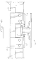
- FIG. 2 provides a more detailed view of selected elements of the attenuator 10.
- the transverse element 34 in this embodiment is shaped as a frame with substantial stiffness, and that it is provided with plates 38 shaped to fit under an uppermost flange of the rail 30 (Figure 1) such that the transverse element 34 is restrained from all translation other than axial sliding movement along the length of the rail 30.
- Each transverse element includes two legs 40 that rest on the support surface on opposite sides of the rail. In the event of a lateral impact, the leg on the side of the rail opposite the impact cooperates with the plates 38 and the rail 30 to resist rotation and lifting of the transverse element 34.
- the plates 38 are shaped to allow twisting of the transverse element 34 about a vertical axis over a desired range (e.g., ⁇ 25°) to reduce binding with the rail 30.
- Figures 3 and 4 show details of construction of the plates 38 and the rail 30. Note that the fit between the plates 38 and the rail 30 is loose, and this fit allows the desired degree of twisting of the transverse element without binding.
- the range of allowed twisting is preferably greater than ⁇ 10°, more preferably greater than ⁇ 20°, and most preferably about ⁇ 25°, all measured with respect to the longitudinal axis of the rail 30.
- the dimensions of Table 1 have been found suitable in one example, in which the plates 38 were shaped as shown in Figure 4a, and the plates 38 extended 7.6 cm along the rail (including the chamfered corners).
- Parameter Dimension (cm) A 0.47 B 1.59 C 1.11
- Figure 5 shows one of the transverse elements 34 twisted by 25° with respect to the rail 30.
- the plates 38 may present a curved bullet nose to the rail.
- each of the compression elements 24 is secured at one end only to the respective tube 16, as for example by suitable fasteners such as bolts.
- Each compression element 24 extends substantially completely across the respective tube 16 in the initial condition (e.g., by more than about 80% of the tube diameter), and it is designed to resist compression while allowing extension of the tube 16 along the compression axis 26.
- one end of each of the compression elements 24 is free of tension-resisting attachment to the respective tube 16.
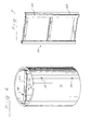
- Figure 6 shows a perspective view of one of the tubes 16 and the associated compression element 24.
- the compression element 24 is shown in greater detail in Figure 7.
- the compression element 24 is shaped as a frame in this embodiment, and the compression element includes openings 25 that receive fasteners (not shown) that secure one end only of each compression element 24 to the respective tube 16.
- FIG. 1 shows only two tubes 16 secured to the transverse element 34, when fully assembled there are a total of four tubes 16 secured to each of the transverse elements 34: two on one side of the rail 30, and two on the other. Thus, each tube 16 is bolted in place between two adjacent transverse elements 34. This arrangement is shown in Figure 1.
- the impacting vehicle In the event of an axial impact, the impacting vehicle first strikes the front end 20. The momentum of the impacting vehicle causes the transverse elements 34 to slide along the rail 30, thereby compressing the tubes 16 such that they become elongated transverse to the longitudinal axis and flattened along the longitudinal axis. In order to prevent any undesired binding, it is preferred that the tubes 16 within any given row be spaced from one another in an initial condition, e.g., by about one-half the diameter of tubes 16. After the impact, the system can be restored to its original configuration by pulling the forward transverse element 34 away from the backup 12. In many cases, nothing more is required by way of refurbishment.
- the impacting vehicle will strike the side of the array 14.
- the compression elements 24 transfer compressive loading to the transverse elements 34, which transfer this compressive loading to the rail 30. In this way, the attenuator 10 provides substantial lateral stiffness and effective redirection of an impacting vehicle.
- each compression element is positioned forwardly of the inboard end of each compression element, at the illustrated angle with the longitudinal axis.
- other angles can be used.
- the array 10 may have a length of 9.1 meters, and each of the tubes may have a height of 102 cm and a diameter of 61 cm.
- the tubes 16 may be formed of Extra High Molecular Weight Polyethylene resin (e.g., EHMW PE 408 ASTM F714) with a wall thickness of 1.875 (for tubes 16 at the front of the array) and 2.903 cm (for tubes 16 at the rear of the array), all as specified by ASTM F714. All of these dimensions may be varied to suit the particular application.
- Figure 8 shows an alternative form of the transverse element 34.
- the transverse element 34 is provided with slots positioned to receive the fasteners that secure the tubes to the transverse element.
- the slots allow the tubes to move laterally outwardly as necessary during an axial impact to prevent any undesired binding between the tubes within a row at the centerline.
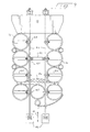
- Figure 9 relates to another alternative embodiment in which the elongated structure that provides lateral rigidity is implemented as a set of cables 44.
- These cables 44 are positioned to support a central portion of the tubes 16, and the tubes 16 are secured to the cables 44 by means of guides 45 that may take the form of eye-bolts or U-bolts.
- the compression elements 24 are positioned transversely to the longitudinal axis 18 and are secured to the guides 45.
- Load-sharing diaphragms 46 are provided to transfer lateral loads from one of the cables to the other.
- the cables are anchored rearwardly to the backup 12 and forwardly to ground anchors 46. If desired, extra redirecting cylinders 48 may be positioned between the tubes 16.
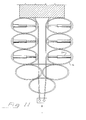
- Figures 10 and 11 relate to a third embodiment that is similar to the embodiment of Figure 9 in many ways.
- Figure 10 shows the system prior to impact with a vehicle
- Figure 11 shows the system following an axial impact.
- the compression elements 24 are designed to resist collapse of the tubes 16 in the lateral direction, while allowing expansion of the tubes 16 in the lateral direction.
- Figures 10 and 11 uses a modified compression element 24 that is telescoping and is secured at both ends to the tube 16.
- Figure 12 shows the telescoping compression element in its initial condition
- Figure 13 shows the telescoping compression element during an axial impact when the tube 16 is elongated.
- a tension spring 50 can be provided to restore the distorted tube 16 to the initial condition of Figure 12 after an impact.
- the telescoping compression element of these figures can be used in any of the embodiments described above.
- the tubes 16 can be formed of a wide variety of materials, and may be non-circular in cross section (e.g. rectangular, oval, or triangular).
- the compression elements can be shaped either as frames or struts, as described above, or alternately as panels or other shapes designed to resist compression effectively. In some cases, a single compression element can be placed within each tube. In other cases, multiple compression elements may be placed within each tube, for example at varying heights.
- the guides described above can take many forms, including guides adapted to slide along a cable as well as guides adapted to slide along one or more rails.
- the guides may or may not include transverse elements, and if so the transverse elements may be shaped differently than those described above.
- rigid panels may be substituted for the disclosed frames.
- a separate guide may be provided for each tube rather than having a single transverse element to which multiple tubes are mounted.
- two or more tubes that are spaced along the longitudinal axis of the array may have no guide therebetween.
- the angle of the compression axes, the number of transverse elements 34 per system, the number of tubes per system, the location of the compression elements within the tubes, and the number of compression elements per tube may all be varied as appropriate for the particular application. Also, it is not essential that every tube include a compression element or that every tube be directly connected to a guide, and selective use of compression elements and/or guides with only some of the tubes is contemplated.
- tube is intended broadly to encompass tubes of any desired cross-section. Thus, a tube does not have to be circular in cross-section as in the illustrated embodiment.
- compression element is intended to encompass a wide variety of structures that effectively resist compressive loads along a compression axis while allowing substantial compression transverse to the compression axis.
Landscapes
- Engineering & Computer Science (AREA)
- Architecture (AREA)
- Civil Engineering (AREA)
- Structural Engineering (AREA)
- Vibration Dampers (AREA)
- Refuge Islands, Traffic Blockers, Or Guard Fence (AREA)
Applications Claiming Priority (2)
| Application Number | Priority Date | Filing Date | Title |
|---|---|---|---|
| US09/753,476 US6461076B1 (en) | 2001-01-03 | 2001-01-03 | Vehicle impact attenuator |
| US753476 | 2001-01-03 |
Publications (2)
| Publication Number | Publication Date |
|---|---|
| EP1221508A2 true EP1221508A2 (fr) | 2002-07-10 |
| EP1221508A3 EP1221508A3 (fr) | 2005-04-27 |
Family
ID=25030790
Family Applications (1)
| Application Number | Title | Priority Date | Filing Date |
|---|---|---|---|
| EP01309844A Withdrawn EP1221508A3 (fr) | 2001-01-03 | 2001-11-22 | Amortisseur d'impact pour véhicule |
Country Status (6)
| Country | Link |
|---|---|
| US (3) | US6461076B1 (fr) |
| EP (1) | EP1221508A3 (fr) |
| JP (1) | JP2002227151A (fr) |
| AU (2) | AU783161B2 (fr) |
| HK (1) | HK1045546A1 (fr) |
| IL (3) | IL161839A (fr) |
Cited By (5)
| Publication number | Priority date | Publication date | Assignee | Title |
|---|---|---|---|---|
| ITMI20100733A1 (it) * | 2010-04-28 | 2011-10-29 | Autostrade Per L Italia S P A | Dispositivo di sicurezza stradale attenuatore di urti |
| ITUB20155211A1 (it) * | 2015-10-22 | 2017-04-22 | Pasquale Impero | Sistema di guida della deformazione per un dispositivo di sicurezza stradale e gruppo dispositivo di sicurezza stradale |
| EP3222781A1 (fr) * | 2016-03-23 | 2017-09-27 | Sps Schutzplanken Gmbh | Systeme de retenue de vehicule absorbant l'energie |
| DE102004058884B4 (de) | 2004-12-06 | 2018-05-03 | Sps Schutzplanken Gmbh | Anpralldämpfer an Verkehrswegen |
| CN109295896A (zh) * | 2018-11-27 | 2019-02-01 | 成都工业学院 | 岔道口道路防撞装置 |
Families Citing this family (42)
| Publication number | Priority date | Publication date | Assignee | Title |
|---|---|---|---|---|
| US6022003A (en) * | 1994-11-07 | 2000-02-08 | The Board Of Regents Of The University Of Nebraska | Guardrail cutting terminal |
| US8517349B1 (en) | 2000-10-05 | 2013-08-27 | The Texas A&M University System | Guardrail terminals |
| US6461076B1 (en) | 2001-01-03 | 2002-10-08 | Energy Absorption Systems, Inc. | Vehicle impact attenuator |
| EP1458935B1 (fr) * | 2001-11-30 | 2013-10-16 | The Texas A & M University System | Poteau de support flexible en acier pour glissiere de securite |
| US6932327B2 (en) | 2002-01-30 | 2005-08-23 | The Texas A&M University System | Cable guardrail release system |
| US6948703B2 (en) | 2002-01-30 | 2005-09-27 | The Texas A&M University System | Locking hook bolt and method for using same |
| US6863467B2 (en) * | 2002-02-27 | 2005-03-08 | Energy Absorption Systems, Inc. | Crash cushion with deflector skin |
| US7246791B2 (en) * | 2002-03-06 | 2007-07-24 | The Texas A&M University System | Hybrid energy absorbing reusable terminal |
| CN100342085C (zh) | 2002-05-13 | 2007-10-10 | 姜胜求 | 具有缓冲销的车辆撞击吸收装置 |
| US6755453B2 (en) * | 2002-08-29 | 2004-06-29 | Veridian Systems Division, Inc. | Deployable rigid system for crash energy management |
| US6851664B2 (en) * | 2003-05-15 | 2005-02-08 | Walbro Engine Management, L.L.C. | Self-relieving choke valve system for a combustion engine carburetor |
| AU2005285021B2 (en) * | 2004-09-15 | 2010-09-16 | Energy Absorption Systems, Inc. | Crash cushion |
| ES2284131T3 (es) * | 2004-10-06 | 2007-11-01 | Tss Technische Sicherheits-Systeme Gmbh | Estructura de transicion. |
| US7775738B2 (en) | 2004-10-22 | 2010-08-17 | Darcy Daniel T | Vehicle barrier system |
| US7168880B2 (en) | 2004-11-17 | 2007-01-30 | Battelle Memorial Institute | Impact attenuator system |
| US7507051B2 (en) * | 2005-12-06 | 2009-03-24 | Mccue Corporation | Adjustable bollard |
| US7507050B2 (en) * | 2005-12-06 | 2009-03-24 | Mccue Corporation | Adjustable bollard |
| US7587790B2 (en) * | 2005-12-06 | 2009-09-15 | Mccue Corporation | Adjustable rigid corner guard |
| JP4791176B2 (ja) * | 2005-12-26 | 2011-10-12 | 株式会社花井製作所 | 追突エネルギー吸収装置 |
| US7794174B2 (en) * | 2007-01-29 | 2010-09-14 | Traffix Devices, Inc. | Crash impact attenuator systems and methods |
| CA2721238C (fr) * | 2008-03-17 | 2015-10-06 | Battelle Memorial Institute | Materiau de controle du rebond |
| US20100003078A1 (en) * | 2008-07-07 | 2010-01-07 | National Taipei University Of Technology | Anti-terror car-attack defending apparatus |
| KR20100132428A (ko) | 2009-06-09 | 2010-12-17 | (주) 임팩트 블랙홀 | 압연관 표면 드래그(drag)에 의한 운동 마찰력과 압연력을 이용한 차량충격을 흡수하는 방법 및 이를 이용한 차량충격흡수장치 |
| DE102010003497B4 (de) * | 2010-03-31 | 2018-04-05 | Benteler Sgl Gmbh & Co. Kg | Verfahren zur Herstellung eines Aufprallschutzelementes |
| US8469626B2 (en) * | 2010-04-15 | 2013-06-25 | Energy Absorption Systems, Inc. | Energy absorbing vehicle barrier |
| KR101150938B1 (ko) * | 2010-08-11 | 2012-05-29 | 신도산업 주식회사 | 충격흡수장치 |
| US8974142B2 (en) | 2010-11-15 | 2015-03-10 | Energy Absorption Systems, Inc. | Crash cushion |
| KR101380411B1 (ko) | 2012-03-19 | 2014-04-02 | 주식회사 스마트에어 챔버 | 충격 흡수용 보조 연결부를 구비한 도로변 충격흡수 장치 |
| US20140160263A1 (en) * | 2012-11-30 | 2014-06-12 | Kabushiki Kaisha Topcon | Data visualization method and apparatus utilizing receiver operating characteristic analysis |
| ITBO20130115A1 (it) * | 2013-03-15 | 2014-09-16 | Impero Pasquale | Attenuatore d'urto stradale |
| JP6273032B2 (ja) * | 2013-11-05 | 2018-01-31 | シンソン コントロール カンパニー リミテッドShinsung Control Co., Ltd. | 衝突衝撃吸収装置 |
| US9051698B1 (en) * | 2014-06-19 | 2015-06-09 | Lindsay Transporation Solutions, Inc. | Crash attenuator apparatus |
| US9404231B2 (en) | 2014-08-26 | 2016-08-02 | The Texas A&M University System | Module for use in a crash barrier and crash barrier |
| US11913182B2 (en) * | 2015-12-09 | 2024-02-27 | Ohio University | Guardrail terminal barrier |
| NL2018015B1 (en) * | 2016-12-16 | 2018-06-26 | Laura Metaal Holding B V | Mounting assembly for a traffic barrier and traffic barrier comprising a mounting assembly |
| WO2021076767A1 (fr) * | 2019-10-15 | 2021-04-22 | Traffix Devices, Inc. | Systèmes et procédés d'atténuateur d'impact de collision |
| CA3170950A1 (fr) | 2020-03-09 | 2021-09-16 | Trinity Highway Products Llc | Coussin de securite |
| CN115698432B (zh) | 2020-06-05 | 2025-09-23 | 瓦尔蒂尔有限责任公司 | 碰撞缓冲器 |
| KR102899745B1 (ko) | 2020-06-19 | 2025-12-11 | 트래픽스 디바이시스 인코포레이티드 | 충돌 충격 감쇠기 시스템 및 방법 |
| CN112267399B (zh) * | 2020-10-27 | 2022-09-23 | 安徽华升项目管理有限公司 | 一种路政侧边防护装置 |
| CN114481731A (zh) * | 2022-01-19 | 2022-05-13 | 广西大学 | 一种具有监测功能的避险车道吸能系统 |
| WO2023178340A1 (fr) * | 2022-03-18 | 2023-09-21 | Hill & Smith Inc. | Ensembles atténuateurs de collision pour faire décélérer des véhicules |
Citations (9)
| Publication number | Priority date | Publication date | Assignee | Title |
|---|---|---|---|---|
| US4352484A (en) | 1980-09-05 | 1982-10-05 | Energy Absorption Systems, Inc. | Shear action and compression energy absorber |
| US4452431A (en) | 1982-05-19 | 1984-06-05 | Energy Absorption Systems, Inc. | Restorable fender panel |
| US4635981A (en) | 1984-10-29 | 1987-01-13 | Energy Absorption Systems, Inc. | Impact attenuating body |
| US4645375A (en) | 1985-05-23 | 1987-02-24 | State Of Connecticut | Stationary impact attenuation system |
| US4674911A (en) | 1984-06-13 | 1987-06-23 | Energy Absorption Systems, Inc. | Energy absorbing pneumatic crash cushion |
| US4711481A (en) | 1985-10-25 | 1987-12-08 | Energy Absorption Systems, Inc. | Vehicle impact attenuating device |
| US5011326A (en) | 1990-04-30 | 1991-04-30 | State Of Connecticut | Narrow stationary impact attenuation system |
| US5733062A (en) | 1995-11-13 | 1998-03-31 | Energy Absorption Systems, Inc. | Highway crash cushion and components thereof |
| US5875875A (en) | 1996-11-05 | 1999-03-02 | Knotts; Stephen Eric | Shock isolator and absorber apparatus |
Family Cites Families (69)
| Publication number | Priority date | Publication date | Assignee | Title |
|---|---|---|---|---|
| US2088087A (en) * | 1936-05-01 | 1937-07-27 | American Rolling Mill Co | Crash bumper and the like |
| US3680662A (en) * | 1970-06-22 | 1972-08-01 | Rich Enterprises Inc John | Liquid shock absorbing buffer |
| US3768781A (en) | 1970-09-04 | 1973-10-30 | Dynamics Res Mfg Inc | Shock absorbing structure |
| US3674115A (en) * | 1970-09-23 | 1972-07-04 | Energy Absorption System | Liquid shock absorbing buffer |
| US3643924A (en) | 1970-09-24 | 1972-02-22 | Fibco Inc | Highway safety device |
| US3693940A (en) | 1970-12-08 | 1972-09-26 | Menasco Mfg Co | Energy absorbing barrier post assembly |
| US3919380A (en) | 1971-12-29 | 1975-11-11 | Union Carbide Corp | Process for expanding annealed thermoformable materials |
| US3845936A (en) | 1973-05-25 | 1974-11-05 | Steel Corp | Modular crash cushion |
| US3880404A (en) | 1973-08-29 | 1975-04-29 | Fibco Inc | Energy absorbing impact attenuating highway safety systems |
| US3856268A (en) | 1973-09-17 | 1974-12-24 | Fibco Inc | Highway safety device |
| US3982734A (en) | 1975-06-30 | 1976-09-28 | Dynamics Research And Manufacturing, Inc. | Impact barrier and restraint |
| US4084914A (en) | 1977-01-28 | 1978-04-18 | Humphrey William D | Self-erecting highway guide post |
| US4190275A (en) | 1978-03-16 | 1980-02-26 | Fibco Inc. | Impact attenuator |
| US4200310A (en) | 1978-07-20 | 1980-04-29 | State Of Connecticut | Energy absorbing system |
| LU80813A1 (de) | 1979-01-23 | 1979-06-05 | Arbed | Leiteinrichtung zur sicherheit im strassenverkehr |
| US4321989A (en) * | 1980-01-22 | 1982-03-30 | Meinco Mfg. Co. | Energy absorbing impact barrier |
| NL8003653A (nl) | 1980-06-24 | 1982-01-18 | Nederlanden Staat | Obstakelbeveiliger. |
| DE3106694A1 (de) | 1981-02-23 | 1982-09-09 | Hermann Hans 8750 Aschaffenburg Urlberger | "stossdaempfende vorrichtung und verwendung derselben in einem schutzplankensystem" |
| US4407484A (en) | 1981-11-16 | 1983-10-04 | Meinco Mfg. Co. | Impact energy absorber |
| US4583716A (en) * | 1982-05-19 | 1986-04-22 | Energy Absorption Systems, Inc. | Universal anchor assembly for impact attenuation device |
| US4784515A (en) | 1983-01-11 | 1988-11-15 | Energy Absorption Systems, Inc. | Collapsible highway barrier |
| US4596489A (en) | 1984-09-13 | 1986-06-24 | Datum Plastic Molding, Inc. | Traffic delineator |
| CH663809A5 (de) | 1984-10-09 | 1988-01-15 | Zemaltech Ag | Sicherheitsueberzug fuer leitplanken. |
| US4815565A (en) | 1986-12-15 | 1989-03-28 | Sicking Dean L | Low maintenance crash cushion end treatment |
| US4844213A (en) | 1987-09-29 | 1989-07-04 | Travis William B | Energy absorption system |
| DE3809470A1 (de) | 1988-03-21 | 1989-10-12 | Sps Schutzplanken Gmbh | Stossdaempfende vorrichtung fuer schutzplankeneinrichtungen |
| US5054954A (en) | 1989-03-16 | 1991-10-08 | International Barrier Corporation | Roadway barrier |
| IT1239582B (it) | 1990-02-07 | 1993-11-10 | C.R.A. Centro Ricerche Applicate | Barriera spartitraffico a dissipazione d'urto. |
| US5112028A (en) | 1990-09-04 | 1992-05-12 | Energy Absorption Systems, Inc. | Roadway impact attenuator |
| FR2691124B1 (fr) | 1992-05-12 | 1994-11-18 | Maximilien Annie | Atténuateur de choc d'un véhicule contre un obstacle fixe. |
| US5403113A (en) | 1992-08-12 | 1995-04-04 | Energy Absorption Systems, Inc. | Shear loading energy absorbing device |
| US5248129A (en) | 1992-08-12 | 1993-09-28 | Energy Absorption Systems, Inc. | Energy absorbing roadside crash barrier |
| US5403112A (en) | 1993-09-08 | 1995-04-04 | Vanderbilt University | Crash impact attenuator constructed from high molecular weight/high density polyethylene |
| US5749673A (en) | 1994-02-10 | 1998-05-12 | Traffix Devices | Stackable vertical panel |
| US5429449A (en) | 1994-05-18 | 1995-07-04 | Baatz; Guenter A. | Rubber adaptor for highway guardrail |
| US5483917A (en) | 1994-09-29 | 1996-01-16 | Walker; Dale L. | Light reflecting traffic direction wand |
| US6220575B1 (en) | 1995-01-18 | 2001-04-24 | Trn Business Trust | Anchor assembly for highway guardrail end terminal |
| US5487619A (en) | 1995-01-24 | 1996-01-30 | Winebrenner; Terence M. | Self-righting warning marker |
| AU5342396A (en) | 1995-04-19 | 1996-11-07 | Barry Michael Frank Jarvis | A resilient buffer |
| US5568913A (en) * | 1995-05-16 | 1996-10-29 | Nagler; Yaacov | Impact absorbing device |
| US5607252A (en) | 1995-06-16 | 1997-03-04 | Tischer; Duain E. | Highway collision containment system |
| US5718413A (en) | 1996-08-13 | 1998-02-17 | Nagler; Yaacov | Safety cushion |
| US5823584A (en) | 1996-10-08 | 1998-10-20 | Vanderbilt University | Vehicle mounted crash impact attenuator |
| US5746419A (en) | 1996-10-16 | 1998-05-05 | General Motors Corporation | Energy absorbing device |
| US6126144A (en) | 1997-03-03 | 2000-10-03 | The Texas A&M University System | Barrel crash cushions |
| US5775675A (en) | 1997-04-02 | 1998-07-07 | Safety By Design, Inc. | Sequential kinking guardrail terminal system |
| US5851005A (en) | 1997-04-15 | 1998-12-22 | Muller; Franz M. | Energy absorption apparatus |
| US6116805A (en) | 1997-05-05 | 2000-09-12 | Gertz; David C. | Crash attenuator with a row of compressible hoops |
| US6024341A (en) * | 1997-05-05 | 2000-02-15 | Traffix Devices, Inc. | Crash attenuator of compressible sections |
| US6293727B1 (en) | 1997-06-05 | 2001-09-25 | Exodyne Technologies, Inc. | Energy absorbing system for fixed roadside hazards |
| US5797592A (en) | 1997-06-16 | 1998-08-25 | Energy Absorption Systems, Inc. | Roadside energy absorbing barrier with improved fender panel fastener |
| US5957435A (en) | 1997-07-11 | 1999-09-28 | Trn Business Trust | Energy-absorbing guardrail end terminal and method |
| WO1999002778A2 (fr) | 1997-07-14 | 1999-01-21 | Vision Molded Plastics, Ltd. | Entretoise destine a porter une glissiere de securite sur un poteau |
| US6203079B1 (en) | 1997-11-24 | 2001-03-20 | Automotive Technologies International, Inc. | Damped crash attenuator |
| US6082926A (en) | 1998-07-28 | 2000-07-04 | Texas A&M University System | Energy absorbant module |
| US6179516B1 (en) * | 1998-07-28 | 2001-01-30 | The Texas A&M University System | Pipe rack crash cushion |
| US6375385B1 (en) | 1998-10-15 | 2002-04-23 | Gregory B. Kennedy | Flexible support |
| US6092959A (en) | 1998-11-16 | 2000-07-25 | Energy Absorption Systems, Inc. | Method for decelerating a vehicle, highway crash cushion, and energy absorbing element therefor |
| US6340268B1 (en) | 1999-04-06 | 2002-01-22 | Dean C. Alberson | Impact attenuating barrier wall |
| US6308809B1 (en) | 1999-05-07 | 2001-10-30 | Safety By Design Company | Crash attenuation system |
| US6309140B1 (en) | 1999-09-28 | 2001-10-30 | Svedala Industries, Inc. | Fender system |
| US6533250B2 (en) | 1999-10-15 | 2003-03-18 | W. Eugene Arthur | Energy dissipating system for a concrete roadway barrier |
| US6276667B1 (en) | 1999-10-15 | 2001-08-21 | W. Eugene Arthur | Energy dissipating system for a concrete barrier |
| US6427983B1 (en) | 2000-10-12 | 2002-08-06 | Energy Absorption Systems, Inc. | Self-restoring highway crash attenuator |
| US6461076B1 (en) | 2001-01-03 | 2002-10-08 | Energy Absorption Systems, Inc. | Vehicle impact attenuator |
| US6554529B2 (en) * | 2001-03-05 | 2003-04-29 | Energy Absorption Systems, Inc. | Energy-absorbing assembly for roadside impact attenuator |
| US6637971B1 (en) | 2001-11-01 | 2003-10-28 | Worcester Polytechnic Institute | Reusable high molecular weight/high density polyethylene guardrail |
| US6863467B2 (en) | 2002-02-27 | 2005-03-08 | Energy Absorption Systems, Inc. | Crash cushion with deflector skin |
| US7246791B2 (en) | 2002-03-06 | 2007-07-24 | The Texas A&M University System | Hybrid energy absorbing reusable terminal |
-
2001
- 2001-01-03 US US09/753,476 patent/US6461076B1/en not_active Expired - Lifetime
- 2001-11-22 EP EP01309844A patent/EP1221508A3/fr not_active Withdrawn
- 2001-12-05 AU AU97082/01A patent/AU783161B2/en not_active Ceased
- 2001-12-17 JP JP2001383014A patent/JP2002227151A/ja not_active Ceased
- 2001-12-23 IL IL161839A patent/IL161839A/en unknown
- 2001-12-23 IL IL147251A patent/IL147251A/en not_active IP Right Cessation
-
2002
- 2002-08-29 US US10/232,140 patent/US6623204B2/en not_active Ceased
- 2002-09-04 HK HK02106504.4A patent/HK1045546A1/en unknown
-
2004
- 2004-05-06 IL IL16183904A patent/IL161839A0/xx not_active IP Right Cessation
- 2004-08-31 US US10/931,242 patent/USRE43927E1/en not_active Expired - Lifetime
-
2005
- 2005-11-23 AU AU2005237113A patent/AU2005237113B2/en not_active Ceased
Patent Citations (9)
| Publication number | Priority date | Publication date | Assignee | Title |
|---|---|---|---|---|
| US4352484A (en) | 1980-09-05 | 1982-10-05 | Energy Absorption Systems, Inc. | Shear action and compression energy absorber |
| US4452431A (en) | 1982-05-19 | 1984-06-05 | Energy Absorption Systems, Inc. | Restorable fender panel |
| US4674911A (en) | 1984-06-13 | 1987-06-23 | Energy Absorption Systems, Inc. | Energy absorbing pneumatic crash cushion |
| US4635981A (en) | 1984-10-29 | 1987-01-13 | Energy Absorption Systems, Inc. | Impact attenuating body |
| US4645375A (en) | 1985-05-23 | 1987-02-24 | State Of Connecticut | Stationary impact attenuation system |
| US4711481A (en) | 1985-10-25 | 1987-12-08 | Energy Absorption Systems, Inc. | Vehicle impact attenuating device |
| US5011326A (en) | 1990-04-30 | 1991-04-30 | State Of Connecticut | Narrow stationary impact attenuation system |
| US5733062A (en) | 1995-11-13 | 1998-03-31 | Energy Absorption Systems, Inc. | Highway crash cushion and components thereof |
| US5875875A (en) | 1996-11-05 | 1999-03-02 | Knotts; Stephen Eric | Shock isolator and absorber apparatus |
Cited By (11)
| Publication number | Priority date | Publication date | Assignee | Title |
|---|---|---|---|---|
| DE102004058884B4 (de) | 2004-12-06 | 2018-05-03 | Sps Schutzplanken Gmbh | Anpralldämpfer an Verkehrswegen |
| ITMI20100733A1 (it) * | 2010-04-28 | 2011-10-29 | Autostrade Per L Italia S P A | Dispositivo di sicurezza stradale attenuatore di urti |
| EP2383391A3 (fr) * | 2010-04-28 | 2014-07-23 | Autostrade per L'Italia S.p.A. | Dispositif de sécurité routière pour l'amortissement d'impact |
| ITUB20155211A1 (it) * | 2015-10-22 | 2017-04-22 | Pasquale Impero | Sistema di guida della deformazione per un dispositivo di sicurezza stradale e gruppo dispositivo di sicurezza stradale |
| WO2017068539A1 (fr) * | 2015-10-22 | 2017-04-27 | Pasquale Impero | Système de guidage de déformation pour dispositif de sécurité routière et groupe de dispositifs de sécurité routière |
| JP2018535340A (ja) * | 2015-10-22 | 2018-11-29 | インペーロ,パスクワーレ | 道路安全装置用の変形案内システム及び道路安全装置グループ |
| US10378166B2 (en) | 2015-10-22 | 2019-08-13 | Pasquale Impero | Deformation guiding system for a road safety device and a road safety device group |
| RU2725450C2 (ru) * | 2015-10-22 | 2020-07-02 | Паскаль ИМПЕРО | Система направления деформации для дорожного предохранительного устройства и комплект дорожного предохранительного устройства |
| AU2016340360B2 (en) * | 2015-10-22 | 2021-12-09 | Pasquale Impero | A deformation guiding system for a road safety device and a road safety device group |
| EP3222781A1 (fr) * | 2016-03-23 | 2017-09-27 | Sps Schutzplanken Gmbh | Systeme de retenue de vehicule absorbant l'energie |
| CN109295896A (zh) * | 2018-11-27 | 2019-02-01 | 成都工业学院 | 岔道口道路防撞装置 |
Also Published As
| Publication number | Publication date |
|---|---|
| IL147251A (en) | 2006-04-10 |
| JP2002227151A (ja) | 2002-08-14 |
| EP1221508A3 (fr) | 2005-04-27 |
| US20030012598A1 (en) | 2003-01-16 |
| USRE43927E1 (en) | 2013-01-15 |
| US6461076B1 (en) | 2002-10-08 |
| AU2005237113A1 (en) | 2005-12-15 |
| AU9708201A (en) | 2002-07-04 |
| AU783161B2 (en) | 2005-09-29 |
| AU2005237113B2 (en) | 2007-11-08 |
| HK1045546A1 (en) | 2002-11-29 |
| IL147251A0 (en) | 2002-08-14 |
| US6623204B2 (en) | 2003-09-23 |
| IL161839A (en) | 2006-06-11 |
| IL161839A0 (en) | 2005-11-20 |
| US20020122692A1 (en) | 2002-09-05 |
Similar Documents
| Publication | Publication Date | Title |
|---|---|---|
| US6461076B1 (en) | Vehicle impact attenuator | |
| US10006179B2 (en) | Crash cushion | |
| US4838523A (en) | Energy absorbing guard rail terminal | |
| US7037029B2 (en) | Crash cushion with deflector skin | |
| US6554529B2 (en) | Energy-absorbing assembly for roadside impact attenuator | |
| EP0874085B1 (fr) | Ancrage dans le sol pour l'extrémité de glissière de protection routière | |
| US4815565A (en) | Low maintenance crash cushion end treatment | |
| US6116805A (en) | Crash attenuator with a row of compressible hoops | |
| KR20040054687A (ko) | 차량의 충격으로부터 에너지를 흡수하기 위한 붕괴가능한모듈을 가진 장치 | |
| US20060200966A1 (en) | Impact Assembly for an Energy Absorbing Device | |
| CN211340581U (zh) | 一种道路防撞装置 | |
| CA1292905C (fr) | Extremite de glissiere de securite de type amortisseur | |
| CN114150624B (zh) | 临江架空箱涵撞击防护体系 | |
| Faller et al. | HIGH-IMPACT, ENERGY-ABSORBING VEHICLE BARRIER SYSTEM: US Patent No. US 6,926,461 B1 |
Legal Events
| Date | Code | Title | Description |
|---|---|---|---|
| PUAI | Public reference made under article 153(3) epc to a published international application that has entered the european phase |
Free format text: ORIGINAL CODE: 0009012 |
|
| AK | Designated contracting states |
Kind code of ref document: A2 Designated state(s): AT BE CH CY DE DK ES FI FR GB GR IE IT LI LU MC NL PT SE TR |
|
| AX | Request for extension of the european patent |
Free format text: AL;LT;LV;MK;RO;SI |
|
| PUAL | Search report despatched |
Free format text: ORIGINAL CODE: 0009013 |
|
| AK | Designated contracting states |
Kind code of ref document: A3 Designated state(s): AT BE CH CY DE DK ES FI FR GB GR IE IT LI LU MC NL PT SE TR |
|
| AX | Request for extension of the european patent |
Extension state: AL LT LV MK RO SI |
|
| RIC1 | Information provided on ipc code assigned before grant |
Ipc: 7E 01F 15/00 B Ipc: 7E 01F 15/14 A |
|
| AKX | Designation fees paid | ||
| REG | Reference to a national code |
Ref country code: DE Ref legal event code: 8566 |
|
| STAA | Information on the status of an ep patent application or granted ep patent |
Free format text: STATUS: THE APPLICATION IS DEEMED TO BE WITHDRAWN |
|
| 18D | Application deemed to be withdrawn |
Effective date: 20051028 |
|
| REG | Reference to a national code |
Ref country code: HK Ref legal event code: WD Ref document number: 1045546 Country of ref document: HK |