EP1221575B2 - Ofen mit Flüssigstrahlvorrichtung - Google Patents
Ofen mit Flüssigstrahlvorrichtung Download PDFInfo
- Publication number
- EP1221575B2 EP1221575B2 EP02075021A EP02075021A EP1221575B2 EP 1221575 B2 EP1221575 B2 EP 1221575B2 EP 02075021 A EP02075021 A EP 02075021A EP 02075021 A EP02075021 A EP 02075021A EP 1221575 B2 EP1221575 B2 EP 1221575B2
- Authority
- EP
- European Patent Office
- Prior art keywords
- oven according
- fluid
- section
- conveyor belt
- jet device
- Prior art date
- Legal status (The legal status is an assumption and is not a legal conclusion. Google has not performed a legal analysis and makes no representation as to the accuracy of the status listed.)
- Expired - Lifetime
Links
- 239000012530 fluid Substances 0.000 title claims description 61
- 238000010438 heat treatment Methods 0.000 claims abstract description 19
- 238000005192 partition Methods 0.000 claims description 3
- 238000000034 method Methods 0.000 claims 1
- 238000010411 cooking Methods 0.000 description 3
- 230000000694 effects Effects 0.000 description 3
- 230000015572 biosynthetic process Effects 0.000 description 2
- 241000287828 Gallus gallus Species 0.000 description 1
- 230000002411 adverse Effects 0.000 description 1
- 238000011109 contamination Methods 0.000 description 1
- 230000001419 dependent effect Effects 0.000 description 1
- 238000001035 drying Methods 0.000 description 1
- 235000015220 hamburgers Nutrition 0.000 description 1
- 235000013622 meat product Nutrition 0.000 description 1
Images


Classifications
-
- A—HUMAN NECESSITIES
- A21—BAKING; EDIBLE DOUGHS
- A21B—BAKERS' OVENS; MACHINES OR EQUIPMENT FOR BAKING
- A21B1/00—Bakers' ovens
- A21B1/02—Bakers' ovens characterised by the heating arrangements
- A21B1/24—Ovens heated by media flowing therethrough
- A21B1/245—Ovens heated by media flowing therethrough with a plurality of air nozzles to obtain an impingement effect on the food
-
- A—HUMAN NECESSITIES
- A21—BAKING; EDIBLE DOUGHS
- A21B—BAKERS' OVENS; MACHINES OR EQUIPMENT FOR BAKING
- A21B1/00—Bakers' ovens
- A21B1/42—Bakers' ovens characterised by the baking surfaces moving during the baking
- A21B1/48—Bakers' ovens characterised by the baking surfaces moving during the baking with surfaces in the form of an endless band
-
- B—PERFORMING OPERATIONS; TRANSPORTING
- B65—CONVEYING; PACKING; STORING; HANDLING THIN OR FILAMENTARY MATERIAL
- B65G—TRANSPORT OR STORAGE DEVICES, e.g. CONVEYORS FOR LOADING OR TIPPING, SHOP CONVEYOR SYSTEMS OR PNEUMATIC TUBE CONVEYORS
- B65G2207/00—Indexing codes relating to constructional details, configuration and additional features of a handling device, e.g. Conveyors
- B65G2207/24—Helical or spiral conveying path
Definitions
- the invention relates to an oven according to the preamble of claim 1.
- An oven of this type is known from EP-B-528593 and is suitable for the complete or partial cooking of edible products.
- examples of these products include meat products, such as chicken, hamburgers, cordondian.
- the temperature and humidity can be set in such a manner that during the residence time in the oven, which is dependent on the length and velocity of the conveyor belt, the desired cooking can be effected.
- the heating means comprise one or more fans and one or more air-heating elements.
- the fan sucks air out of the interior of the housing and blows it past the air-heating elements via an air duct.
- the heated air then flows along and between the turns on which the products are situated. This results in circulation of the air in the housing, which can be kept at the required temperature and humidity by suitable control means. Steam can also be used as the heating medium.
- a fluid jet device of this type which may be situated above straight and/or curved sections of the conveyor belt, delivers hot air jets which have a relatively high jet velocity.
- This jet velocity is considerably higher than the standard circulation velocity at which air circulates through the housing.
- the hot air jets come into contact with the products moving through beneath the air jet device, resulting in intensive heat transfer to the outer side of the product. This intensive heat transfer leads to a considerable rise in the temperature and drying on the outer side, resulting in browning and/or the formation of a crispy crust.
- the fluid jet device can be arranged at various locations of the conveyor belt. However, a position above at least a section of the top turn of the conveyor belt and/or the straight conveyor-belt section which follows this turn is preferred.
- the advantage of this position is that the heating means which are responsible for supplying heated air are generally situated at the top in or on the housing .
- a further advantage of a high position is that there is less contamination of, inter alia, the fluid jet device. Nevertheless, the fluid jet device may also be arranged elsewhere, for example between the turns, if the heating means are in different, lower position.
- the fluid jet device may comprise at least one jet nozzle for delivering a jet of hot fluid, such as hot air.
- the fluid jet nozzle may be in all kinds of forms, for example in sharp-edged form, in slot form, in the form of a circle, a quadrilateral, a star shape, etc.
- the fluid jet device preferably comprises a series of jet nozzles which may, for example, be circular in cross section.
- the fluid jet nozzles may be designed in the form of pipes, in the form of holes in a plate, etc.
- the fluid jet nozzles may have a controllable or closeable passage.
- the series of fluid jet nozzles may be arranged in a specific distribution.
- the distribution may be such that the sum of the surfaces of the nozzles which lie in the vicinity of the inner side of the curved series per unit surface area is greater than the sum of the surfaces of the nozzles which lie in the vicinity of the outer side of the curved series per unit surface area.
- the differences in density of the series can be obtained, for example, by using larger air jet nozzles in the vicinity of the inner side.
- the nozzles are identical and there is a shorter distance between the nozzles in the vicinity of the inner side of the curved series than in the vicinity of the outer side of the curved series is preferred.
- the series of nozzles may in this case comprise rows which extend transversely with respect to the direction of movement of the belt.
- the fluid jet device may be designed in various ways, for example with sets of pipes which each open out into one or more fluid jet nozzles.
- the fluid jet device comprises at least one plate which extends above at least a section of the conveyor belt, which plate, on its side which is remote from the said conveyor-belt section, delimits a fluid duct and through which plate the at least one fluid nozzle passes.
- the hot air is forced outwards via the nozzles.
- the plate may extend over at least a section of the conveyor belt which runs in curved form in the path with turns which lie above one another, which plate comprises a series of jet nozzles which follows at least the curved section of the conveyor belt. Nevertheless, the plate may also extend over a straight conveyor-belt section.
- the fluid duct is connected to a fan for forcing heated air and/or steam through the said fluid duct.
- the said fluid duct may, in a known way, be situated above the path with turns which lie above one another.
- the conveyor belt follows two paths with turns which lie above one another, the top turns of which paths are connected to one another via a straight, connecting conveyor-belt section and at least one of which paths is provided with a fluid jet device.
- the two paths with turns which lie above one another are each situated in a separate zone with separate heating means and separate fluid jet devices.
- the fluid jet device In each zone, the fluid jet device is situated above the straight, connecting conveyor-belt section and the adjoining curved conveying section of the top turn.
- the zones are separated by means of a partition with a passage through which the straight, connecting conveyor-belt section extends.
- the fluid flow naturally comes into contact first with the product which is situated on the conveyor belt. Then, some of the fluid will flow transversely through the conveyor belt.
- the conveyor belt is composed, in a known way, of a large number of wire links, and is therefore relatively highly permeable to the flow of fluid.
- At least one shield which, with respect to the fluid jet device, is situated on the other side of the section of the conveyor belt, for the purpose of diverting the fluid originating from the fluid jet device towards at least one of the longitudinal edges of the section of the conveyor belt.
- the fluid which has been diverted by the shield can then flow down past the turns and between them in the normal way.
- the shield preferably runs obliquely downwards, as seen in the direction of the outer contour of the conveyor belt.
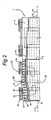
- the oven according to the invention which is illustrated in Figs. 1-3 comprises a housing, which is denoted overall by 1 and is divided into two chambers 3, 4 by means of a partition 2.
- a rotatable drum 5, 6 is arranged in each of these chambers, around which drum the conveyor belt 7 is guided along two helical paths 8 and 9, respectively.
- the conveyor belt enters the oven via the entrance 10 by means of a straight conveyor-belt section 11 and leaves the oven via the exit 12, likewise by means of a straight conveyor-belt section 13.
- the two helical sections 8, 9 are connected by the straight conveyor-belt section 14, which lies at the top.
- the heating means which are denoted overall by 15, are arranged in the top of the housing. These heating means 15 comprise a fan 16 with a spiral casing, which opens out into the air duct, which is denoted overall by 18. The heating elements 19 are situated in this air duct 18.
- This air jet device 20 comprises a plate 21 which bears a series of jet nozzles 22.
- These jet nozzles 22 are situated directly above the curved conveyor belt section 23 of the top turn and also above the straight, connecting conveyor-belt section 14.
- the products which are situated on these conveyor-belt sections 14, 23 are exposed to hot air jets 25 which have a relatively high air velocity. As a result, these products are heated relatively strongly on their surface, so that good browning and, if appropriate, formation of a crispy crust is ensured.
- the air jet device 20 is situated over a quarter of the top turn of the two helical paths 8, 9 and over the straight connecting section 14 of the conveyor belt, which lies at the top.
- the products are exposed to the hot air jets for a certain time as they move through the housing 1, so that the desired effect is ensured.
- a shield plate 26 which prevents the products on the turn below from also being exposed to the direct influence of the hot air jets.
- This shield plate 26 diverts the hot air, in such a manner that it can flow over the turns in a controlled way.
- curved vertical shield plates 27 are also provided, which shield a section of the helical paths 8, 9 on the outer side. As a result, the hot air is forced to flow in the direction of the arrows illustrated in Figs. 1-3 .
- the air then flows back, over and between the turns situated at a lower level, to the inlet side of the fan 16, in such a manner that continuous circulation is ensured.
- the fan is driven by an electric motor 28.
Landscapes
- Life Sciences & Earth Sciences (AREA)
- Engineering & Computer Science (AREA)
- Food Science & Technology (AREA)
- Commercial Cooking Devices (AREA)
- Drying Of Solid Materials (AREA)
- Baking, Grill, Roasting (AREA)
- Encapsulation Of And Coatings For Semiconductor Or Solid State Devices (AREA)
- Nozzles (AREA)
- Liquid Crystal (AREA)
- Fish Paste Products (AREA)
- Treatment Of Fiber Materials (AREA)
Claims (28)
- Ofen mit einem Gehäuse (1), einem Transportband (7) zum Führen von Produkten durch den Innenraum (3, 4) des Gehäuses (1) und Heizmitteln (16 - 19) zum Erhitzen der Produkte (24) im Innenraum (3, 4) des Gehäuses (1) unter Verwendung eines Fluids wie Heißluft und/oder Dampf, wobei sich das Transportband (7) zwischen einem Eingang (10) und einem Ausgang (12) des Gehäuses (1) erstreckt und zwischen diesen beiden Punkten mindestens einer spiralförmigen Bahn (8, 9) folgt, die um eine Trommel (15, 16) vorgesehen ist, die sich um eine vertikale Achse drehen kann, und wobei mindestens eine Fluidstrahlvorrichtung (20) vorgesehen ist, um einen heißen Fluidstrom (25) in Strahlform zu erzeugen, wobei die Fluidstrahlvorrichtung (20) bezüglich mindestens eines Abschnitts des Transportbands (7) so positioniert ist, dass der heiße Fluidstrom (25) in Strahlform auf die auf diesem Abschnitt angeordneten Produkte (24) auftrifft, dadurch gekennzeichnet, dass sich die auf diesem Abschnitt angeordneten Produkte unter der Fluidstrahlvorrichtung (20) hindurchbewegen.
- Ofen nach Anspruch 1, wobei ein gerader Abschnitt (11, 13, 14) des Transportbands (7) jeweils mit den oberen und unteren Windungen verbunden ist, wobei die Fluidstrahlvorrichtung (20) über mindestens einem der geraden Abschnitte (14) angeordnet ist.
- Ofen nach Anspruch 1 oder 2, wobei die Fluidstrahlvorrichtung (20) mindestens über einem gebogenen Abschnitt (23) des Transportbands (7) in der Bahn (8, 9) mit übereinanderliegenden Windungen angeordnet ist.
- Ofen nach Anspruch 3, wobei die Fluidstrahlvorrichtung (20) über mindestens einem Abschnitt (23) der oberen Windung des Transportbands (7) angeordnet ist.
- Ofen nach einem der vorhergehenden Ansprüche, wobei die Fluidstrahlvorrichtung (20) mindestens eine Strahldüse (22) zur Ausgabe eines Strahls Heißluft (25) umfasst.
- Ofen nach Anspruch 5, wobei die Fluidstrahlvorrichtung (20) eine Serie von Strahldüsen (22) umfasst.
- Ofen nach Ansprüchen 3 und 6 oder 4 und 6, wobei die Summe der Flächen der Düsen (22), die in der Nähe der inneren Seite der gebogenen Serie liegen, pro Oberflächeneinheit des darunterliegenden Bands größer als die Summe der Flächen der Düsen (22), die in der Nähe der äußeren Seite der gebogenen Serie liegen, pro Oberflächeneinheit des Bands ist.
- Ofen nach Anspruch 7, wobei die Düsen (22) identisch sind und in der Nähe der inneren Seite der gebogenen Serie kürzer voneinander beabstandet sind als in der Nähe der äußeren Seite der gebogenen Serie.
- Ofen nach Anspruch 8, wobei die Serie von Düsen (22) Reihen umfasst, die sich quer zur Bewegungsrichtung des Transportbands (7) erstrecken.
- Ofen nach einem der vorhergehenden Ansprüche, wobei die Fluidstrahlvorrichtung (20) mindestens eine Platte (21) umfasst, die sich über mindestens einem Abschnitt des Transportbands (7) erstreckt und auf ihrer vom Transportbandabschnitt entfernt gelegenen Seite einen Luftkanal (18) begrenzt und durch die die mindestens eine Strahldüse (22) geht.
- Ofen nach Anspruch 10, wobei sich die Platte (21) über mindestens einen Abschnitt (23) des Transportbands (7) erstreckt, der gebogen in der Bahn (8, 9) mit übereinanderliegenden Windungen läuft, und die Platte (21) eine Serie von Strahldüsen (22) umfasst, die mindestens dem gebogenen Abschnitt (23) des Transportbands (7) folgt.
- Ofen nach Anspruch 11, wobei ein Fluidkanal (18) mit einem Gebläse (16) zum Hindurchzwingen von erhitzter Luft durch den Fluidkanal (18) verbunden ist.
- Ofen nach Anspruch 12, wobei der Fluidkanal (18) über der Bahn (8, 9) mit übereinanderliegenden Windungen angeordnet ist.
- Ofen nach Anspruch 12 oder 11, wobei Heizmittel (19) im Fluidkanal (18) vorliegen.
- Ofen nach einem der Ansprüche 10 - 14, wobei sich die Heizmittel (19) über der Serie von Düsen (22) erstrecken.
- Ofen nach einem der vorhergehenden Ansprüche, wobei das Transportband (7) zwei Bahnen (8, 9) mit übereinanderliegenden Windungen folgt, wobei die oberen Windungen der Bahnen (8, 9) über einen geraden Verbindungstransportbandabschnitt (14) miteinander verbunden sind, und wobei mindestens eine dieser Bahnen mit einer Fluidstrahlvorrichtung (20) versehen ist.
- Ofen nach einem der vorhergehenden Ansprüche, wobei die beiden Bahnen (8, 9) mit übereinanderliegenden Windungen jeweils in einer getrennten Zone (3, 4) mit getrennten Heizmitteln (19) und getrennten Fluidstrahlvorrichtungen (20) angeordnet sind.
- Ofen nach Anspruch 17, wobei die Fluidstrahlvorrichtung (20) in jeder Zone (3, 4) über dem geraden Verbindungstransportbandabschnitt (14) und dem anschließenden gebogenen Förderabschnitt (23) der oberen Windung angeordnet ist.
- Ofen nach Anspruch 18, wobei die Zonen (3, 4) durch eine Trennwand (2) mit einem Durchgang (28) getrennt sind, durch den sich der gerade Verbindungstransportbandabschnitt (14) erstreckt.
- Ofen nach einem der vorhergehenden Ansprüche, wobei das Gehäuse (1) ein Behältnis (29) und eine Kappe (30) umfasst, die bezüglich des Behältnisses (29) zwischen einer offenen Position und einer geschlossenen Position mittels Hebeelementen auf und ab bewegt werden kann.
- Ofen nach Anspruch 20, wobei Stützbeine zum Stützen des Behältnisses (29) vorgesehen sind und die Hebeelemente auf den Stützbeinen angeordnet sind.
- Ofen nach einem der vorhergehenden Ansprüche, wobei das Transportband für einen Fluidstrom durchlässig ist und mindestens ein Schild (26, 27) vorgesehen ist, der bezüglich der Fluidstrahlvorrichtung (20) auf der anderen Seite des Abschnitts des Transportbands (7) angeordnet ist, um das aus der Fluidstrahlvorrichtung kommende Fluid zu mindestens einem der Längsränder des Abschnitts des Transportbands (7) umzulenken.
- Ofen nach Anspruch 22, wobei der Schild (26, 27) zwischen zwei sich übereinander erstreckenden Abschnitten des Transportbands (7) angeordnet ist.
- Ofen nach Anspruch 22 oder 23, wobei der Schild (26, 27) in der Richtung der Außenkontur des Transportbands (7) gesehen schräg nach unten verläuft.
- Ofen nach einem der Ansprüche 22 - 24, wobei der Schild (26, 27) eine Platte umfasst.
- Ofen nach einem der Ansprüche 22 - 25, wobei der Schild (26, 27) mindestens unter einem geraden Abschnitt (14) des Transportbands (7) angeordnet ist.
- Ofen nach einem der Ansprüche 22 - 26, wobei der Schild (26, 27) mindestens unter einem gebogenen Abschnitt (23) des Transportbands (7) angeordnet ist.
- Verfahren zum Betreiben des Ofens nach Anspruch 17, 18 oder 19, bei dem veranlasst wird, dass das Fluid in einer Zone (3) mit einer Geschwindigkeit aus der Fluidstrahlvorrichtung (20) austritt, die sich von der des Fluids unterscheidet, das in der anderen Zone (4) aus der Fluidstrahlvorrichtung (20) austritt.
Priority Applications (1)
| Application Number | Priority Date | Filing Date | Title |
|---|---|---|---|
| DE60200793T DE60200793T3 (de) | 2001-01-05 | 2002-01-04 | Ofen mit Flüssigstrahlvorrichtung |
Applications Claiming Priority (2)
| Application Number | Priority Date | Filing Date | Title |
|---|---|---|---|
| NL1017040A NL1017040C2 (nl) | 2001-01-05 | 2001-01-05 | Oven met luchtstraalinrichting. |
| NL1017040 | 2001-01-05 |
Publications (3)
| Publication Number | Publication Date |
|---|---|
| EP1221575A1 EP1221575A1 (de) | 2002-07-10 |
| EP1221575B1 EP1221575B1 (de) | 2004-07-28 |
| EP1221575B2 true EP1221575B2 (de) | 2010-09-15 |
Family
ID=19772688
Family Applications (1)
| Application Number | Title | Priority Date | Filing Date |
|---|---|---|---|
| EP02075021A Expired - Lifetime EP1221575B2 (de) | 2001-01-05 | 2002-01-04 | Ofen mit Flüssigstrahlvorrichtung |
Country Status (8)
| Country | Link |
|---|---|
| US (1) | US6707010B2 (de) |
| EP (1) | EP1221575B2 (de) |
| AT (1) | ATE272194T1 (de) |
| DE (1) | DE60200793T3 (de) |
| DK (1) | DK1221575T3 (de) |
| ES (1) | ES2225723T3 (de) |
| NL (1) | NL1017040C2 (de) |
| TR (1) | TR200402834T4 (de) |
Cited By (3)
| Publication number | Priority date | Publication date | Assignee | Title |
|---|---|---|---|---|
| US8646383B1 (en) | 2009-09-15 | 2014-02-11 | David Howard | Spiral oven apparatus and method of cooking |
| RU2737163C2 (ru) * | 2015-11-17 | 2020-11-25 | Геа Фуд Сольюшнс Бакел Б.В. | Печь с улучшенной тягой |
| US10912317B2 (en) | 2018-10-19 | 2021-02-09 | John Bean Technologies Ab | Thermal processing apparatus |
Families Citing this family (15)
| Publication number | Priority date | Publication date | Assignee | Title |
|---|---|---|---|---|
| DE20320988U1 (de) * | 2002-12-18 | 2005-08-11 | Jan Entwicklung Gbr (Vertretungsberechtigter Gesellschafter Herr Anderl Johann | Fördervorrichtung für Backwaren |
| SE525675C2 (sv) * | 2003-08-15 | 2005-04-05 | Frigoscandia Equipment Ab | Apparat och metod för behandling av livsmedel med gasformigt medium för beredning och efterföljande torkning |
| US6833533B1 (en) * | 2004-03-12 | 2004-12-21 | Wolfe Electric, Inc. | Air impingement conveyor over |
| NL1027446C2 (nl) * | 2004-11-08 | 2006-05-09 | Stork Titan Bv | Behandelingsinrichting en werkwijze voor het met geconditioneerde lucht behandelen van voedselproducten. |
| NL1028252C2 (nl) * | 2005-02-11 | 2006-08-14 | Cfs Bakel Bv | Werkwijze voor het behandelen van voedselproducten, alsmede lijnoven daarvoor. |
| ES2507506T3 (es) | 2008-04-18 | 2014-10-15 | Gea Food Solutions Bakel B.V. | Horno y proceso para controlar el flujo de aire y las fugas de aire entre dos cámaras |
| ES2879632T3 (es) | 2008-06-19 | 2021-11-22 | Gea Food Solutions Bakel Bv | Horno en espiral con flujo de aire controlado a lo largo de la anchura de la cinta |
| US9220276B2 (en) * | 2011-03-09 | 2015-12-29 | Unitherm Food Systems, Inc. | Airflow pattern for spiral ovens |
| US8895096B2 (en) * | 2011-06-22 | 2014-11-25 | Frito-Lay North America, Inc. | Continuous oven with a cascading conveyor |
| WO2013112052A1 (en) * | 2012-01-27 | 2013-08-01 | Ts Techniek Bv | Dual drum spiral oven |
| US20150150269A1 (en) * | 2012-08-01 | 2015-06-04 | Frito-Lay North America, Inc. | Continuous process and apparatus for making a pita chip |
| JP6494512B2 (ja) * | 2012-09-25 | 2019-04-03 | ジーイーエイ・フード・ソリューションズ・バーケル・ベスローテン・フェンノートシャップ | 蒸煮と燻製との組合せ |
| JP2016503657A (ja) * | 2013-01-04 | 2016-02-08 | ジーイーエイ・フード・ソリューションズ・バーケル・ベスローテン・フェンノートシャップ | 乾燥と燻製との組合せ |
| EP3732985A1 (de) * | 2019-05-02 | 2020-11-04 | Metalquimia, S.A.U. | Auftauanlage und auftauverfahren von rohen gefrorenen fleischprodukten in einem trommeltumbler |
| CN115517555A (zh) * | 2022-09-26 | 2022-12-27 | 广东美的白色家电技术创新中心有限公司 | 烤箱 |
Citations (11)
| Publication number | Priority date | Publication date | Assignee | Title |
|---|---|---|---|---|
| US4344973A (en) † | 1980-11-04 | 1982-08-17 | Blake Anthony A | Method for curing and smoking pork skins to condition them for rendering |
| US4348548A (en) † | 1979-09-11 | 1982-09-07 | Thomas & Betts Corporation | Insulator for covering electrical cables |
| WO1985005546A1 (en) † | 1984-05-31 | 1985-12-19 | Robert Bruce Forney | Continuous feed oven |
| US4563945A (en) † | 1984-11-13 | 1986-01-14 | Stein Associates, Inc. | Heat shield-steam distributor for cooking oven |
| WO1988009124A1 (en) † | 1987-05-28 | 1988-12-01 | Stein, Inc. | Food cooking oven with duct fingers and method |
| EP0558151A1 (de) † | 1992-02-26 | 1993-09-01 | Tetra Laval Food Koppens B.V. | Ofen |
| EP0804878A1 (de) † | 1996-05-03 | 1997-11-05 | Koppens B.V. | Backofen mit Heissluftführung |
| EP0953286A1 (de) † | 1998-04-28 | 1999-11-03 | Stork Titan B.V. | Behandlungsvorrichtung von Nahrungsmitteln mit klimatisierter Luft |
| WO2000013528A1 (en) † | 1998-09-04 | 2000-03-16 | Rhm Technology Limited | Air impingement oven |
| US6065463A (en) † | 1998-10-19 | 2000-05-23 | Sasib Bakery North America, Inc. | Forced convective track oven |
| US6146678A (en) † | 1997-01-04 | 2000-11-14 | Heat And Control, Inc. | Method of cooking food products in an air impingement oven |
Family Cites Families (12)
| Publication number | Priority date | Publication date | Assignee | Title |
|---|---|---|---|---|
| US4631029A (en) * | 1983-12-09 | 1986-12-23 | Lanham Machinery Company, Inc. | Baking oven with heated air distribution-II |
| US4737373A (en) * | 1987-02-11 | 1988-04-12 | Forney Robert B | Cooking and browning system |
| US6041398A (en) * | 1992-06-26 | 2000-03-21 | International Business Machines Corporation | Massively parallel multiple-folded clustered processor mesh array |
| US5243962A (en) * | 1990-01-26 | 1993-09-14 | Stein, Inc. | Cooking oven for slow-cooking of food products |
| US5078120A (en) * | 1990-01-26 | 1992-01-07 | Stein, Inc. | Cooking oven for slow cooking of food products |
| US5189948A (en) * | 1991-02-05 | 1993-03-02 | Beltec International | Low temperature spiral conduction vapor cooker and process |
| US5322007A (en) * | 1991-08-15 | 1994-06-21 | Heat And Control, Inc. | Compact, high-capacity oven |
| US5666876A (en) * | 1991-12-20 | 1997-09-16 | Vos Industries Ltd. | Cooking apparatus |
| US5881636A (en) * | 1998-07-01 | 1999-03-16 | Sweet; Dan | Heat impingement bake oven |
| US6138660A (en) * | 1999-01-06 | 2000-10-31 | Sasib Bakery North America, Inc. | Forced convective track oven having oval spirals |
| JP2002539418A (ja) * | 1999-03-23 | 2002-11-19 | ピッツァ・ハット・インコーポレイテッド | 衝突式オーブン空気流装置及び方法 |
| US6049066A (en) * | 1999-03-26 | 2000-04-11 | Wilson; W. Robert | Concentric air delivery and return oven |
-
2001
- 2001-01-05 NL NL1017040A patent/NL1017040C2/nl not_active IP Right Cessation
-
2002
- 2002-01-04 DK DK02075021T patent/DK1221575T3/da active
- 2002-01-04 EP EP02075021A patent/EP1221575B2/de not_active Expired - Lifetime
- 2002-01-04 ES ES02075021T patent/ES2225723T3/es not_active Expired - Lifetime
- 2002-01-04 DE DE60200793T patent/DE60200793T3/de not_active Expired - Lifetime
- 2002-01-04 TR TR2004/02834T patent/TR200402834T4/xx unknown
- 2002-01-04 AT AT02075021T patent/ATE272194T1/de not_active IP Right Cessation
- 2002-01-04 US US10/035,183 patent/US6707010B2/en not_active Expired - Lifetime
Patent Citations (11)
| Publication number | Priority date | Publication date | Assignee | Title |
|---|---|---|---|---|
| US4348548A (en) † | 1979-09-11 | 1982-09-07 | Thomas & Betts Corporation | Insulator for covering electrical cables |
| US4344973A (en) † | 1980-11-04 | 1982-08-17 | Blake Anthony A | Method for curing and smoking pork skins to condition them for rendering |
| WO1985005546A1 (en) † | 1984-05-31 | 1985-12-19 | Robert Bruce Forney | Continuous feed oven |
| US4563945A (en) † | 1984-11-13 | 1986-01-14 | Stein Associates, Inc. | Heat shield-steam distributor for cooking oven |
| WO1988009124A1 (en) † | 1987-05-28 | 1988-12-01 | Stein, Inc. | Food cooking oven with duct fingers and method |
| EP0558151A1 (de) † | 1992-02-26 | 1993-09-01 | Tetra Laval Food Koppens B.V. | Ofen |
| EP0804878A1 (de) † | 1996-05-03 | 1997-11-05 | Koppens B.V. | Backofen mit Heissluftführung |
| US6146678A (en) † | 1997-01-04 | 2000-11-14 | Heat And Control, Inc. | Method of cooking food products in an air impingement oven |
| EP0953286A1 (de) † | 1998-04-28 | 1999-11-03 | Stork Titan B.V. | Behandlungsvorrichtung von Nahrungsmitteln mit klimatisierter Luft |
| WO2000013528A1 (en) † | 1998-09-04 | 2000-03-16 | Rhm Technology Limited | Air impingement oven |
| US6065463A (en) † | 1998-10-19 | 2000-05-23 | Sasib Bakery North America, Inc. | Forced convective track oven |
Cited By (4)
| Publication number | Priority date | Publication date | Assignee | Title |
|---|---|---|---|---|
| US8646383B1 (en) | 2009-09-15 | 2014-02-11 | David Howard | Spiral oven apparatus and method of cooking |
| RU2737163C2 (ru) * | 2015-11-17 | 2020-11-25 | Геа Фуд Сольюшнс Бакел Б.В. | Печь с улучшенной тягой |
| US11589593B2 (en) | 2015-11-17 | 2023-02-28 | Gea Food Solutions Bakel B.V. | Oven with improved drag |
| US10912317B2 (en) | 2018-10-19 | 2021-02-09 | John Bean Technologies Ab | Thermal processing apparatus |
Also Published As
| Publication number | Publication date |
|---|---|
| ES2225723T3 (es) | 2005-03-16 |
| EP1221575A1 (de) | 2002-07-10 |
| TR200402834T4 (tr) | 2004-12-21 |
| US6707010B2 (en) | 2004-03-16 |
| DE60200793T3 (de) | 2011-06-30 |
| US20020139789A1 (en) | 2002-10-03 |
| EP1221575B1 (de) | 2004-07-28 |
| DK1221575T3 (da) | 2004-08-30 |
| ATE272194T1 (de) | 2004-08-15 |
| DE60200793D1 (de) | 2004-09-02 |
| DE60200793T2 (de) | 2004-12-02 |
| NL1017040C2 (nl) | 2002-07-08 |
Similar Documents
| Publication | Publication Date | Title |
|---|---|---|
| EP1221575B1 (de) | Ofen mit Flüssigstrahlvorrichtung | |
| US6049066A (en) | Concentric air delivery and return oven | |
| CA2224348C (en) | Air impingement oven | |
| CA1319302C (en) | Cooking a food product in a process vapor at progressively varying rates | |
| EP1797758B1 (de) | Kontinuierliches Kochsytem | |
| US4834063A (en) | Food cooking oven with duct fingers and method | |
| AU655294B2 (en) | Compact, high-capacity oven | |
| CN1149951C (zh) | 可变尺寸的快速烤箱 | |
| US4389562A (en) | Conveyor oven | |
| US5934178A (en) | Air impingement oven | |
| EP1149261B1 (de) | Konvektionsofen mit hoher wärmeübertragungsgeschwindigkeit, fettverwaltung und fähigkeit zur rauchverringerung | |
| EP0086568B1 (de) | Wärmebehandlung von Nahrungsmittelprodukten | |
| EP0002784A1 (de) | Ofen mit wechselnder Luftströmung | |
| MXPA05013045A (es) | Horno de coccion de alta velocidad que tiene calentador de incidencia de aire con configuracion mejorada de orificio. | |
| JP2009100774A (ja) | 高速調理装置及び方法 | |
| US20080264623A1 (en) | Ovens, finger ducts therefor, and methods for distributing air in a finger duct | |
| US6065463A (en) | Forced convective track oven | |
| AU680567B2 (en) | Conveyor oven with improved air flow | |
| EP0089762A1 (de) | Ventilator-Speicher-Anordnung | |
| EP1690453B1 (de) | Durchlaufofen zur behandlung von nahrungsmitteln | |
| EP0443330A2 (de) | Backofen | |
| JP2001501480A (ja) | バーナシールド | |
| WO2025125595A1 (en) | Spiral oven and method for treating food products with conditioned air | |
| KR20070030769A (ko) | 컨베이어 오븐 | |
| GB2083738A (en) | Ovens |
Legal Events
| Date | Code | Title | Description |
|---|---|---|---|
| PUAI | Public reference made under article 153(3) epc to a published international application that has entered the european phase |
Free format text: ORIGINAL CODE: 0009012 |
|
| AK | Designated contracting states |
Kind code of ref document: A1 Designated state(s): AT BE CH CY DE DK ES FI FR GB GR IE IT LI LU MC NL PT SE TR |
|
| AX | Request for extension of the european patent |
Free format text: AL;LT;LV;MK;RO;SI |
|
| 17P | Request for examination filed |
Effective date: 20020701 |
|
| AKX | Designation fees paid |
Designated state(s): AT BE CH CY DE DK ES FI FR GB GR IE IT LI LU MC NL PT SE TR |
|
| 17Q | First examination report despatched |
Effective date: 20031121 |
|
| GRAP | Despatch of communication of intention to grant a patent |
Free format text: ORIGINAL CODE: EPIDOSNIGR1 |
|
| GRAS | Grant fee paid |
Free format text: ORIGINAL CODE: EPIDOSNIGR3 |
|
| GRAA | (expected) grant |
Free format text: ORIGINAL CODE: 0009210 |
|
| AK | Designated contracting states |
Kind code of ref document: B1 Designated state(s): AT BE CH CY DE DK ES FI FR GB GR IE IT LI LU MC NL PT SE TR |
|
| REG | Reference to a national code |
Ref country code: GB Ref legal event code: FG4D |
|
| REG | Reference to a national code |
Ref country code: CH Ref legal event code: EP |
|
| REG | Reference to a national code |
Ref country code: IE Ref legal event code: FG4D |
|
| REG | Reference to a national code |
Ref country code: DK Ref legal event code: T3 |
|
| REF | Corresponds to: |
Ref document number: 60200793 Country of ref document: DE Date of ref document: 20040902 Kind code of ref document: P |
|
| REG | Reference to a national code |
Ref country code: CH Ref legal event code: NV Representative=s name: R. A. EGLI & CO. PATENTANWAELTE |
|
| REG | Reference to a national code |
Ref country code: SE Ref legal event code: TRGR |
|
| REG | Reference to a national code |
Ref country code: GR Ref legal event code: EP Ref document number: 20040403293 Country of ref document: GR |
|
| PG25 | Lapsed in a contracting state [announced via postgrant information from national office to epo] |
Ref country code: IT Free format text: LAPSE BECAUSE OF NON-PAYMENT OF DUE FEES Effective date: 20050104 Ref country code: CY Free format text: LAPSE BECAUSE OF FAILURE TO SUBMIT A TRANSLATION OF THE DESCRIPTION OR TO PAY THE FEE WITHIN THE PRESCRIBED TIME-LIMIT Effective date: 20050104 |
|
| PGFP | Annual fee paid to national office [announced via postgrant information from national office to epo] |
Ref country code: DK Payment date: 20050126 Year of fee payment: 4 |
|
| PG25 | Lapsed in a contracting state [announced via postgrant information from national office to epo] |
Ref country code: LU Free format text: LAPSE BECAUSE OF NON-PAYMENT OF DUE FEES Effective date: 20050131 Ref country code: MC Free format text: LAPSE BECAUSE OF NON-PAYMENT OF DUE FEES Effective date: 20050131 |
|
| ET | Fr: translation filed | ||
| REG | Reference to a national code |
Ref country code: ES Ref legal event code: FG2A Ref document number: 2225723 Country of ref document: ES Kind code of ref document: T3 |
|
| PLAQ | Examination of admissibility of opposition: information related to despatch of communication + time limit deleted |
Free format text: ORIGINAL CODE: EPIDOSDOPE2 |
|
| PLBI | Opposition filed |
Free format text: ORIGINAL CODE: 0009260 |
|
| PLBQ | Unpublished change to opponent data |
Free format text: ORIGINAL CODE: EPIDOS OPPO |
|
| PLAQ | Examination of admissibility of opposition: information related to despatch of communication + time limit deleted |
Free format text: ORIGINAL CODE: EPIDOSDOPE2 |
|
| PLAR | Examination of admissibility of opposition: information related to receipt of reply deleted |
Free format text: ORIGINAL CODE: EPIDOSDOPE4 |
|
| PLBQ | Unpublished change to opponent data |
Free format text: ORIGINAL CODE: EPIDOS OPPO |
|
| PLAB | Opposition data, opponent's data or that of the opponent's representative modified |
Free format text: ORIGINAL CODE: 0009299OPPO |
|
| PLAX | Notice of opposition and request to file observation + time limit sent |
Free format text: ORIGINAL CODE: EPIDOSNOBS2 |
|
| 26 | Opposition filed |
Opponent name: STORK TITAN B.V. Effective date: 20050422 |
|
| R26 | Opposition filed (corrected) |
Opponent name: STORK TITAN B.V. Effective date: 20050422 |
|
| NLR1 | Nl: opposition has been filed with the epo |
Opponent name: STORK TITAN B.V. |
|
| NLR1 | Nl: opposition has been filed with the epo |
Opponent name: STORK TITAN B.V. |
|
| PGFP | Annual fee paid to national office [announced via postgrant information from national office to epo] |
Ref country code: IE Payment date: 20051108 Year of fee payment: 5 |
|
| PGFP | Annual fee paid to national office [announced via postgrant information from national office to epo] |
Ref country code: BE Payment date: 20051201 Year of fee payment: 5 |
|
| PLAF | Information modified related to communication of a notice of opposition and request to file observations + time limit |
Free format text: ORIGINAL CODE: EPIDOSCOBS2 |
|
| PLBB | Reply of patent proprietor to notice(s) of opposition received |
Free format text: ORIGINAL CODE: EPIDOSNOBS3 |
|
| PGFP | Annual fee paid to national office [announced via postgrant information from national office to epo] |
Ref country code: AT Payment date: 20051227 Year of fee payment: 5 |
|
| PGFP | Annual fee paid to national office [announced via postgrant information from national office to epo] |
Ref country code: GR Payment date: 20051230 Year of fee payment: 5 |
|
| PGFP | Annual fee paid to national office [announced via postgrant information from national office to epo] |
Ref country code: TR Payment date: 20060102 Year of fee payment: 5 |
|
| PGFP | Annual fee paid to national office [announced via postgrant information from national office to epo] |
Ref country code: FI Payment date: 20060105 Year of fee payment: 5 |
|
| PGFP | Annual fee paid to national office [announced via postgrant information from national office to epo] |
Ref country code: ES Payment date: 20060215 Year of fee payment: 5 |
|
| PGFP | Annual fee paid to national office [announced via postgrant information from national office to epo] |
Ref country code: CH Payment date: 20060426 Year of fee payment: 5 |
|
| PG25 | Lapsed in a contracting state [announced via postgrant information from national office to epo] |
Ref country code: FI Free format text: LAPSE BECAUSE OF NON-PAYMENT OF DUE FEES Effective date: 20070104 Ref country code: IE Free format text: LAPSE BECAUSE OF NON-PAYMENT OF DUE FEES Effective date: 20070104 |
|
| PG25 | Lapsed in a contracting state [announced via postgrant information from national office to epo] |
Ref country code: LI Free format text: LAPSE BECAUSE OF NON-PAYMENT OF DUE FEES Effective date: 20070131 Ref country code: CH Free format text: LAPSE BECAUSE OF NON-PAYMENT OF DUE FEES Effective date: 20070131 |
|
| APBP | Date of receipt of notice of appeal recorded |
Free format text: ORIGINAL CODE: EPIDOSNNOA2O |
|
| APAH | Appeal reference modified |
Free format text: ORIGINAL CODE: EPIDOSCREFNO |
|
| APBQ | Date of receipt of statement of grounds of appeal recorded |
Free format text: ORIGINAL CODE: EPIDOSNNOA3O |
|
| REG | Reference to a national code |
Ref country code: CH Ref legal event code: PL |
|
| REG | Reference to a national code |
Ref country code: DK Ref legal event code: EBP |
|
| REG | Reference to a national code |
Ref country code: IE Ref legal event code: MM4A |
|
| PG25 | Lapsed in a contracting state [announced via postgrant information from national office to epo] |
Ref country code: AT Free format text: LAPSE BECAUSE OF NON-PAYMENT OF DUE FEES Effective date: 20070104 |
|
| BERE | Be: lapsed |
Owner name: *KOPPENS B.V. Effective date: 20070131 |
|
| PG25 | Lapsed in a contracting state [announced via postgrant information from national office to epo] |
Ref country code: BE Free format text: LAPSE BECAUSE OF NON-PAYMENT OF DUE FEES Effective date: 20070131 Ref country code: PT Free format text: LAPSE BECAUSE OF NON-PAYMENT OF DUE FEES Effective date: 20041228 |
|
| PG25 | Lapsed in a contracting state [announced via postgrant information from national office to epo] |
Ref country code: DK Free format text: LAPSE BECAUSE OF NON-PAYMENT OF DUE FEES Effective date: 20070131 |
|
| REG | Reference to a national code |
Ref country code: ES Ref legal event code: FD2A Effective date: 20070105 |
|
| PG25 | Lapsed in a contracting state [announced via postgrant information from national office to epo] |
Ref country code: ES Free format text: LAPSE BECAUSE OF NON-PAYMENT OF DUE FEES Effective date: 20070105 |
|
| PG25 | Lapsed in a contracting state [announced via postgrant information from national office to epo] |
Ref country code: GR Free format text: LAPSE BECAUSE OF NON-PAYMENT OF DUE FEES Effective date: 20070802 |
|
| PG25 | Lapsed in a contracting state [announced via postgrant information from national office to epo] |
Ref country code: TR Free format text: LAPSE BECAUSE OF FAILURE TO SUBMIT A TRANSLATION OF THE DESCRIPTION OR TO PAY THE FEE WITHIN THE PRESCRIBED TIME-LIMIT Effective date: 20040728 |
|
| APBU | Appeal procedure closed |
Free format text: ORIGINAL CODE: EPIDOSNNOA9O |
|
| PUAH | Patent maintained in amended form |
Free format text: ORIGINAL CODE: 0009272 |
|
| STAA | Information on the status of an ep patent application or granted ep patent |
Free format text: STATUS: PATENT MAINTAINED AS AMENDED |
|
| 27A | Patent maintained in amended form |
Effective date: 20100915 |
|
| AK | Designated contracting states |
Kind code of ref document: B2 Designated state(s): AT BE CH CY DE DK ES FI FR GB GR IE IT LI LU MC NL PT SE TR |
|
| REG | Reference to a national code |
Ref country code: ES Ref legal event code: FD2A Effective date: 20070105 |
|
| REG | Reference to a national code |
Ref country code: NL Ref legal event code: T3 |
|
| REG | Reference to a national code |
Ref country code: SE Ref legal event code: RPEO |
|
| REG | Reference to a national code |
Ref country code: DE Ref legal event code: 8570 |
|
| REG | Reference to a national code |
Ref country code: FR Ref legal event code: PLFP Year of fee payment: 15 |
|
| REG | Reference to a national code |
Ref country code: FR Ref legal event code: PLFP Year of fee payment: 16 |
|
| REG | Reference to a national code |
Ref country code: FR Ref legal event code: PLFP Year of fee payment: 17 |
|
| PGFP | Annual fee paid to national office [announced via postgrant information from national office to epo] |
Ref country code: FR Payment date: 20210120 Year of fee payment: 20 Ref country code: NL Payment date: 20210120 Year of fee payment: 20 |
|
| PGFP | Annual fee paid to national office [announced via postgrant information from national office to epo] |
Ref country code: GB Payment date: 20210122 Year of fee payment: 20 Ref country code: DE Payment date: 20210120 Year of fee payment: 20 Ref country code: SE Payment date: 20210122 Year of fee payment: 20 |
|
| REG | Reference to a national code |
Ref country code: DE Ref legal event code: R071 Ref document number: 60200793 Country of ref document: DE |
|
| REG | Reference to a national code |
Ref country code: NL Ref legal event code: MK Effective date: 20220103 |
|
| REG | Reference to a national code |
Ref country code: GB Ref legal event code: PE20 Expiry date: 20220103 |
|
| PG25 | Lapsed in a contracting state [announced via postgrant information from national office to epo] |
Ref country code: GB Free format text: LAPSE BECAUSE OF EXPIRATION OF PROTECTION Effective date: 20220103 |