EP1222409B1 - Integrierte konsole und endverschlussplatte für eine luftfeder - Google Patents
Integrierte konsole und endverschlussplatte für eine luftfeder Download PDFInfo
- Publication number
- EP1222409B1 EP1222409B1 EP00978264A EP00978264A EP1222409B1 EP 1222409 B1 EP1222409 B1 EP 1222409B1 EP 00978264 A EP00978264 A EP 00978264A EP 00978264 A EP00978264 A EP 00978264A EP 1222409 B1 EP1222409 B1 EP 1222409B1
- Authority
- EP
- European Patent Office
- Prior art keywords
- bracket
- wall
- end plate
- upstanding
- combination
- Prior art date
- Legal status (The legal status is an assumption and is not a legal conclusion. Google has not performed a legal analysis and makes no representation as to the accuracy of the status listed.)
- Expired - Lifetime
Links
Images



Classifications
-
- B—PERFORMING OPERATIONS; TRANSPORTING
- B60—VEHICLES IN GENERAL
- B60G—VEHICLE SUSPENSION ARRANGEMENTS
- B60G11/00—Resilient suspensions characterised by arrangement, location or kind of springs
- B60G11/26—Resilient suspensions characterised by arrangement, location or kind of springs having fluid springs only, e.g. hydropneumatic springs
- B60G11/28—Resilient suspensions characterised by arrangement, location or kind of springs having fluid springs only, e.g. hydropneumatic springs characterised by means specially adapted for attaching the spring to axle or sprung part of the vehicle
-
- F—MECHANICAL ENGINEERING; LIGHTING; HEATING; WEAPONS; BLASTING
- F16—ENGINEERING ELEMENTS AND UNITS; GENERAL MEASURES FOR PRODUCING AND MAINTAINING EFFECTIVE FUNCTIONING OF MACHINES OR INSTALLATIONS; THERMAL INSULATION IN GENERAL
- F16F—SPRINGS; SHOCK-ABSORBERS; MEANS FOR DAMPING VIBRATION
- F16F9/00—Springs, vibration-dampers, shock-absorbers, or similarly-constructed movement-dampers using a fluid or the equivalent as damping medium
- F16F9/02—Springs, vibration-dampers, shock-absorbers, or similarly-constructed movement-dampers using a fluid or the equivalent as damping medium using gas only or vacuum
- F16F9/04—Springs, vibration-dampers, shock-absorbers, or similarly-constructed movement-dampers using a fluid or the equivalent as damping medium using gas only or vacuum in a chamber with a flexible wall
- F16F9/0454—Springs, vibration-dampers, shock-absorbers, or similarly-constructed movement-dampers using a fluid or the equivalent as damping medium using gas only or vacuum in a chamber with a flexible wall characterised by the assembling method or by the mounting arrangement, e.g. mounting of the membrane
-
- B—PERFORMING OPERATIONS; TRANSPORTING
- B60—VEHICLES IN GENERAL
- B60G—VEHICLE SUSPENSION ARRANGEMENTS
- B60G2202/00—Indexing codes relating to the type of spring, damper or actuator
- B60G2202/10—Type of spring
- B60G2202/15—Fluid spring
- B60G2202/152—Pneumatic spring
-
- B—PERFORMING OPERATIONS; TRANSPORTING
- B60—VEHICLES IN GENERAL
- B60G—VEHICLE SUSPENSION ARRANGEMENTS
- B60G2202/00—Indexing codes relating to the type of spring, damper or actuator
- B60G2202/40—Type of actuator
- B60G2202/41—Fluid actuator
- B60G2202/412—Pneumatic actuator
-
- B—PERFORMING OPERATIONS; TRANSPORTING
- B60—VEHICLES IN GENERAL
- B60G—VEHICLE SUSPENSION ARRANGEMENTS
- B60G2204/00—Indexing codes related to suspensions per se or to auxiliary parts
- B60G2204/10—Mounting of suspension elements
- B60G2204/12—Mounting of springs or dampers
- B60G2204/126—Mounting of pneumatic springs
-
- B—PERFORMING OPERATIONS; TRANSPORTING
- B60—VEHICLES IN GENERAL
- B60G—VEHICLE SUSPENSION ARRANGEMENTS
- B60G2204/00—Indexing codes related to suspensions per se or to auxiliary parts
- B60G2204/10—Mounting of suspension elements
- B60G2204/20—Mounting of accessories, e.g. pump, compressor
- B60G2204/201—Mounting of accessories, e.g. pump, compressor of fluid lines
-
- B—PERFORMING OPERATIONS; TRANSPORTING
- B60—VEHICLES IN GENERAL
- B60G—VEHICLE SUSPENSION ARRANGEMENTS
- B60G2206/00—Indexing codes related to the manufacturing of suspensions: constructional features, the materials used, procedures or tools
- B60G2206/01—Constructional features of suspension elements, e.g. arms, dampers, springs
- B60G2206/40—Constructional features of dampers and/or springs
- B60G2206/42—Springs
- B60G2206/424—Plunger or top retainer construction for bellows or rolling lobe type air springs
Definitions
- the invention relates to an air springs and in particular to an air spring in which the end plate which is mounted opposite of the piston is formed integrally as a one-piece plastic member combining the end plate with a mounting bracket which is hollow to form an auxiliary fluid chamber. More particularly, the invention relates to such a combination end plate and mounting bracket which is mounted to a supporting structure which is oriented perpendicular to the direction of orientation of the corresponding structure on which the piston is mounted.
- EP-A-0 264 573 discloses an air spring including an end cap member and an opposed piston member.
- the piston member has a generally cylindrical side wall terminating in an upper open end and having an exterior annular clamping surface formed with a plurality of grooves.
- the end cap member has a cup-shaped configuration with a cylindrical side wall terminating in a closed end wall and an open end which communicates with the interior of flexible sleeve.
- Air actuators and in particular air springs consist of a pair of spaced end members and an intervening flexible sleeve or bellows formed of an elastomeric material to form an internal pressurized fluid chamber. These devices are used for many applications. One main applications is between spaced components of a vehicle for absorbing road shock or supporting parts of machinery and equipment on which shock forces are continually imparted, and for regulating and maintaining the spacing between the two spaced components of various pieces of equipment including vehicles.
- These air springs usually consist of an upper end member or end plate which is usually attached to the underside of a bracket or support member, and an opposite piston member which is usually mounted to the top surface of a second supporting structure spaced from the first supporting structure.
- Patent No. 5,326,082 shows one type of air spring in which an auxiliary chamber is formed within the interior of the piston member as well as within the interior of the end cap or end member, both of which are formed of a plastic material to reduce corrosion and facilitate the production of the end members.
- the mounting surfaces are parallel to each other and no structure is provided for securing one of the end members, and in particular the end member opposite of the piston, to a mounting surface perpendicular to that of the piston mounting surface.
- the object of the invention is to provide an air spring which can be mounted to a structure extending perpendicularly to the mounting surface of the opposite structural member on which the piston is mounted, and which has an increased internal volume of the fluid chamber while not substantially increasing the size of the air spring.
- Fig. 1 shows the integral bracket and end mounting plate of the present invention incorporated within an air spring or air actuator indicated generally at 1.
- Air spring 1 has a pair of end members, one of which is a piston 2 which is mounted in an upright position on a support plate 3.
- Support plate 3 could be mounted on the end of a trailing arm, axle plate or similar portion of a vehicle, or any spaced support structures of a piece of equipment with which air spring 1 can be used.
- the unique bracket and end mounting plate combination of the present invention is indicated generally at 5, and is shown secured to one open end of a flexible sleeve or bellows 6, usually formed of an elastomeric material, which forms an internal fluid pressure chamber 7 (Fig. 2).
- Combination 5 is shown mounted to a vertical side or web wall 9 of a U-shaped beam 10, which could be one of the chassis frame members of a vehicle.
- Beam 10 could be other types of supporting structures of a vehicle or other equipment, but in accordance with one of the features of the invention, it will have a mounting surface such as web wall 9, which generally aligns with the longitudinal axis 11 of air spring 1 and perpendicular to the mounting surface 12 of support plate 3 on which piston 2 is mounted.
- Fig. 2 shows in more detail the structure of the end mounting plate and bracket 5 of the present invention.
- the end plate portion of combination 5 is indicated generally at 13, and has an annular disc-shaped configuration and is formed with a stepped outer peripheral flange 14.
- a pressure clamp 15 sealingly clamps bead area 16 of sleeve 6 against flange 14 to form a fluid tight sealing engagement with the end plate.
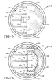
- End plate 13 further includes a generally semi-circular shaped planar wall 18 (Figs. 2 and 7), and a generally semi-circular shaped opening 19.
- Bracket portion 22 of the bracket and end mounting plate combination 5 includes a generally planar upstanding wall 23 which has a somewhat triangular-shaped configuration as shown in Fig. 3, and which includes a plurality of spaced parallel reinforcing ribs 24 formed integrally on its outer surface and extending throughout the vertical length thereof.
- a half dome-shaped enclosure wall 26 together with upstanding wall 23 forms an auxiliary air chamber 27 which is located above end plate 13 and in fluid communication with main pressure chamber 7.
- a plurality of ribs 25 extend along the inside surface of wall 23 and continue along the inside surface of enclosure wall 26 (Figs. 2, 6 and 7) within fluid chamber 27.
- a plurality of reinforcing ribs 29 and 30 also extend along the top and bottom surfaces, respectively, of semi-circular wall 18 of end plate 13 to provide for an extremely strong and rigid mounting bracket and end plate structure.
- a pair of mounting bosses 31 are formed integrally with upstanding wall 23 and portions of enclosure wall 26 for securing bracket and end mounting plate 5 to flange wall 9 (Figs. 1 and 6).
- Bosses 31 preferably are formed with a hollow bore 33 through which bolts 34 extend for clamping wall 23 tightly against wall 9 by a nut 35 and a rear retaining washer 36.
- Other types of attachment means and fasteners can be used for securing wall 23 generally flush against wall 9 than bolts 34 shown in the drawings.
- a rigid conduit 38 is formed integrally with planar wall 23, preferably adjacent upper end 39 of wall 23 where it merges with enclosure wall 26.
- Conduit 38 has a hollow bore 40 and is adapted to be connected to a fluid supply line 41 which is connected to a compressor or other fluid pressure device for regulating the flow of air into and out of fluid chambers 7 and 27.
- Fluid supply line 41 may be secured to conduit 38 by a clamp ring 43, and preferably a plurality of O-rings 44 provide sealing engagement between conduit 38 and fluid supply line 41.
- Conduit 38 preferably extends through an opening 42 formed in web wall 9.
- Combination end plate and mounting bracket 5 preferably is formed of a high strength plastic material, or other types of lightweight materials which are well known in the air spring industry to provide for a corrosion resistance structure.
- the improved integral bracket and end mounting plate for air spring is simplified, provides an effective, safe, inexpensive, and efficient device which achieves all the enumerated objectives, provides for eliminating difficulties encountered with prior devices, and solves problems and obtains new results in the art.
Landscapes
- Engineering & Computer Science (AREA)
- General Engineering & Computer Science (AREA)
- Mechanical Engineering (AREA)
- Fluid-Damping Devices (AREA)
- Vehicle Body Suspensions (AREA)
- Combined Devices Of Dampers And Springs (AREA)
Claims (20)
- Luftfeder (1), einschließlich:a) ein erstes und zweites Endglied, die ausgelegt sind, um an beabstandeten Stellen an einem ersten bzw. zweiten Aufbau befestigt zu werden, von denen mindestens eines in einer generell axialen Richtung in Bezug zum anderen beweglich ist;b) ein flexibler Balg (6), der ein erstes und zweites offenes Ende besitzt, die abdichtend mit dem ersten bzw. zweiten Endglied unter Ausbildung einer Hauptströmungskammer (7) innerhalb des Balges (6) zum Aufnehmen eines unter Druck stehenden Fluids in Eingriff stehen; undc) das erste Endglied umfasst eine Endplatte (13), die eine äußere Umfangskante besitzt, welche abdichtend mit dem ersten offenen Ende des flexiblen Balges (6) und einer aufrecht stehenden Konsole verbunden ist, die integral mit der Endplatte (13) ausgebildet ist und sich davon nach außen erstreckt, wobei die Konsole einen inneren Hohlraum besitzt, der eine Hilfsströmungskammer (27) vorsieht, die außerhalb der Endplatte (13) angeordnet ist und in Strömungsmittelverbindung mit der Hauptströmungskammer (7) steht, wobei die Konsole ferner ein Befestigungsmittel zum Befestigen der Konsole am ersten Aufbau umfasst.
- Luftfeder (1) nach Anspruch 1, bei der die Konsole eine senkrecht generell ebene Wand besitzt, die ausgelegt ist, um gegen den ersten Aufbau anzugrenzen, und wobei die Endplatte (13) eine halbkreisförmige, generell ebene Wand (18) besitzt, die sich generell senkrecht in Bezug zur senkrechten Wand (23) der Konsole erstreckt.
- Luftfeder (1) nach Anspruch 2, bei der sich ein starres Rohr von der senkrechten ebenen Wand der Konsole nach außen erstreckt parallel zur halbkreisförmigen Wand (18) der Endplatte (13), und wobei das starre Rohr hohl ist und in Strömungsmittelverbindung mit der Hilfsströmungskammer (27) steht.
- Luftfeder (1) nach Anspruch 2, bei der die Konsole ferner eine generell halbkuppelförmige Wand umfasst, die mit der aufrecht stehenden bzw. senkrechten Wand (23) verbunden ist und die Hilfskammer (27) dazwischen bildet.
- Luftfeder (1) nach Anspruch 2, bei der das Befestigungsmittel mindestens zwei hohle Lochplatten (31) zur Aufnahme von Befestigungsbolzen oder Schrauben (34) dadurch umfasst.
- Luftfeder (1) nach Anspruch 1, bei der die Endwand und die Konsole als integrales einstückiges Teil aus einem hochfesten Kunststoffmaterial geformt sind.
- Luftfeder (1) nach Anspruch 4, bei der sich eine Vielzahl von Verstärkungsrippen entlang der halbkuppelförmigen Wand und der aufrecht stehenden Wand (23) der Konsole innerhalb der Hilfskammer (27) erstrecken.
- Kombination von einem ersten und zweiten Tragaufbau, die voneinander beabstandet sind, und einem Strömungsmittel betätigten Glied, das ein erstes und ein zweites Endglied und einen flexiblen Balg (6) besitzt, der sich zwischen den Endgliedern unter Ausbildung einer inneren Hauptströmungskammer (7) erstreckt, wobei jedes Endglied entsprechend mit einem der Tragaufbauten verbunden ist, und wobei das erste Endglied eine Endplatte (13) und eine aufrecht stehenden Konsole oder Halterung umfasst, die eine Hilfsströmungskammer (27) über der Endplatte (13) ausbildet und in Strömungsverbindung mit der Hauptströmungskammer (7) über eine Öffnung steht, die in der Endplatte (13) ausgebildet ist, und wobei die Konsole eine aufrecht stehende Wand (23) besitzt, die sich generell parallel zu einer Längsachse des flexiblen Balges (6) erstreckt und Befestigungen umfasst zum Befestigen der aufrecht stehenden Wand (23) an dem ersten Tragaufbau.
- Kombination nach Anspruch 8, bei der die aufrecht stehende Wand (23) der Konsole einen generell rechten Winkel zur Endplatte (13) ausbildet.
- Kombination nach Anspruch 8, bei der die Befestigungen mindestens ein Paar Befestigungselemente umfassen, die sich zwischen dem ersten Tragaufbau und der aufrecht stehenden Wand (23) der Konsole erstrecken.
- Kombination nach Anspruch 10, bei dem ein Lochplattenpaar an der Konsole ausgebildet ist, und wobei sich ein Schraubenpaar (34) durch die Löscher, die im ersten Tragaufbau ausgebildet sind und durch die Lochplatten (31) unter Ausbildung der Befestigungen erstreckt.
- Kombination nach Anspruch 8, bei dem der erste Tragaufbau mindestens einen L-förmigen Abschnitt umfasst, und bei der die Endplatte (13) und die senkrechte Wand (23) der Konsole gegen einen entsprechenden Teil des L-förmigen Abschnitts angrenzen.
- Kombination nach Anspruch 8, bei dem eine Lufteinlassöffnung in der senkrechten Wand (23) der Konsole ausgebildet und zu einer Öffnung ausgerichtet ist, die in einem senkrechten Abschnitt des ersten Tragaufbaus ausgebildet ist.
- Kombination nach Anspruch 8, bei dem die Endplatte ringförmig ist und in einer äußeren Umfangskante endet, und wobei der flexible Balg (6) abdichtend an der Außenkante der Endplatte (13) festgeklemmt ist, und wobei die Endplatte (13) mit einer generell halbkreisförmigen Öffnung (19) ausgebildet ist, die zur Hauptströmungskammer (7) ausgerichtet ist.
- Integrale einstückige Kombination (5) von Endplatte und Befestigungskonsole zum abdichtenden Eingriff mit einem offenen Ende eines flexiblen Balges (6) eines Luftstellgliedes und zur Befestigung eines Endes des Luftstellgliedes an einem Tragaufbau, wobei die Befestigungskonsole eine senkrechte Wand (23) besitzt, die sich generell senkrecht zur Endplatte (13) und einer Umhüllungswand (26) erstreckt, die eine Hilfsströmungsmittelkammer (27) mit der senkrechten Wand (23) bildet, und wobei die Hilfskammer (27) über der Endplatte (13) und innerhalb der Befestigungskonsole angeordnet ist, und wobei die Befestigungen die senkrechte Wand (23) mit dem Tragaufbau verbinden.
- Kombination (5) nach Anspruch 15, bei der sich eine Vielzahl von Verstärkungsrippen (24) entlang der senkrechten Wand (23) und der Umhüllungswand (26) innerhalb der Hilfsströmungsmittelkammer (27) erstrecken.
- Kombination (5) nach Anspruch 15, bei der die Endplatte (13) generell ringförmig und mit einer generell halbkreisförmigen Endwand (18) und einer generell halbkreisförmigen Öffnung (19) ausgebildet ist, die der Strömungsmittelverbindung zwischen der Hilfsströmungsmittelkammer (27) und der Hauptströmungsmittelkammer (7) dient.
- Kombination (5) nach Anspruch 17, bei der die Endplatte (13) in einem gestuften ringförmigen Umfangsflansch (14) endet und bei der eine Ringklemme (15) am Endflansch befestigt ist, um den Dichtungseingriff mit einem offenen Ende des flexiblen Balges (6) vorzusehen.
- Kombination (5) nach Anspruch 15, bei der sich ein Strömungsmittelrohr (38) von der senkrechten Wand (23) der Konsole zur Verbindung mit einem Vorrat an unter Druck stehenden Strömungsmittel (41) nach außen erstreckt.
- Kombination (5) nach Anspruch 15, bei der die Umhüllungswand (26) eine generell halbkuppelförmige Wand darstellt.
Applications Claiming Priority (5)
| Application Number | Priority Date | Filing Date | Title |
|---|---|---|---|
| US16097799P | 1999-10-22 | 1999-10-22 | |
| US160977P | 1999-10-22 | ||
| US47864100A | 2000-01-06 | 2000-01-06 | |
| US478641 | 2000-01-06 | ||
| PCT/US2000/029148 WO2001033101A1 (en) | 1999-10-22 | 2000-10-20 | Integral bracket and end mounting plate for air spring |
Publications (2)
| Publication Number | Publication Date |
|---|---|
| EP1222409A1 EP1222409A1 (de) | 2002-07-17 |
| EP1222409B1 true EP1222409B1 (de) | 2004-12-22 |
Family
ID=26857403
Family Applications (1)
| Application Number | Title | Priority Date | Filing Date |
|---|---|---|---|
| EP00978264A Expired - Lifetime EP1222409B1 (de) | 1999-10-22 | 2000-10-20 | Integrierte konsole und endverschlussplatte für eine luftfeder |
Country Status (9)
| Country | Link |
|---|---|
| US (2) | US20020030312A1 (de) |
| EP (1) | EP1222409B1 (de) |
| JP (1) | JP4693323B2 (de) |
| AU (1) | AU758199B2 (de) |
| BR (1) | BR0015242B1 (de) |
| CA (1) | CA2388555C (de) |
| DE (1) | DE60016952T2 (de) |
| MX (1) | MXPA02003691A (de) |
| WO (1) | WO2001033101A1 (de) |
Cited By (1)
| Publication number | Priority date | Publication date | Assignee | Title |
|---|---|---|---|---|
| DE102017004115A1 (de) | 2017-04-27 | 2018-10-31 | Daimler Ag | Luftfederdeckel |
Families Citing this family (19)
| Publication number | Priority date | Publication date | Assignee | Title |
|---|---|---|---|---|
| AU784814B2 (en) | 2000-08-09 | 2006-06-29 | Bfs Diversified Products, Llc | Integrated air spring |
| US6698730B2 (en) * | 2001-10-04 | 2004-03-02 | Bfs Diversified Products, Llc | Dual rate air spring |
| AU2003262787A1 (en) * | 2002-08-21 | 2004-03-11 | Delphi Technologies, Inc. | Controlled truck cab suspension |
| WO2004018242A2 (en) * | 2002-08-21 | 2004-03-04 | Delphi Technologies, Inc. | Controlled truck cab suspension system |
| US7497423B2 (en) * | 2004-11-04 | 2009-03-03 | Bfs Diversified Products, Llc | Extensible end member for gas spring assembly |
| US7325794B2 (en) | 2005-06-06 | 2008-02-05 | Bfs Diversified Products, Llc | Air spring assembly and method |
| US7404547B2 (en) * | 2005-07-27 | 2008-07-29 | Bfs Diversified Products, Llc | Multi-component end member assembly and air spring assembly including the same |
| US7401770B1 (en) * | 2007-05-24 | 2008-07-22 | Ganswich William G | Stabilizer for a vehicle with suspension springs |
| DE102010016768A1 (de) * | 2010-05-04 | 2011-11-10 | Contitech Luftfedersysteme Gmbh | Luftfederanordnung für ein Nutzfahrzeug |
| CN102562902B (zh) * | 2012-02-22 | 2015-12-16 | 喜临门家具股份有限公司 | 一种环接式气压弹簧 |
| EP2775162B1 (de) | 2013-03-08 | 2019-10-30 | ContiTech USA, Inc. | Verbundstoffwulstplatte und Luftfeder damit |
| GB2514536B (en) * | 2013-03-18 | 2017-05-03 | Alexander Dennis Ltd | Suspension arrangement |
| DK178600B1 (da) * | 2014-09-18 | 2016-08-08 | Hbn Teknik As | Monteringssystem til montering af affjedringskomponenter på et køretøj |
| DE102015108519B3 (de) * | 2015-05-29 | 2016-07-28 | Saf-Holland Gmbh | Stützeinheit |
| USD807796S1 (en) | 2016-03-18 | 2018-01-16 | Hendrickson Usa, L.L.C. | Load cushion |
| DE102017202094A1 (de) * | 2017-02-09 | 2018-08-09 | Contitech Luftfedersysteme Gmbh | Luftfeder mit einem Kunststoffdeckel |
| US11472247B2 (en) | 2019-10-01 | 2022-10-18 | Firestone Industrial Products Company, Llc | Mounting bracket assemblies as well as suspension assemblies, kits and methods including same |
| WO2023023141A1 (en) * | 2021-08-17 | 2023-02-23 | ILJIN USA Corporation | Synthetic elastomeric air spring without reinforcing fibers |
| CA3228783A1 (en) * | 2021-08-27 | 2023-03-02 | Damon Delorenzis | Damping air spring for heavy-duty vehicle axle/suspension systems |
Family Cites Families (35)
| Publication number | Priority date | Publication date | Assignee | Title |
|---|---|---|---|---|
| US532139A (en) | 1895-01-08 | Eot water boiler | ||
| NL220888A (de) | 1956-10-02 | |||
| US3850437A (en) | 1972-11-17 | 1974-11-26 | Gen Motors Corp | Leveling system with a single offset mounted air spring |
| US3876193A (en) | 1972-11-29 | 1975-04-08 | Gen Motors Corp | Boot controlled unitary valve and seal assembly |
| US4386791A (en) | 1981-07-06 | 1983-06-07 | Ford Motor Company | Actively controlled suspension system and height sensor |
| FR2523246A1 (fr) | 1982-03-11 | 1983-09-16 | Dunlop Sa | Dispositifs a fluide sous pression, tels que verins, ressorts et/ou amortisseurs de chocs et/ou de vibrations |
| US4506910A (en) | 1982-09-21 | 1985-03-26 | Granning Suspensions, Inc. | Automotive vehicle suspension |
| US4564177A (en) | 1983-04-21 | 1986-01-14 | The Firestone Tire & Rubber Company | Clamp for non-beaded pneumatic assemblies |
| US4934667A (en) | 1986-08-13 | 1990-06-19 | General Motors Corporation | Air spring damper for vehicle suspension |
| DE3766067D1 (de) * | 1986-09-24 | 1990-12-13 | Firestone Tire & Rubber Co | Luftfeder mit innerem dichtungsring und verfahren zu dessen montage. |
| US4787607A (en) | 1986-09-24 | 1988-11-29 | The Firestone Tire & Rubber Company | Air spring having internal sealing band and method of installing same |
| JP2662218B2 (ja) | 1987-04-03 | 1997-10-08 | 株式会社ブリヂストン | 空気ばね |
| US4796870A (en) | 1987-05-18 | 1989-01-10 | The Firestone Tire & Rubber Company | Suspension system for vehicles containing combination isolator mount and air spring closure |
| US4787606A (en) | 1987-06-17 | 1988-11-29 | The Firestone Tire & Rubber Company | Beadless air spring |
| US4817922A (en) | 1987-10-23 | 1989-04-04 | The Goodyear Tire & Rubber Company | Airspring height sensor |
| US4798369A (en) | 1987-11-03 | 1989-01-17 | The Firestone Tire & Rubber Company | Ultrasonic air spring system |
| US4923210A (en) * | 1989-03-28 | 1990-05-08 | Heider Merle J | Suspension and leveling system for a vehicle |
| US5180145A (en) | 1991-05-30 | 1993-01-19 | Bridgestone Corporation | Vibration damping device |
| CA2085068A1 (en) | 1991-12-17 | 1993-06-18 | John L. Vaphiadis | Counterbalance actuator having an extended stroke |
| US5326082A (en) | 1992-06-10 | 1994-07-05 | Bridgestone/Firestone, Inc. | Self locking, snap mounted attachment device |
| DE4230249C2 (de) | 1992-09-10 | 1995-11-23 | Continental Ag | Luftfeder für Fahrzeuge mit einem elastomeren Rollbalg und einem Abrollkolben |
| US5346247A (en) * | 1993-05-14 | 1994-09-13 | Reyco Industries, Inc. | Truck air ride suspension |
| US5382006A (en) | 1993-09-29 | 1995-01-17 | The Goodyear Tire & Rubber Company | Airspring piston and airspring assembly |
| US5535994A (en) | 1993-11-30 | 1996-07-16 | The Goodyear Tire & Rubber Company | Composite air spring piston |
| JPH07301280A (ja) * | 1994-03-10 | 1995-11-14 | Toyoda Gosei Co Ltd | 防振支持装置 |
| JPH08270697A (ja) * | 1995-03-28 | 1996-10-15 | Toyoda Gosei Co Ltd | 防振支持装置 |
| US5671907A (en) | 1995-12-07 | 1997-09-30 | The Goodyear Tire & Rubber Company | Method of attachment of flexible member to stamped steel piston |
| DE29619081U1 (de) | 1996-11-04 | 1997-01-09 | ContiTech Luftfedersysteme GmbH, 30165 Hannover | Rollbalg-Luftfeder |
| US5887881A (en) | 1997-08-11 | 1999-03-30 | The Boler Company. | Leaf spring attachment member |
| US6062579A (en) | 1998-04-07 | 2000-05-16 | Fortier; Paul Henri | Retrofittable suspension system for the rear axle of a vehicle |
| JP4143782B2 (ja) * | 1999-03-31 | 2008-09-03 | 株式会社日立製作所 | エアサスペンション装置 |
| AU4213099A (en) * | 1999-05-28 | 2000-12-18 | Goodyear Tire And Rubber Company, The | Air spring upper retainer |
| US6109598A (en) | 1999-06-29 | 2000-08-29 | Bridgestone/Firestone, Inc. | Air spring bumper utilizing a combination of materials |
| US6402128B1 (en) * | 2000-01-31 | 2002-06-11 | The Goodyear Tire And Rubber Company | Air spring with lateral restraint and axial control |
| US6416044B1 (en) * | 2000-05-16 | 2002-07-09 | International Truck Intellectual Property Company, L.L.C. | Compressible fluid suspension system |
-
2000
- 2000-10-20 BR BRPI0015242-0A patent/BR0015242B1/pt not_active IP Right Cessation
- 2000-10-20 WO PCT/US2000/029148 patent/WO2001033101A1/en not_active Ceased
- 2000-10-20 EP EP00978264A patent/EP1222409B1/de not_active Expired - Lifetime
- 2000-10-20 MX MXPA02003691A patent/MXPA02003691A/es active IP Right Grant
- 2000-10-20 CA CA002388555A patent/CA2388555C/en not_active Expired - Fee Related
- 2000-10-20 DE DE60016952T patent/DE60016952T2/de not_active Expired - Lifetime
- 2000-10-20 AU AU15743/01A patent/AU758199B2/en not_active Ceased
- 2000-10-20 JP JP2001534951A patent/JP4693323B2/ja not_active Expired - Fee Related
-
2001
- 2001-11-21 US US09/990,412 patent/US20020030312A1/en not_active Abandoned
- 2001-11-27 US US09/995,105 patent/US6513798B2/en not_active Expired - Lifetime
Cited By (1)
| Publication number | Priority date | Publication date | Assignee | Title |
|---|---|---|---|---|
| DE102017004115A1 (de) | 2017-04-27 | 2018-10-31 | Daimler Ag | Luftfederdeckel |
Also Published As
| Publication number | Publication date |
|---|---|
| BR0015242B1 (pt) | 2009-05-05 |
| DE60016952T2 (de) | 2005-06-16 |
| WO2001033101A1 (en) | 2001-05-10 |
| EP1222409A1 (de) | 2002-07-17 |
| AU758199B2 (en) | 2003-03-20 |
| US20020109275A1 (en) | 2002-08-15 |
| DE60016952D1 (de) | 2005-01-27 |
| MXPA02003691A (es) | 2005-09-08 |
| JP2003513213A (ja) | 2003-04-08 |
| JP4693323B2 (ja) | 2011-06-01 |
| AU1574301A (en) | 2001-05-14 |
| US6513798B2 (en) | 2003-02-04 |
| US20020030312A1 (en) | 2002-03-14 |
| CA2388555C (en) | 2009-02-17 |
| BR0015242A (pt) | 2002-07-16 |
| CA2388555A1 (en) | 2001-05-10 |
Similar Documents
| Publication | Publication Date | Title |
|---|---|---|
| CA2388555C (en) | Integral bracket and end mounting plate for air spring | |
| US6250613B1 (en) | Non-metallic spacer for air spring assembly | |
| US10137749B2 (en) | Air spring with damping characteristics for heavy-duty vehicles | |
| US8061691B2 (en) | Piston and gas spring assembly including same | |
| EP0969223B1 (de) | Schnappuffer für Luftfeder | |
| US20060006590A1 (en) | Vehicle suspension system | |
| US20040032065A1 (en) | Variable rate air spring assembly | |
| CA2455862A1 (en) | Pedestal mounted full reservoir air spring piston | |
| US10150345B2 (en) | Gas spring end member as well as gas spring assembly and suspension system including same | |
| US4635745A (en) | Vehicle air suspension | |
| EP0865583A1 (de) | Methode zur befestigung eines flexiblen gliedes an einem gepressten stahlkolben | |
| US20040021258A1 (en) | Volume reducing bead plate for air spring | |
| WO2001051300A1 (en) | Pneumatic suspension system for vehicles | |
| GB2084692A (en) | Rolling diaphragm gas springs combined with shock absorbers | |
| US20230105366A1 (en) | Mounting bracket assemblies as well as suspension assemblies, kits and methods including same | |
| AU2014203084B2 (en) | Gas spring end member as well as gas spring assembly and suspension system including same |
Legal Events
| Date | Code | Title | Description |
|---|---|---|---|
| PUAI | Public reference made under article 153(3) epc to a published international application that has entered the european phase |
Free format text: ORIGINAL CODE: 0009012 |
|
| 17P | Request for examination filed |
Effective date: 20020418 |
|
| AK | Designated contracting states |
Kind code of ref document: A1 Designated state(s): AT BE CH CY DE DK ES FI FR GB GR IE IT LI LU MC NL PT SE |
|
| AX | Request for extension of the european patent |
Free format text: AL;LT;LV;MK;RO;SI |
|
| RIN1 | Information on inventor provided before grant (corrected) |
Inventor name: CAPEK, JEFFREY, T. Inventor name: LEONARD, DANIEL, J. Inventor name: LEVY, DANIEL, I. Inventor name: TAGHIZADEH, MOHAMAD Inventor name: DAVID, MICHAEL |
|
| 17Q | First examination report despatched |
Effective date: 20031209 |
|
| RBV | Designated contracting states (corrected) |
Designated state(s): DE ES FR GB IT NL |
|
| GRAP | Despatch of communication of intention to grant a patent |
Free format text: ORIGINAL CODE: EPIDOSNIGR1 |
|
| GRAA | (expected) grant |
Free format text: ORIGINAL CODE: 0009210 |
|
| GRAS | Grant fee paid |
Free format text: ORIGINAL CODE: EPIDOSNIGR3 |
|
| AK | Designated contracting states |
Kind code of ref document: B1 Designated state(s): DE ES FR GB IT NL |
|
| PG25 | Lapsed in a contracting state [announced via postgrant information from national office to epo] |
Ref country code: FR Free format text: LAPSE BECAUSE OF FAILURE TO SUBMIT A TRANSLATION OF THE DESCRIPTION OR TO PAY THE FEE WITHIN THE PRESCRIBED TIME-LIMIT Effective date: 20041222 Ref country code: NL Free format text: LAPSE BECAUSE OF FAILURE TO SUBMIT A TRANSLATION OF THE DESCRIPTION OR TO PAY THE FEE WITHIN THE PRESCRIBED TIME-LIMIT Effective date: 20041222 |
|
| REG | Reference to a national code |
Ref country code: GB Ref legal event code: FG4D |
|
| REG | Reference to a national code |
Ref country code: IE Ref legal event code: FG4D |
|
| REF | Corresponds to: |
Ref document number: 60016952 Country of ref document: DE Date of ref document: 20050127 Kind code of ref document: P |
|
| PG25 | Lapsed in a contracting state [announced via postgrant information from national office to epo] |
Ref country code: ES Free format text: LAPSE BECAUSE OF FAILURE TO SUBMIT A TRANSLATION OF THE DESCRIPTION OR TO PAY THE FEE WITHIN THE PRESCRIBED TIME-LIMIT Effective date: 20050402 |
|
| NLV1 | Nl: lapsed or annulled due to failure to fulfill the requirements of art. 29p and 29m of the patents act | ||
| PGFP | Annual fee paid to national office [announced via postgrant information from national office to epo] |
Ref country code: FR Payment date: 20051006 Year of fee payment: 6 |
|
| PLBE | No opposition filed within time limit |
Free format text: ORIGINAL CODE: 0009261 |
|
| STAA | Information on the status of an ep patent application or granted ep patent |
Free format text: STATUS: NO OPPOSITION FILED WITHIN TIME LIMIT |
|
| 26N | No opposition filed |
Effective date: 20050923 |
|
| EN | Fr: translation not filed | ||
| PGFP | Annual fee paid to national office [announced via postgrant information from national office to epo] |
Ref country code: GB Payment date: 20150924 Year of fee payment: 16 |
|
| PGFP | Annual fee paid to national office [announced via postgrant information from national office to epo] |
Ref country code: IT Payment date: 20151016 Year of fee payment: 16 |
|
| GBPC | Gb: european patent ceased through non-payment of renewal fee |
Effective date: 20161020 |
|
| PG25 | Lapsed in a contracting state [announced via postgrant information from national office to epo] |
Ref country code: GB Free format text: LAPSE BECAUSE OF NON-PAYMENT OF DUE FEES Effective date: 20161020 |
|
| PG25 | Lapsed in a contracting state [announced via postgrant information from national office to epo] |
Ref country code: IT Free format text: LAPSE BECAUSE OF NON-PAYMENT OF DUE FEES Effective date: 20161020 |
|
| PGFP | Annual fee paid to national office [announced via postgrant information from national office to epo] |
Ref country code: DE Payment date: 20171027 Year of fee payment: 18 |
|
| REG | Reference to a national code |
Ref country code: DE Ref legal event code: R119 Ref document number: 60016952 Country of ref document: DE |
|
| PG25 | Lapsed in a contracting state [announced via postgrant information from national office to epo] |
Ref country code: DE Free format text: LAPSE BECAUSE OF NON-PAYMENT OF DUE FEES Effective date: 20190501 |