EP1223006A2 - Affûteur manuel à couteaux avec dispositif de contrôle d'angle - Google Patents
Affûteur manuel à couteaux avec dispositif de contrôle d'angle Download PDFInfo
- Publication number
- EP1223006A2 EP1223006A2 EP02000693A EP02000693A EP1223006A2 EP 1223006 A2 EP1223006 A2 EP 1223006A2 EP 02000693 A EP02000693 A EP 02000693A EP 02000693 A EP02000693 A EP 02000693A EP 1223006 A2 EP1223006 A2 EP 1223006A2
- Authority
- EP
- European Patent Office
- Prior art keywords
- guide
- guide surface
- links
- sharpening
- sharpener
- Prior art date
- Legal status (The legal status is an assumption and is not a legal conclusion. Google has not performed a legal analysis and makes no representation as to the accuracy of the status listed.)
- Granted
Links
Images

Classifications
-
- B—PERFORMING OPERATIONS; TRANSPORTING
- B24—GRINDING; POLISHING
- B24D—TOOLS FOR GRINDING, BUFFING OR SHARPENING
- B24D15/00—Hand tools or other devices for non-rotary grinding, polishing, or stropping
- B24D15/06—Hand tools or other devices for non-rotary grinding, polishing, or stropping specially designed for sharpening cutting edges
- B24D15/08—Hand tools or other devices for non-rotary grinding, polishing, or stropping specially designed for sharpening cutting edges of knives; of razors
Definitions
- Manual sharpeners have been described by others where control of the sharpening angle is obtained by use of clamping devices or blade carriers in which the blade is mounted in a mechanism and physically restrained so that the facet of the blade edge is restrained to remain parallel to the abrasive sharpening surface as the clamping device or carrier is moved in a predetermined direction relative to the abrasive sharpening surface.
- a major disadvantage of using clamping devices or carriers to control sharpening angle is the awkwardness and inconvenience of the devices themselves.
- U.S. Patent No. 2,652,667 by C.D. Arnold describes a sharpener where the blade is placed in a knife blade holder which moves in a direction parallel to the surface of the sharpening stone while the blade facet is in contact with the abrasive stone. The blade is wedged into the blade holder that sets the blade at a predetermined angle to the abrasive surface.
- U.S. Patent No. 3,882,642 by C.S. Sykes which describes a different knife holder that moves in a direction parallel to the surface of the sharpening stone. The blade is held in fixed non-sliding contact with the holder as the holder is moved in a direction parallel to the abrasive surface. AS the holder moves the knife edge moves with it in contact with the abrasive surface.
- This application relates to techniques to incorporate convenient yet precise angle control to a variety of manual knife sharpeners.
- This novel structure of angle control provides a displaceable physical linear guide surface against which the face of the blade is manually positioned and manually aligned in sliding contact with that surface as the facet of that blade is manually caused to traverse along an abrasive surface.
- the axis of the displaceable linear surface is restrained to move only in a direction perpendicular to its linear guide surface so that the axis of the displaced linear guide surface, however, displaced will always remain parallel to its previous alignment.
- the grit size and the type of abrasive can be selected to be more or less aggressive depending on the dullness of the edge.
- the sharpening angle of the blade can be varied to suit the users need. Sharpening of a blade can be conducted in one or more stages of progressively larger sharpening angle and finer grits so as to establish one or more edge facet angles and improve the perfection of the ultimate edge.
- the linear guide surface can be located in front of the abrasive, as seen by the user, behind the abrasive, or in the middle of the abrasive plane. In the last case the abrasive would be located in front of and behind the linear guide surface.
- the various drawings illustrate sharpeners having a guide surface located near an abrasive surface so that the blade can be disposed against the guide surface and moved across the abrasive surface to sharpen the blade.
- the linear guide surface is movable in a direction perpendicular to its surface plane and at the same time the linear guide surface in all stages of displacement remains parallel to its initial plane.
- This motion is in contradistinction to motions where the linear guide surface for the face of the blade is part of a cumbersome holder or carrier and moves in its entirety parallel to the plane of the abrasive surface at the blade contact point.
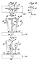
- FIGS 1-3 illustrate a manual knife sharpener 10 in accordance with one embodiment of this invention.
- the portion illustrated is directed to the relationship between the guide structure and the sharpening structure.
- Various other features such as a housing are not illustrated.
- each sharpening member has an abrasive surface 14,14.
- a knife 16 would be placed as shown in a space formed between the abrasive surface 14 and the linear guide surface 18 of a guide member 20.
- the angle A between the abrasive surface 16 and the linear guide surface 18 would determine the angle at which the blade facet 22 would be sharpened.
- Each sharpening member 12,12 may be disposed at the same or a different angle than the other member and/or may include different forms of abrasive surfaces to vary the sharpening action.
- the sharpening member can be shaped to have a circular, oval, rectangular or triangular cross section for example, and various faces or areas can be coated with different abrasive grit sizes so that alternate faces can be presented, if desired, to the blade facet when placed in contact with that member.
- a fixed support structure 24 is provided which fixedly mounts support post 26.
- Guide 20 is mounted to support post 26 by links 28,28 which are pivotally connected at one end by pivot pin 30 to support post 26 and pivotally connected at their opposite end by pin 32 to guide 20.
- Springs 34 mounted to support structure 24 and guide 20 tend to hold or bias the guide 20 in a central condition when no force is applied to the guide 20. Counterweights can be used instead of springs to serve the same function.
- the movement of guide 20 is solely a lateral movement without any pivoting or angular changes relative to the abrasive surface.
- the blade face 36 is always held in sliding contact against the guide surface 18 and its edge facet 22 is always presented to the plane of the abrasive surface 14 at the same angle.
- FIG 3 shows the guide 20 to be moved to the left with the restoring springs 34,34 also being moved.
- guide 20 moves in the same manner as illustrated in Figure 3, but in the opposite direction, namely toward the right. The facet of blade 16 opposite to that of facet 22 would then be sharpened in the same manner previously described.
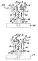
- FIGS 5-6 show a modified form of sharpener 10A.
- a pair of abrasive sharpening members 12,12 is provided, each of which has an abrasive surface 14.
- the blade 16 would be placed in the space formed between the abrasive surface 14 and a guide surface 38 on a guide member 40.
- two such guide members 40,40 are provided each with its linear guide surface 38.
- the two spaced guide members 40,40 are connected together by intersecting links 42,42 pivoted at a central location by pin 44.
- a T-shaped support post 46 is fixedly mounted to base or fixed support 24.
- Support post 46 includes a pair of elongated slots 48,48.
- each link 42,42 is provided with a pin or other member 50 to slide in a respective slot 48.
- the opposite end of each link 42,42 is provided with a pin or other member 52,52 to slide in an elongated slot 54 in a respective guide member 40.
- a pair of springs 56,56 connects the sets of links 42,42 together as illustrated in Figure 5 to hold the pins 52,52 in their lower most position in slots 54,54.
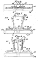
- FIGS 7-8 illustrate yet a further sharpener 10B in accordance with this invention.
- a stationary member or fixed slide rod 58 is mounted to fixed base 24 by having the ends 60 secured to the base 24 in any suitable manner.
- a sleeve in the form of a support block 61 is slidably mounted on fixed slide rod 58.
- a return spring 64,64 is located on each side of support block or slide bearing 61 to urge the support block into a centrally located position.
- Guide member 66 can be secured to support block 61 by any of a variety of means including adhesives or by means of a key 68 at the end of guide member 66. Key 68 is located in keyway 62.
- Support block 61 may slidably move on slide rod 58 without any rotational motion by any suitable interconnection such as a key/keyway or by slide rod 58 being of non-circular cross section and block 61 having a complementary shaped passage through which slide rod 58 extends. Because of the interconnection of guide member 66 to block 61, movement of guide member 66 carries block 61 with it.
- Figure 9 shows yet another sharpener 10C in accordance with this invention which is similar to the sharpener of Figures 7-8.
- the guide member 72 of Figure 9 is a generally T-shaped support fixedly mounted at its lower end to support block 61. Block 61 would be mounted to slide rod 58 in the same manner as described with respect to Figure 7.
- a shaft 74 is located at each side of guide member 72. Each shaft 74 is journaled at its upper end to guide member 72 and at its lower end into slide block 61 in any suitable manner. In the embodiment of Figure 9 each shaft 74 extends through a guide roller 76.
- the guide surface is actually the outer surface 78 of elongated roller 76.
- sharpener 10C would otherwise be similar to that of sharpener 10B in Figures 7-8. With the sharpener 10C of Figure 9 displacement of the entire guide member 72 would result when the blade 16 is moved into the space created by the abrasive surface 14 and the rolling outer surface 78 of rollers 76.
- the utilization of a sleeve bearing or slide block 61 on the slide rod 58 permits the guide member 72 of Figure 9 to be laterally displaced when the force from the blade 16 causes the sleeve bearing 61 to which guide member 72 is rigidly attached to move.
- the guide member 72 is thus displaced perpendicular to its guide surface and the excellent alignment of the sleeve bearing 61 on the slide rod 58 ensures that the guiding surface 78 is always parallel to its last and to any future position created by its perpendicular displacement.
- Springs 64 are used to restore the guide 72 to its neutral position whenever the knife 16 is removed. Springs are also used with the other embodiments shown herein to assist in maintaining parallel motion of the guide surfaces.
- Design of the surface of the linear guide surface is important to minimize scratching of that face of the blade which is held against the face of the linear guide surface while the edge facet 22 is moved in contact with the abrasive surface 14.
- Using a flocked coating or a polymer coating on the linear guide surface can minimize scratching.
- Rollers, such as rollers 76, can be used to form or constitute the linear guide surface. Such rollers will rotate as the knife face is moved linearly against their surface, thus minimizing or eliminating scratching of the face of the blade.
- the surface of the roller can, if desired, be plastic, rubberized or flocked to minimize scratching.
- Figure 9 shows such variation where linear rollers 76 mounted on the guide structure or guide member 72 serve as the guiding surface 78.
- the face 36 of the blade held in sliding contact with that surface 78 and the rolling action of the roller 76 reduces friction against the face 36 of the blade as the blade is moved forward between the guide surface 78 and the abrasive surface 14.
- a series of small rollers or balls can be used similarly as an alternative to a single roller.
- FIG. 10 and 11 Still another physical arrangement of a sharpener with a guide member 80 is shown in Figures 10 and 11.
- This guide member 80 with parallel guide surfaces 36 is supported by three rollers 83 that are attached to and move with the guide member 80.
- the rollers 83 ride along support structure 81, one roller above central support structure 81 and two below structure lateral extensions 82 attached to base 24.
- the triangular configuration of the rollers insures that the guide member can move only in a direction perpendicular to the guide surfaces 36.
- the circumference of the roller 83 can be grooved in order to retain the rollers securely on support structure 81,82.
- Blade 16 is inserted between guide surface 36 and the abrasive surface 14 with the face of the blade parallel to and in contact with the guide surface 36.
- the guide member 80 will shift to the left. Conversely when inserted and moved along the opposite guide surface 36 the guide member 80 will move to the right. Springs 84 attached to guide member 80 and support extensions 82 will act to restore the guide member to a centered position when the blade is removed. Stops 85 on support structure 81 can be used to limit travel of the guide member to that distance between such stops.
- a magnetic material or structure can be aligned with the guide surface to provide an appropriate magnetic attraction of the face of the blade to the guide surface thereby assisting the operator maintain good contact of the blade face with the guide surface.
- the magnitude of the magnetic attraction should not be so large as to impede ready movement of the blade face along the guide surface.
Landscapes
- Engineering & Computer Science (AREA)
- Mechanical Engineering (AREA)
- Finish Polishing, Edge Sharpening, And Grinding By Specific Grinding Devices (AREA)
Applications Claiming Priority (2)
| Application Number | Priority Date | Filing Date | Title |
|---|---|---|---|
| US26098001P | 2001-01-11 | 2001-01-11 | |
| US260980P | 2001-01-11 |
Publications (3)
| Publication Number | Publication Date |
|---|---|
| EP1223006A2 true EP1223006A2 (fr) | 2002-07-17 |
| EP1223006A3 EP1223006A3 (fr) | 2004-01-21 |
| EP1223006B1 EP1223006B1 (fr) | 2006-05-10 |
Family
ID=22991467
Family Applications (1)
| Application Number | Title | Priority Date | Filing Date |
|---|---|---|---|
| EP02000693A Expired - Lifetime EP1223006B1 (fr) | 2001-01-11 | 2002-01-11 | Affûteur manuel à couteaux avec dispositif de contrôle d'angle |
Country Status (9)
| Country | Link |
|---|---|
| US (1) | US6726551B2 (fr) |
| EP (1) | EP1223006B1 (fr) |
| JP (1) | JP2002224937A (fr) |
| CN (1) | CN1209226C (fr) |
| AU (1) | AU783401B2 (fr) |
| BR (1) | BR0202245A (fr) |
| CA (1) | CA2367189A1 (fr) |
| DE (1) | DE60211226D1 (fr) |
| HK (1) | HK1049462B (fr) |
Cited By (3)
| Publication number | Priority date | Publication date | Assignee | Title |
|---|---|---|---|---|
| US6595837B2 (en) * | 2000-04-10 | 2003-07-22 | Whirlpool Corporation | Sharpening stand for a cutlery device |
| EP3415271A1 (fr) * | 2017-06-12 | 2018-12-19 | Josef Luber | Dispositif aiguiseur de couteaux |
| WO2019120600A1 (fr) * | 2017-12-18 | 2019-06-27 | Zwilling J.A. Henckels Ag | Dispositif d'affûtage de couteau |
Families Citing this family (40)
| Publication number | Priority date | Publication date | Assignee | Title |
|---|---|---|---|---|
| US6875093B2 (en) * | 2002-10-15 | 2005-04-05 | Edgecraft Corporation | Sharpening device |
| US7287445B2 (en) * | 2003-03-27 | 2007-10-30 | Edgecraft Corporation | Apparatus for precision steeling/conditioning of knife edges |
| US7517275B2 (en) * | 2003-03-27 | 2009-04-14 | Edgecraft Corp. | Apparatus for precision steeling/conditioning of knife edges |
| US8430720B2 (en) * | 2003-03-27 | 2013-04-30 | Edgecraft Corporation | Apparatus for precision steeling/conditioning of knife edges |
| CN1771109B (zh) * | 2003-03-27 | 2011-09-21 | 埃奇克拉夫特公司 | 用于沿切削刃进行刃磨并且制作微刀片的精密装置 |
| EP1624995B1 (fr) * | 2003-04-17 | 2012-02-15 | Lee Valley Tools Ltd. | Ensemble formant guide de pierrage |
| DE112004001505B4 (de) * | 2003-08-13 | 2018-02-08 | Edgecraft Corp. | Manuelle Schärfvorrichtung |
| USD513955S1 (en) * | 2003-10-10 | 2006-01-31 | Edgecraft Corporation | Manual knife sharpener |
| US20060040598A1 (en) * | 2004-08-20 | 2006-02-23 | Rudolf Koppe | Precision sharpener tool |
| US7467991B2 (en) * | 2004-10-22 | 2008-12-23 | Gb Ii Corporation | Knife sharpener |
| GB2443596B (en) * | 2005-09-30 | 2010-02-17 | Edgecraft Corp | Precision control of sharpening angles |
| WO2007101008A2 (fr) * | 2006-02-23 | 2007-09-07 | Edgecraft Corporation | Affuteurs de couteaux munis de guide-couteaux ameliores |
| US7413504B2 (en) * | 2006-10-20 | 2008-08-19 | Michael Lytinas | Blade sharpening device with blade contour copying device |
| WO2008130900A1 (fr) * | 2007-04-18 | 2008-10-30 | Edgecraft Corporation | Affûteuse de précision pour couteaux de chasse et couteaux asiatiques |
| USD575124S1 (en) * | 2008-03-15 | 2008-08-19 | Smith Abrasives Inc. | Electric sharpener |
| DE202009014935U1 (de) * | 2009-03-04 | 2010-09-23 | Friedr. Dick Gmbh & Co. Kg | Schärfvorrichtung für Messerklingen |
| US20100304646A1 (en) * | 2009-05-15 | 2010-12-02 | Michael Lytinas | Blade sharpening device |
| JP5629773B2 (ja) * | 2009-08-07 | 2014-11-26 | エッジクラフト コーポレイション | クロス状に研削されたエッジを作成するための新規な研ぎ器 |
| CN102079058B (zh) * | 2010-12-01 | 2012-11-21 | 清华大学 | 钢板表面磁吸附升降式磨削装置 |
| CN102642165B (zh) * | 2011-02-18 | 2016-05-11 | 杭州泰科实业有限公司 | 地漏保温板的磨削装置及其磨削方法 |
| USD675502S1 (en) | 2011-10-03 | 2013-02-05 | Richard Carleton | Knife sharpening kit |
| US20130267153A1 (en) * | 2012-04-06 | 2013-10-10 | Hans-Peter Zahnd | Grinding machine |
| US9289874B1 (en) * | 2012-05-03 | 2016-03-22 | Daniel B. Sabo | Modular honing guide system |
| US10744614B1 (en) | 2013-05-08 | 2020-08-18 | Clay A. Allison | Adjustable sharpening apparatus and method for cutting implements |
| US11052512B1 (en) | 2013-05-08 | 2021-07-06 | Clay A. Allison | Adjustable knife sharpener and clamping assembly |
| US9216488B2 (en) * | 2013-05-08 | 2015-12-22 | Clay A. Allison | Adjustable sharpening apparatus and method for cutting implements |
| US9469014B2 (en) * | 2013-11-26 | 2016-10-18 | Wolff Industries, Inc. | Conditioning device for conditioning a blade |
| CN105710792A (zh) * | 2016-01-25 | 2016-06-29 | 田新明 | 一种快速磨刀石 |
| CN108568709A (zh) * | 2017-03-09 | 2018-09-25 | 林国平 | 蛤刃刀磨制方法 |
| CN110052977A (zh) * | 2018-01-19 | 2019-07-26 | 尹金树 | 手磨磨刀具 |
| US10850361B1 (en) | 2019-05-29 | 2020-12-01 | Darex, Llc | Powered sharpener with manual hone stage |
| CN110815072B (zh) * | 2019-11-12 | 2021-09-14 | 深圳市黄金庄园科技有限公司 | 一种磨刀口可移动的磨刀器 |
| US11565375B2 (en) | 2019-12-18 | 2023-01-31 | Aob Products Company | Sharpening device |
| CN113021187B (zh) * | 2021-02-26 | 2022-05-03 | 浙江大学山东工业技术研究院 | 一种刀片自动化打磨机构 |
| US11376713B1 (en) | 2021-03-09 | 2022-07-05 | Sharkninja Operating Llc | Knife sharpening systems |
| US11897076B2 (en) | 2021-04-20 | 2024-02-13 | Clay A. Allison | Knife sharpener with clamping assembly |
| USD997675S1 (en) | 2021-10-06 | 2023-09-05 | Darex, Llc | Power sharpener |
| US12350783B2 (en) | 2022-06-10 | 2025-07-08 | Clay A. Allison | Clamping assembly for a blade sharpener |
| CN115194565B (zh) * | 2022-07-21 | 2024-01-26 | 余姚市诺顿电器有限公司 | 一种磨刀器 |
| CN116175288B (zh) * | 2023-04-27 | 2023-08-25 | 中国机械总院集团宁波智能机床研究院有限公司 | 一种可转位刀片自动定位装置 |
Family Cites Families (9)
| Publication number | Priority date | Publication date | Assignee | Title |
|---|---|---|---|---|
| GB1343025A (en) * | 1970-10-13 | 1974-01-10 | Parr W G | Sharpening of blades |
| US4897965A (en) * | 1984-03-12 | 1990-02-06 | Friel Daniel D | Knife sharpening apparatus |
| US5404679A (en) * | 1984-03-12 | 1995-04-11 | Edgecraft Corporation | Portable manual sharpener for knives and the like |
| US4627194A (en) * | 1984-03-12 | 1986-12-09 | Friel Daniel D | Method and apparatus for knife and blade sharpening |
| US5390431A (en) * | 1992-06-18 | 1995-02-21 | Edgecraft Corporation | Method and apparatus for knife and blade sharpening |
| US5582535A (en) * | 1992-06-18 | 1996-12-10 | Edgecraft Corporation | Method and apparatus for knife and blade sharpening |
| US5478272A (en) * | 1994-07-07 | 1995-12-26 | Cozzini, Inc. | Blade sharpening apparatus |
| US5620359A (en) * | 1994-10-07 | 1997-04-15 | Cuisine De France, Ltd. | Knife sharpener |
| US6113476A (en) * | 1998-01-08 | 2000-09-05 | Edgecraft Corp. | Versatile ultrahone sharpener |
-
2001
- 2001-12-18 US US10/023,190 patent/US6726551B2/en not_active Expired - Lifetime
-
2002
- 2002-01-08 JP JP2002001444A patent/JP2002224937A/ja active Pending
- 2002-01-08 AU AU10083/02A patent/AU783401B2/en not_active Ceased
- 2002-01-10 BR BR0202245-1A patent/BR0202245A/pt not_active IP Right Cessation
- 2002-01-10 CA CA002367189A patent/CA2367189A1/fr not_active Abandoned
- 2002-01-11 EP EP02000693A patent/EP1223006B1/fr not_active Expired - Lifetime
- 2002-01-11 CN CNB021009953A patent/CN1209226C/zh not_active Expired - Fee Related
- 2002-01-11 DE DE60211226T patent/DE60211226D1/de not_active Expired - Lifetime
-
2003
- 2003-03-04 HK HK03101579.4A patent/HK1049462B/zh not_active IP Right Cessation
Cited By (4)
| Publication number | Priority date | Publication date | Assignee | Title |
|---|---|---|---|---|
| US6595837B2 (en) * | 2000-04-10 | 2003-07-22 | Whirlpool Corporation | Sharpening stand for a cutlery device |
| EP3415271A1 (fr) * | 2017-06-12 | 2018-12-19 | Josef Luber | Dispositif aiguiseur de couteaux |
| WO2019120600A1 (fr) * | 2017-12-18 | 2019-06-27 | Zwilling J.A. Henckels Ag | Dispositif d'affûtage de couteau |
| US11229988B2 (en) | 2017-12-18 | 2022-01-25 | Zwilling J.A. Henckels Ag | Knife sharpening device |
Also Published As
| Publication number | Publication date |
|---|---|
| EP1223006A3 (fr) | 2004-01-21 |
| CN1209226C (zh) | 2005-07-06 |
| HK1049462B (zh) | 2006-02-24 |
| AU783401B2 (en) | 2005-10-20 |
| BR0202245A (pt) | 2002-10-01 |
| HK1049462A1 (en) | 2003-05-16 |
| AU1008302A (en) | 2002-07-18 |
| JP2002224937A (ja) | 2002-08-13 |
| CN1367065A (zh) | 2002-09-04 |
| CA2367189A1 (fr) | 2002-07-11 |
| US6726551B2 (en) | 2004-04-27 |
| US20020094768A1 (en) | 2002-07-18 |
| DE60211226D1 (de) | 2006-06-14 |
| EP1223006B1 (fr) | 2006-05-10 |
Similar Documents
| Publication | Publication Date | Title |
|---|---|---|
| US6726551B2 (en) | Manual knife sharpener with angle control | |
| US6881137B2 (en) | Manual knife sharpener with angle control | |
| US11685010B2 (en) | Adjustable sharpening apparatus and method for cutting implements | |
| US5449315A (en) | Portable manual sharpener for knives and the like | |
| US11498186B2 (en) | Sharpener with precise adjustment capabilities | |
| US8092279B2 (en) | Sharpening system for scissors with complex curved blades | |
| US10131028B1 (en) | Adjustable sharpening apparatus and method for cutting implements | |
| US9216488B2 (en) | Adjustable sharpening apparatus and method for cutting implements | |
| CA2309222C (fr) | Affuteuse de patins | |
| US3883995A (en) | Automatic sharpening device | |
| US11975420B2 (en) | Sharpener with swing arm abrasive assembly | |
| US5295328A (en) | Device for the sharpening, grinding and polishing of dental, parodental and/or surgical instruments | |
| WO1996033046A1 (fr) | Mecanisme d'affutage de patins | |
| US7335093B1 (en) | Blade sharpening holder | |
| US20060040600A1 (en) | Precision sharpener tool | |
| CN208697198U (zh) | 一种磨刀器 | |
| US20240367291A1 (en) | Tool sharpening system | |
| US20260048466A1 (en) | Sharpening tool | |
| US963117A (en) | Razor-strop. | |
| JPH09193028A (ja) | 刃物研ぎ器 | |
| CN221473361U (zh) | 一种特种钢筋加工用定距切割装置 | |
| CN118636068A (zh) | 一种磨刀装置及磨刀方法 | |
| US1170116A (en) | Machine for sharpening and similar operations. | |
| JP3136095U (ja) | 刃物の研ぎ具 | |
| WO2023048700A1 (fr) | Aiguiseur comprenant ensemble abrasif à bras oscillant |
Legal Events
| Date | Code | Title | Description |
|---|---|---|---|
| PUAI | Public reference made under article 153(3) epc to a published international application that has entered the european phase |
Free format text: ORIGINAL CODE: 0009012 |
|
| AK | Designated contracting states |
Kind code of ref document: A2 Designated state(s): AT BE CH CY DE DK ES FI FR GB GR IE IT LI LU MC NL PT SE TR |
|
| AX | Request for extension of the european patent |
Free format text: AL;LT;LV;MK;RO;SI |
|
| RIN1 | Information on inventor provided before grant (corrected) |
Inventor name: FRIEL, DANIEL D. C/O EDGECRAFT CORPORATION |
|
| PUAL | Search report despatched |
Free format text: ORIGINAL CODE: 0009013 |
|
| AK | Designated contracting states |
Kind code of ref document: A3 Designated state(s): AT BE CH CY DE DK ES FI FR GB GR IE IT LI LU MC NL PT SE TR |
|
| AX | Request for extension of the european patent |
Extension state: AL LT LV MK RO SI |
|
| RIC1 | Information provided on ipc code assigned before grant |
Ipc: 7B 24D 15/08 A Ipc: 7B 24D 15/06 B Ipc: 7B 24B 3/54 B |
|
| 17P | Request for examination filed |
Effective date: 20040721 |
|
| AKX | Designation fees paid |
Designated state(s): DE FR GB SE |
|
| 17Q | First examination report despatched |
Effective date: 20041118 |
|
| GRAP | Despatch of communication of intention to grant a patent |
Free format text: ORIGINAL CODE: EPIDOSNIGR1 |
|
| GRAS | Grant fee paid |
Free format text: ORIGINAL CODE: EPIDOSNIGR3 |
|
| GRAA | (expected) grant |
Free format text: ORIGINAL CODE: 0009210 |
|
| AK | Designated contracting states |
Kind code of ref document: B1 Designated state(s): DE FR GB SE |
|
| REG | Reference to a national code |
Ref country code: GB Ref legal event code: FG4D |
|
| REF | Corresponds to: |
Ref document number: 60211226 Country of ref document: DE Date of ref document: 20060614 Kind code of ref document: P |
|
| PG25 | Lapsed in a contracting state [announced via postgrant information from national office to epo] |
Ref country code: SE Free format text: LAPSE BECAUSE OF FAILURE TO SUBMIT A TRANSLATION OF THE DESCRIPTION OR TO PAY THE FEE WITHIN THE PRESCRIBED TIME-LIMIT Effective date: 20060810 |
|
| PG25 | Lapsed in a contracting state [announced via postgrant information from national office to epo] |
Ref country code: DE Free format text: LAPSE BECAUSE OF FAILURE TO SUBMIT A TRANSLATION OF THE DESCRIPTION OR TO PAY THE FEE WITHIN THE PRESCRIBED TIME-LIMIT Effective date: 20060811 |
|
| ET | Fr: translation filed | ||
| PLBE | No opposition filed within time limit |
Free format text: ORIGINAL CODE: 0009261 |
|
| STAA | Information on the status of an ep patent application or granted ep patent |
Free format text: STATUS: NO OPPOSITION FILED WITHIN TIME LIMIT |
|
| 26N | No opposition filed |
Effective date: 20070213 |
|
| GBPC | Gb: european patent ceased through non-payment of renewal fee |
Effective date: 20070111 |
|
| REG | Reference to a national code |
Ref country code: FR Ref legal event code: ST Effective date: 20070930 |
|
| PG25 | Lapsed in a contracting state [announced via postgrant information from national office to epo] |
Ref country code: GB Free format text: LAPSE BECAUSE OF NON-PAYMENT OF DUE FEES Effective date: 20070111 |
|
| PG25 | Lapsed in a contracting state [announced via postgrant information from national office to epo] |
Ref country code: FR Free format text: LAPSE BECAUSE OF NON-PAYMENT OF DUE FEES Effective date: 20070131 |