EP1223057A2 - Transponder, Abfragegeräte und System damit - Google Patents
Transponder, Abfragegeräte und System damit Download PDFInfo
- Publication number
- EP1223057A2 EP1223057A2 EP02000199A EP02000199A EP1223057A2 EP 1223057 A2 EP1223057 A2 EP 1223057A2 EP 02000199 A EP02000199 A EP 02000199A EP 02000199 A EP02000199 A EP 02000199A EP 1223057 A2 EP1223057 A2 EP 1223057A2
- Authority
- EP
- European Patent Office
- Prior art keywords
- transponder
- frequency
- energy
- signal
- electromagnetic wave
- Prior art date
- Legal status (The legal status is an assumption and is not a legal conclusion. Google has not performed a legal analysis and makes no representation as to the accuracy of the status listed.)
- Granted
Links
- 239000003990 capacitor Substances 0.000 claims abstract description 56
- 238000012545 processing Methods 0.000 claims description 21
- 238000001514 detection method Methods 0.000 claims description 18
- 230000005540 biological transmission Effects 0.000 claims description 9
- 230000008054 signal transmission Effects 0.000 claims description 4
- 238000004891 communication Methods 0.000 abstract description 14
- 238000006243 chemical reaction Methods 0.000 description 15
- 239000000758 substrate Substances 0.000 description 12
- 238000012546 transfer Methods 0.000 description 9
- 238000010586 diagram Methods 0.000 description 8
- 238000000034 method Methods 0.000 description 6
- 230000010355 oscillation Effects 0.000 description 5
- 238000009434 installation Methods 0.000 description 4
- 239000011347 resin Substances 0.000 description 4
- 229920005989 resin Polymers 0.000 description 4
- 230000005674 electromagnetic induction Effects 0.000 description 3
- 230000006870 function Effects 0.000 description 3
- 230000002411 adverse Effects 0.000 description 2
- 239000011324 bead Substances 0.000 description 2
- 230000008878 coupling Effects 0.000 description 2
- 238000010168 coupling process Methods 0.000 description 2
- 238000005859 coupling reaction Methods 0.000 description 2
- 230000005672 electromagnetic field Effects 0.000 description 2
- 230000002093 peripheral effect Effects 0.000 description 2
- 230000008569 process Effects 0.000 description 2
- 239000004065 semiconductor Substances 0.000 description 2
- 230000004075 alteration Effects 0.000 description 1
- 238000007689 inspection Methods 0.000 description 1
- 238000012986 modification Methods 0.000 description 1
- 230000004048 modification Effects 0.000 description 1
- 238000000465 moulding Methods 0.000 description 1
Images


Classifications
-
- H—ELECTRICITY
- H01—ELECTRIC ELEMENTS
- H01Q—ANTENNAS, i.e. RADIO AERIALS
- H01Q1/00—Details of, or arrangements associated with, antennas
- H01Q1/12—Supports; Mounting means
- H01Q1/22—Supports; Mounting means by structural association with other equipment or articles
- H01Q1/2208—Supports; Mounting means by structural association with other equipment or articles associated with components used in interrogation type services, i.e. in systems for information exchange between an interrogator/reader and a tag/transponder, e.g. in Radio Frequency Identification [RFID] systems
- H01Q1/2241—Supports; Mounting means by structural association with other equipment or articles associated with components used in interrogation type services, i.e. in systems for information exchange between an interrogator/reader and a tag/transponder, e.g. in Radio Frequency Identification [RFID] systems used in or for vehicle tyres
-
- B—PERFORMING OPERATIONS; TRANSPORTING
- B60—VEHICLES IN GENERAL
- B60C—VEHICLE TYRES; TYRE INFLATION; TYRE CHANGING; CONNECTING VALVES TO INFLATABLE ELASTIC BODIES IN GENERAL; DEVICES OR ARRANGEMENTS RELATED TO TYRES
- B60C23/00—Devices for measuring, signalling, controlling, or distributing tyre pressure or temperature, specially adapted for mounting on vehicles; Arrangement of tyre inflating devices on vehicles, e.g. of pumps or of tanks; Tyre cooling arrangements
- B60C23/02—Signalling devices actuated by tyre pressure
- B60C23/04—Signalling devices actuated by tyre pressure mounted on the wheel or tyre
- B60C23/0408—Signalling devices actuated by tyre pressure mounted on the wheel or tyre transmitting the signals by non-mechanical means from the wheel or tyre to a vehicle body mounted receiver
- B60C23/041—Means for supplying power to the signal- transmitting means on the wheel
- B60C23/0413—Wireless charging of active radio frequency circuits
-
- B—PERFORMING OPERATIONS; TRANSPORTING
- B60—VEHICLES IN GENERAL
- B60C—VEHICLE TYRES; TYRE INFLATION; TYRE CHANGING; CONNECTING VALVES TO INFLATABLE ELASTIC BODIES IN GENERAL; DEVICES OR ARRANGEMENTS RELATED TO TYRES
- B60C23/00—Devices for measuring, signalling, controlling, or distributing tyre pressure or temperature, specially adapted for mounting on vehicles; Arrangement of tyre inflating devices on vehicles, e.g. of pumps or of tanks; Tyre cooling arrangements
- B60C23/02—Signalling devices actuated by tyre pressure
- B60C23/04—Signalling devices actuated by tyre pressure mounted on the wheel or tyre
- B60C23/0408—Signalling devices actuated by tyre pressure mounted on the wheel or tyre transmitting the signals by non-mechanical means from the wheel or tyre to a vehicle body mounted receiver
- B60C23/0422—Signalling devices actuated by tyre pressure mounted on the wheel or tyre transmitting the signals by non-mechanical means from the wheel or tyre to a vehicle body mounted receiver characterised by the type of signal transmission means
- B60C23/0433—Radio signals
-
- B—PERFORMING OPERATIONS; TRANSPORTING
- B60—VEHICLES IN GENERAL
- B60C—VEHICLE TYRES; TYRE INFLATION; TYRE CHANGING; CONNECTING VALVES TO INFLATABLE ELASTIC BODIES IN GENERAL; DEVICES OR ARRANGEMENTS RELATED TO TYRES
- B60C23/00—Devices for measuring, signalling, controlling, or distributing tyre pressure or temperature, specially adapted for mounting on vehicles; Arrangement of tyre inflating devices on vehicles, e.g. of pumps or of tanks; Tyre cooling arrangements
- B60C23/02—Signalling devices actuated by tyre pressure
- B60C23/04—Signalling devices actuated by tyre pressure mounted on the wheel or tyre
- B60C23/0408—Signalling devices actuated by tyre pressure mounted on the wheel or tyre transmitting the signals by non-mechanical means from the wheel or tyre to a vehicle body mounted receiver
- B60C23/0479—Communicating with external units being not part of the vehicle, e.g. tools for diagnostic, mobile phones, electronic keys or service stations
-
- B—PERFORMING OPERATIONS; TRANSPORTING
- B60—VEHICLES IN GENERAL
- B60C—VEHICLE TYRES; TYRE INFLATION; TYRE CHANGING; CONNECTING VALVES TO INFLATABLE ELASTIC BODIES IN GENERAL; DEVICES OR ARRANGEMENTS RELATED TO TYRES
- B60C23/00—Devices for measuring, signalling, controlling, or distributing tyre pressure or temperature, specially adapted for mounting on vehicles; Arrangement of tyre inflating devices on vehicles, e.g. of pumps or of tanks; Tyre cooling arrangements
- B60C23/02—Signalling devices actuated by tyre pressure
- B60C23/04—Signalling devices actuated by tyre pressure mounted on the wheel or tyre
- B60C23/0491—Constructional details of means for attaching the control device
- B60C23/0493—Constructional details of means for attaching the control device for attachment on the tyre
-
- Y—GENERAL TAGGING OF NEW TECHNOLOGICAL DEVELOPMENTS; GENERAL TAGGING OF CROSS-SECTIONAL TECHNOLOGIES SPANNING OVER SEVERAL SECTIONS OF THE IPC; TECHNICAL SUBJECTS COVERED BY FORMER USPC CROSS-REFERENCE ART COLLECTIONS [XRACs] AND DIGESTS
- Y10—TECHNICAL SUBJECTS COVERED BY FORMER USPC
- Y10T—TECHNICAL SUBJECTS COVERED BY FORMER US CLASSIFICATION
- Y10T152/00—Resilient tires and wheels
- Y10T152/10—Tires, resilient
- Y10T152/10027—Tires, resilient with wear indicating feature
Definitions
- the present invention relates to a transponder and a system thereof, and more particularly to charging a secondary battery and a capacitor such as a large scale capacitor which is used as a power source.
- the transponder is composed of an integrated circuit and an outer shell for protecting the integrated circuit, and has various shapes such as a small coin shape or a cylindrical column shape.
- an embedded position of the tansponder in a tire is set to the central portion at the tip end level of a carcass ply wound-up portion or on the outer surface of the carcass ply of the pad-less portion.
- a pneumatic tire with a transponder fitted in Japanese Utility Model Laid-Open No. 7-13505 specification there has been obtained by improving the above described technique.
- this pneumatic tire there is provided a transponder housing pocket in a protrusion provided on the inner peripheral surface of a bead portion of a troidal-shaped tire. More specifically, the protrusion having the transponder housing pocket is provided on the bead portion having few movement during traveling on the inner peripheral surface of the tire, which is off a portion constituting the tire. For this reason, the tire will not be adversely affected. Further since the transponder is capable of freely entering and going out of the pocket, it is possible to freely inspect the transponder housed or replace in case of necessity.
- the present invention has been achieved in views of the above described problems, and is aimed to provide a transponder, an interrogator and a system thereof in which a secondary battery and a capacitor such as a large scale capacitor are capable of being easily charged from the outside. It is another object of the present invention to provide a transponder, an interrogator and a system thereof in which charging can be easily performed from the outside and electric power consumption of the capacitor is restrained.
- a transponder system has a transponder and an interrogator, and has energy supplying means for radiating an electromagnetic wave of a second frequency from an antenna.
- This antenna is provided in at least one of a station and a parking lot for the vehicle.
- the energy supplying means radiates an electromagnetic wave to the transponder only when a vehicle equipped with the transponder is at a station or a parking lot for the vehicle. For this reason, when a vehicle equipped with a tire with a transponder is in a station or a parking lot for the vehicle, the transponder system according to the present invention radiates an electromagnetic wave of a second frequency from an antenna by means of the energy supplying means to thereby charge the capacitor for the transponder.
- the transponder receives a question signal from the interrogator through the use of the first frequency to convert electromagnetic wave energy of the signal of first frequency received into electric energy by means of first energy converting means.
- This electric energy operates a central processing unit and transmission means of the transponder.
- the central processing unit of the transponder reads storage information in the information storage means, and generates an electric signal for representing answering information to the question signal of the first frequency to output to the transmission means.
- the transmission means transmits the answering signal on the basis of the electric signal from the central processing unit.
- the transponder converts electromagnetic wave energy of the second frequency received by the second receiving means into electric energy by means of the second energy converting means.
- This electric energy charges the capacitor.
- Electric power accumulated in the capacitor is used as an auxiliary power source or a main power source for operating an additional circuit whose electric power consumption is larger than the main circuit.
- the capacitor can be charged by receiving the electromagnetic wave of the second frequency even when communication is performed with the interrogator, and the energy can be transmitted at higher efficiency than when the first frequency is used.
- a high frequency having fast data transfer speed can be used as the first frequency.
- the transponder according to the present invention has, as an additional circuit, a sensor portion for detecting predetermined physical quantity within the tire to output the detection result through an electric signal. Further, the central processing unit has means for taking in the detection result by the sensor portion to include into the answering information. For this reason, the transponder according to the present invention is capable of including physical quantity such as pneumatic pressure and temperature within the tire which has been detected by the sensor portion into the answering information to transmit. Further, the transponder according to the present invention has, in the sensor portion, at least one of a temperature sensor and a pneumatic pressure sensor. For this reason, the transponder according to the present invention is capable of transmitting answering information including information on the temperature and internal pressure of the tire which has been detected by the temperature sensor and the pneumatic pressure sensor.
- the transponder according to the present invention uses electric energy charged in the capacitor only to drive the sensor portion. Further, the transponder according to the present invention carries current to the sensor portion from the capacitor only for predetermined time until the physical quantity is detected by the sensor portion and the detection result is taken in the central processing unit. For this reason, the electric energy accumulated in the capacitor is consumed only in a necessary and minimal amount.
- the capacitor is constituted by a secondary battery or a large scale capacitor. Further, the capacitor has charging capacity capable of charging electrical energy sufficient to obtain detection result by the sensor portion at least once.
- the transponder has means for detecting whether or not it is necessary to charge the capacitor, and means for including a signal for requesting charging in an answering signal for transmitting when charging is required on the basis of this detection result. For this reason, for example, when an interrogator or a charging device receives the answering signal including the signal for requesting charging or the signal for requesting charging, the electromagnetic wave of the second frequency is radiated from the interrogator or the charging device to the transponder to automatically perform charging.
- the transponder according to the present invention has a loop coil-shaped antenna as an antenna for receiving electromagnetic wave of the second frequency.
- an antenna for transmitting electromagnetic wave of the second frequency is a similar loop coil-shaped antenna, and when these two antennas are approached to each other such that their coil axes substantially coincide with each other, electromagnetic induction by the Lenz's law is performed, and the energy can be transferred more effectively.
- the interrogator according to the present invention transmits a question signal to the transponder through the use of an electromagnetic wave of the first frequency by question signal transmission means, and receives an answering signal from the transponder to this question signal by means of receiving means. Further, the interrogator according to the present invention transmits, by means of the energy supplying means, an electromagnetic wave of the second frequency that is different from the first frequency to transfer the energy to the transponder through the electromagnetic wave of this second frequency.
- the interrogator Only when a signal for requesting supply of energy through electromagnetic wave of the second frequency is included in the answering signal, the interrogator according to the present invention has driving control means for driving the energy supplying means. For this reason, only when an answering signal including a signal for requesting charging is received, the energy supplying means is driven to radiate the electromagnetic wave of the second frequency to the transponder.
- an antenna for transmitting the electromagnetic wave of the second frequency to the transponder from the interrogator a coil-shaped or a volute loop antenna is used.
- an antenna for receiving the electromagnetic wave of the second frequency of the transponder is a similar loop antenna, and when these two antennas are approached to each other such that their coil axes substantially coincide with each other, electromagnetic induction by the Lenz's law is performed, and the energy can be transferred more effectively.
- the interrogator has means for detecting existence of the transponder within an area in which energy can be supplied, and driving control means for driving the energy supplying means when there exists the transponder within the area on the basis of this detection result. For this reason, when the existence of the transponder within the area in which the energy can be supplied is detected by means of the interrogator, the energy supplying means is driven and the electromagnetic wave of the second frequency is automatically transmitted from the interrogator to the transponder.
- size and shape of a casing in which each component of the interrogator has been housed are made into portable size and shape, whereby it has been made possible to easily carry it.
- the first frequency is set to a frequency above a short wave region to thereby improve the data transfer efficiency
- the second frequency is set to a frequency below a medium wave region to thereby improve the energy transfer efficiency.
- the second frequency is set to a frequency below 200 kHz to thereby further improve the energy transfer efficiency.
- the first frequency has been set to a frequency different from frequencies equal to the integer multiple of the second frequency.
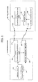
- FIG. 1 is a block diagram showing a configuration of a transponder system according to a first embodiment of the present invention.
- reference numeral 100 denotes a transponder.
- the transponder 100 is composed of: a data transmission-reception antenna (first reception means) 101; a charging antenna (second reception means) 102; a data transmission-reception unit (main circuit) 110; a sensor circuit (additional circuit) 130; and a sensor power circuit 150.
- Reference numeral 200 denotes an interrogator.
- the interrogator 200 is composed of: a data transmission-reception antenna 201; a charging antenna 202; a data transmission-reception unit 210; a sensor charging circuit 230; a display unit 250; and an operating unit 270.
- the sensor power circuit 150 supplies electric power to the sensor circuit 130. Further, when the electric power accumulated in the sensor circuit 130 becomes exhausted, the sensor circuit 130 is charged by the sensor charging circuit 230 of the interrogator 200 by wireless.
- the detail will be described.
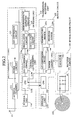
- FIG. 2 is a block diagram showing a detailed configuration of the transponder 100.
- a data transmission-reception unit 110 is composed of: an antenna changer 111; a power circuit (first energy conversion means) 112; an analog/digital (hereinafter, referred to as A/D) conversion circuit 113; a storage unit 114; a central processing unit 115; and an outgoing unit 116.
- A/D analog/digital
- the antenna changer 111 is composed of, for example, an electronic switch. This antenna changer 111 switches the data transmission-reception antenna 101 to either the power circuit 112 and the A/D conversion circuit 113 or the outgoing unit 116 in accordance with a control signal from the CPU 115a for connection.
- the antenna 101 is usually connected to the power circuit 112 through the antenna changer 111.
- the power circuit 112 is composed of a well-known full-wave rectifying circuit. On the input side of this power circuit 112, the antenna 101 is connected through the antenna changer 111. The power circuit 112 rectifies high-frequency current induced to the antenna 101 to convert into direct current, and outputs this direct current as a driving power source for other circuits such as the central processing unit 115, the storage unit 114 and the outgoing unit 116.
- the A/D conversion circuit 113 detects a question signal received, and thereafter, converts into digital data to output to the CPU115a.
- the central processing unit 115 is composed of an well-known CPU115a and a digital/analog (hereinafter, referred to as D/A) conversion circuit 115b.
- D/A digital/analog
- the CPU115a drives the sensor circuit 130 to take in detection result on temperature and pneumatic pressure.
- the central processing unit 115 generates answering information including the detection result taken in and identification information peculiar to itself, and transmits this information as an answering signal through the D/A conversion circuit 115b and the outgoing unit 116.
- the CPU115a regards the electric power accumulated in the sensor power circuit 150 as exhausted, and transmits an answering signal including a request for charging.
- the identification information has been stored within the storage unit 114 composed of an electrically rewritable non-volatile semiconductor memory such as EEPROM (Electrically Erasable Programmable Read-Only Memory).
- EEPROM Electrically Erasable Programmable Read-Only Memory
- This identification information is identification information peculiar to individual transponders 100, and has been stored in an area designated as read-only within the storage unit 114 in advance when the transponder 100 is manufactured.
- the outgoing unit 116 is composed of: a modulation circuit 116a; an oscillation circuit 116b; and a high-frequency amplifier circuit 116c.
- the outgoing unit 116 modulates a carrier wave obtained by oscillating through the use of the oscillation circuit 116b on the basis of the information signal inputted from the central processing unit 115 by the modulation circuit 116a, and supplies this to the antenna 101 through the high-frequency amplifier circuit 116c and the antenna changer 111.
- a frequency (first frequency) of a high-frequency signal to be outputted from the outgoing unit 116 a frequency of 13.56 MHz is used so as to obtain, for example, necessary and sufficient data transfer speed.
- the data transmission-reception antenna 101 has been set so as to produce resonance at a frequency of 13.56 MHz.
- the sensor circuit 130 is composed of: a storage unit 131; a CPU132; an A/D conversion circuit 133; a power control unit 134; a temperature sensor 135a; and a pneumatic pressure sensor 135b.
- Communication is performed between the CPU132 and the CPU115a of the transmission-reception unit 110. Also, on receipt of a request for temperature and pressure information from the CPU115a, the CPU132 acquires the temperature information and pressure information that the temperature sensor 135a and the pneumatic pressure sensor 135b have obtained by detecting through the A/D conversion circuit 133 to transmit these information to the CPU115a.
- a power control unit 134 is composed of, for example, an electronic switch, a booster type power circuit or the like, and the electronic switch is turned ON or OFF on the basis of a control signal that is received from the CPU115a of the data transmitter-receptor 110. Further, the power control unit 134 converts electric power to be outputted from the sensor power circuit 150 into voltage required to operate the circuit, and supplies to the storage unit 131, the CPU132, the A/D conversion circuit 133, the temperature sensor 135a and the pneumatic pressure sensor 135b.
- the sensor power circuit 150 is composed of a rectifier circuit (second energy converting means) 151 and a capacitor 152.
- the input side of the rectifier circuit 151 is connected to a charging antenna 102.
- the output side of the rectifier circuit 151 is connected to the capacitor 152, and also to the power control unit 134.
- the capacitor 152 is composed of, for example, a large scale capacitor or a secondary battery, and has a capacity sufficient to drive the sensor circuit 130 five times a day.
- the temperature sensor 135a and the pneumatic pressure sensor 135b the power consumption of which is 11 mA and the power supply voltage of which is 3 V
- the charging antenna 102 has been set so as to produce resonance at a frequency of 125 kHz.
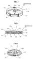
- FIG. 3 is an external perspective view showing the transponder 100
- FIG. 4 is its side sectional view
- FIG. 5 is a perspective view showing one surface of its circuit substrate
- FIG. 6 is a perspective view showing the other surface of the circuit substrate.
- the transponder 100 has been constituted by molding a disk-shaped multi-layer printed circuit substrate (hereinafter, referred to as circuit substrate simply) 301 which has been packaged with parts, through the use of resin 310. Also, a circular loop-shaped data transmission-reception antenna 101 and a charging antenna 102 have been embedded within the circuit substrate 301. Further, a capacitor 152 and a plurality of chip-shaped electronic parts 303 and IC chips 304 have been packaged on the surface 301a of the circuit substrate 301. Also, a cylindrical column chip-shaped temperature sensor 135a and a pneumatic pressure sensor 135b have been packaged on the back surface of the circuit substrate 301.
- the circuit substrate 301 which has been packaged with parts has been sealed with resin 310 with the exception of packaged portions of the temperature sensor 135a and the pneumatic pressure sensor 135b.
- This resin 310 is formed in a flat plate type cylindrical column shape.
- the packaged portions of the temperature sensor 135a and the pneumatic pressure sensor 135b have been formed with space so as to allow the open air to be taken in. This space communicates to the outside world through an aperture 311a of a protruded portion 311 provided on the resin 310.
- the above described transponder 100 is, like the tire with transponder 400 shown in FIG. 7, fitted to the inner side surface of the tire, and is fixed in such a manner that the surface of the circuit substrate 301 becomes substantially perpendicular and that the space within the tire communicates to the space in the packaged portions of the temperature sensor 135a and the pneumatic pressure sensor 135b through the aperture 311a.
- the tire with transponder 400 used in the present embodiment is a well-known tubeless radial tire, and a reference numeral 411 shown in the figure denotes a carcass; 412A, 412B, a belt; 413, an under tread; and 414, a cap tread.
- the transponder 100 is fitted to the tire in such a manner that the surface of the circuit substrate 301 becomes substantially perpendicular as described above, whereby the coil axis of a loop coil-shaped charging antenna 102 becomes substantially horizontal.
- the charging antenna 102 is capable of receiving a charging electromagnetic wave, and when an antenna 202 for radiating the charging electromagnetic wave is similarly loop coil-shaped; and is positioned close to the charging antenna 102, these antennas 102 and 202 can be easily electromagnetic-coupled to each other. This electromagnetic coupling enables energy to be transferred at higher efficiency than when energy is transferred with the electromagnetic wave as a medium.
- FIG. 8 is a block diagram showing a detailed configuration of an interrogator 200.
- a data transmission-reception unit 210 is composed of: an antenna changer 211; an A/D conversion circuit 213; a storage unit 214; a central processing unit 215; and an outgoing unit 216.
- the antenna changer 211 is composed of, for example, an electronic switch or the like. This antenna changer 211 switches the data transmission-reception antenna 201 to either the A/D conversion circuit 213 or the outgoing unit 216 in accordance with a control signal from the CPU 215a for connection.
- the antenna 201 is usually connected to the A/D conversion circuit 213 through the antenna changer 211.
- the A/D conversion circuit 213 detects a question signal received through the antenna 201, and thereafter, converts into digital data to output to the CPU115a.
- the storage unit 214 is composed of an electrically rewritable non-volatile semiconductor memory such as, for example, EEPROM (Electrically Erasable Programmable Read-Only Memory).
- EEPROM Electrically Erasable Programmable Read-Only Memory
- the central processing unit 215 is composed of the well-known CPU215a and a D/A conversion circuit 215b.
- the CPU215a operates on the basis of a preset program, and transmits a question signal to the transponder 100 in accordance with an instruction inputted through the operating unit 270, and receives an answering signal. Further, the CPU215a displays the answering information on the display unit 250, and causes the sensor charging circuit 230 to operate for charging the capacitor 152 for the transponder 100.
- the outgoing unit 216 is composed of: a modulation circuit 216a; an oscillation circuit 216b; and a high-frequency amplifier circuit 216c. Also, the outgoing unit 216 modulates a carrier wave obtained by oscillating through the use of the oscillation circuit 216b on the basis of the information signal inputted from the central processing unit 115 by the modulation circuit 216a, and supplies this to the antenna 201 through the high-frequency amplifier circuit 216c and the antenna changer 211.
- the frequency (first frequency) of a high-frequency signal to be outputted from the outgoing unit 216 a frequency of, for example, 13.56 MHz is used. For this reason, the data transmission-reception antenna 201 has been set so as to produce resonance at a frequency of 13.56 MHz.
- a sensor charging circuit 230 is composed of: a power unit 231; electronic switches 232, 233; and an oscillator 234.
- the input side of the power unit 231 is constructed so as to be able to connect to the commercial power source 281.
- the power unit 231 converts electric power supplied from the commercial power source 281 into voltage suitable for the input side of the oscillator 234 for output.
- the electronic switch 232 is an one-circuit and two-contact switch which is switched through a switching control signal from the operating unit 270, and connects either the power unit 231 or the large scale storage battery 282 to the input side of the oscillator 234.
- the electronic switch 233 is switched between ON and OFF through a switching control signal from the CPU215a to switch between supply and non-supply of electric power to the oscillator 234.
- the oscillator 234 generates sine wave voltage that alternates at a frequency of, for example, 125 kHz to output to the antenna 202.
- the frequency (second frequency) of sine wave voltage that is generated at the oscillator 234 it is preferable to use any frequency that the higher harmonic and the frequency for use with the data communication as described above do not coincide with. More specifically, when a charging electromagnetic wave is radiated from the charging antenna 202, a charging electromagnetic wave (alternating field) is generated in the vicinity of the transponder 100. For this reason, when the data communication frequency coincides with the higher harmonic, there exists a possibility where the data communication is disturbed. Accordingly, if the relationship between the data communication frequency and the charging frequency is set such that the data communication frequency does not coincide with the higher harmonic of the charging frequency, the data communication will be able to be favorably performed even when the charging electromagnetic wave is being radiated.
- any frequency below medium wave region is preferable, and further when electromagnetic coupling is taken into consideration, frequencies below 200 kHz are preferably used.
- the interrogator 200 is, as shown in, for example, FIG. 9, incorporated within a hand-held type housing 500 having a pistol shape. At the tip end portion of this housing 500, there are arranged a loop coil-shaped data transmission-reception antenna 201 and a charging antenna 202. On the top surface of the housing 500, there are arranged an operating unit 270 composed of a keyboard and a display unit 250, and at the bottom of a grip 501a, there is arranged a connector (not shown) for connecting the commercial power source 281 and an external storage battery 282.
- a driver or an inspection worker of a vehicle equipped with the tire with transponders 400 carries the interrogator 200 with him for working, whereby he is capable of reading data of temperature and pneumatic pressure of the tire from the transponder 100 and charging the capacitor 152 of the transponder 100.
- the antennas 201 and 202 of the interrogator 200 are directed toward the tire to input a transmission instruction of a question signal from the operating unit 270.
- the question signal is transmitted from the interrogator 200, an answering signal transmitted from the transponder 100 correspondingly thereto can be received, and the answering signal is displayed on the display unit 250.
- the capacity of the capacitor 152 of the transponder 100 is insufficient, a request for charging is transmitted from the transponder 100, and since the interrogator 200 drives a sensor charging circuit 230 correspondingly thereto, the capacitor 152 of the transponder 100 can be charged.
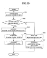
- the CPU115a of the transponder 100 starts driving by means of the energy of question signal electromagnetic wave received, electric power is supplied from the capacitor 152 to the sensor circuit 130 through the power control unit 134 (SA1). Thereafter, through communication with the CPU132 of the sensor circuit 130, the CPU115a judges whether or not the sensor circuit 130 has been driven (SA2). As the result of this judgment, when there is no answer from the CPU132, or when no normal answer can be obtained, the sequence will proceed to the processing at SA6 to be described later. Also, when a normal answer has been obtained from the CPU132, the CPU115a acquires detection information from the temperature sensor 135a and the pneumatic pressure sensor 135b (SA3).
- the CPU115a stops the supply of electric power from the capacitor 152 to the sensor circuit 130 through the power control unit 134 (SA4).
- the CPU115a generates an answering signal including temperature information and pneumatic pressure information acquired, and transmits this answering signal (SA5).
- the CPU115a judges the capacity of the capacitor 152 to be insufficient to sever the connection between the capacitor 152 and the sensor circuit 130 through the power control unit 134 (SA6). Further, the CPU115a generates an answering signal including a request for charging, and transmits this answering signal (SA7).
- the CPU215a of the interrogator 200 supervises whether or not a question signal transmission instruction has been inputted from the operating unit 270 (SB1), and on receipt of the question signal transmission instruction, transmits a question signal (SB2). Then, the CPU215a performs an answering signal receiving process (SB3) to judge whether or not the answering signal could be received (SB4).
- the CPU215a proceeds to the processing at the SB2 to transmit the question signal again. Also, when it could receive the answering signal, the CPU215a judges whether or not this answering signal includes the request for charging (SB5).
- the CPU215a displays the answering information including the temperature and pneumatic pressure information of the tire received on the display unit 250, and stores in the storage unit 214 (SB6). Also, when a request for charging is included in the answering signal, the CPU215a displays the answering information including the temperature and pneumatic pressure information of the tire received on the display unit 250 (SB7), and drives the sensor charging circuit 250 to radiate a charging electromagnetic wave (SB8).
- the CPU215a displays a message "Charging is in progress" on the display unit 250 (SB9), and after an electromagnetic wave is radiated for predetermined time, stops driving of the sensor charging circuit 230 (SB10) to proceed to the process at the SB1.
- the transponder 100 having the above described configuration, there is no need for replacing the internal battery unlike the conventional example even if a sensor circuit 130 having great electric power consumption is provided as an additional circuit.
- the transponder 100 can be semi-permanently used by charging the capacitor 152 for use.
- the capacitor 152 is charged through the use of an electromagnetic wave having a low frequency different from data communication, it is possible to charge the capacitor 152 at high efficiency. Further, at the time of charging the capacitor 152, the antenna 102 of the transponder 100 and the antenna 202 of the interrogator 200 can easily be electromagnetic-coupled. When they are electromagnetic-coupled as described above, the capacitor 152 can be charged at further higher efficiency.
- the transponder 100 supplies electric power to the sensor circuit 130 from the capacitor 152 only when necessary, the electric power consumption of the capacitor 152 can be restrained as far as possible.
- a transponder system has, in addition to the configuration according to the first embodiment, a charging device capable of easily charging the capacitor 152 for the transponder 100 in a vehicle parking lot or station.
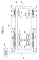
- FIG. 12 is a schematic plan view showing the structure for installing a charging device in a parking lot or a station
- FIG. 13 is a block diagram showing the configuration of the charging device
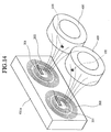
- FIG. 14 is a view for explaining an electromagnetic field state during charging.
- components identical to those in the above described first embodiment are designated by the identical reference numerals, and description thereof will be omitted.
- reference numeral 600 denotes a charging device; and 620, a parking and stopping area for a vehicle 700 in a parking lot or a station.
- antenna installation plates 611a to 611d composed of, for example, a concrete block or the like are provided so as to oppose to tires 400 of the vehicle 700.
- Each of the antenna installation plates 611a to 611d is, as shown in FIG. 14, provided with a loop coil-shaped data transmission-reception antenna 201 and a charging antenna 202 so as to oppose to the tire 400 of the vehicle 700 which has parked or stopped.
- These antennas 201 and 202 are arranged such that their coil axes become substantially horizontal and that the coil axis substantially coincides with the tire shaft.
- each antenna 201, 202 is connected to the charging device 600 through a coaxial cable 612 provided for each antenna.
- the charging device 600 is, as shown in FIG. 13, composed of: a data transmission-reception unit 210; a plurality of sensor charging circuits 240; an antenna changer 631; a CPU632; a storage unit 633; an operating unit 634; and a display unit 635, and has a function of the interrogator, a charging function and a transponder detection function.
- the antenna connection side of an antenna changer 211 in the data transmission-reception unit 210 is connected to the unit connection side of an antenna changer 631.
- the antenna changer 211 is adapted to be connected to any one of the data transmission-reception antennas 201 provided at each of the antenna installation plates 611a to 611d through the antenna changer 631.
- This antenna changer 631 is switched on the basis of a switching control signal from the CPU632.
- the CPU215a of the data transmission-reception unit 210 communicates with the CPU632, operates in accordance with the instruction from the CPU632, and transfers the information included in an answering signal received to the CPU632.
- Each sensor charging circuit 240 is constructed by excluding the electronic switch 232 from the sensor charging circuit 230, and the output side of the power unit 231 is connected to the oscillator 234 through the electronic switch 233.
- the electronic switch 233 performs an ON-OFF switching operation on the basis of a control signal from the CPU632.
- the output side of the oscillator 234 in each sensor charging circuit 240 is connected to respectively different charging antennas 202. More specifically, the output side of the oscillator 234 in each sensor charging circuit 240 is connected to any one of the charging antennas 202 provided at each of the antenna installation plates 611a to 611d.
- the CPU632 operates on the basis of the preset program. Further, when it has detected that the vehicle 700 is parking or stopping in the parking or stopping area 620, the CPU632 collects temperature and pneumatic pressure information for each tire 400, and drives each sensor charging circuit 240 to charge the capacitor 152 of the transponder 100.
- the CPU632 of the charging device 600 transmits a question signal through the data transmission-reception unit 210 (SC1), and judges whether or not an answering signal therefor could be received (SC2).
- SC1 data transmission-reception unit 210
- the CPU632 operates the antenna changer 631 to transmit a question signal to each antenna 201, and confirms the answering signal.
- the CPU632 counts predetermined timer time assuming that there is not present any vehicle equipped with a tire with transponder 400 within the parking and stopping area 620, and after the elapse of this timer time, proceeds to the processing at the SC1 to transmit the question signal again (SC3).
- the question signal is transmitted from the data transmission-reception unit 210 at predetermined timer time intervals and presence or absence of the answering signal from the transponder 100 is judged, whereby the existence of the transponder 100 within the parking and stopping area 620 can be easily detected.
- the CPU632 receives the answering signal (SC4), stores information included in the answering signal in the storage unit 633, and displays the information on the display unit 635(SC5).
- the CPU632 drives all the sensor charging circuits 240 to radiate a charging electromagnetic wave from the antenna 202 (SC6). Further, the CPU632 displays, on the display unit 635, a message representing that charging is under progress, for example, a message "Charging is under progress" (SC7). Thereafter, after a lapse of the charging time that has been preset in the program, the CPU632 stops the driving of all the sensor charging circuits 240 to complete the charging (SC8), and proceeds to the processing at the SC1.
- the CPU632 drives the sensor charging circuit 240 to radiate a charging electromagnetic wave from the antenna 202 as shown in FIG. 14, the charging antenna 202 and the charging antenna 102 within the transponder 100 are approached to each other such that their coil axes substantially coincide with each other, and therefore, these loop coil-shaped antennas 202 and 102 are electromagnetic-coupled. For this reason, between these antennas 202 and 102, electromagnetic induction by the Lenz's law is performed and energy is transferred efficiently. Therefore, the transfer energy loss to the transponder 100 is reduced, and charging can be performed at high efficiency.
- the electromagnetic wave energy of a frequency of 125 kHz (second frequency) received by the charging antenna 102 (second receiving means) enables the capacitor 152 to be charged, and therefore, by means of the electric power accumulated in this capacitor 152, the sensor circuit 130 (additional circuit), the electric power consumption of which is larger than the transmission-reception unit 110 (main circuit) can be operated. For this reason, such time and effort for battery replacement as in the conventional example can be omitted.
- the second frequency has been set to a lower frequency than the first frequency at which data communication is performed, it is possible to receive the electromagnetic wave of the second frequency for charging the capacitor 152 even when communication is being performed with the interrogator, and to transmit energy at higher efficiency than when the first frequency is used.
- the capacitor 152 of the transponder 100 can be charged very simply.
- the capacitor 152 of the transponder 100 can be charged very simply and automatically.
- each embodiment described above is one embodiment according to the present invention, and the present invention is not limited only to these.
- the charging device 600 the presence or absence of the transponder 100 has been detected through the use of the data transmission-reception unit of the interrogator 200, but if only a vehicle 700 equipped with the transponder 100 parks or stops in the parking and stopping area 620, the charging operation can be performed by detecting the presence or absence of the vehicle 700 in the parking and stopping area 620. Further, only when a request for charging has been received from the transponder 100 of the vehicle 700 which is parking or stopping in the parking and stopping area 620, the charging device 600 can be caused to perform the charging operation.
Landscapes
- Engineering & Computer Science (AREA)
- Mechanical Engineering (AREA)
- Computer Networks & Wireless Communication (AREA)
- Near-Field Transmission Systems (AREA)
- Arrangements For Transmission Of Measured Signals (AREA)
- Radar Systems Or Details Thereof (AREA)
- Tires In General (AREA)
- Charge And Discharge Circuits For Batteries Or The Like (AREA)
Applications Claiming Priority (2)
| Application Number | Priority Date | Filing Date | Title |
|---|---|---|---|
| JP2001003997 | 2001-01-11 | ||
| JP2001003997A JP4152595B2 (ja) | 2001-01-11 | 2001-01-11 | トランスポンダ及びそのシステム |
Publications (3)
| Publication Number | Publication Date |
|---|---|
| EP1223057A2 true EP1223057A2 (de) | 2002-07-17 |
| EP1223057A3 EP1223057A3 (de) | 2003-07-16 |
| EP1223057B1 EP1223057B1 (de) | 2009-07-08 |
Family
ID=18872247
Family Applications (1)
| Application Number | Title | Priority Date | Filing Date |
|---|---|---|---|
| EP02000199A Expired - Lifetime EP1223057B1 (de) | 2001-01-11 | 2002-01-10 | Transponder, Abfragegeräte und System damit |
Country Status (4)
| Country | Link |
|---|---|
| US (1) | US6791457B2 (de) |
| EP (1) | EP1223057B1 (de) |
| JP (1) | JP4152595B2 (de) |
| DE (1) | DE60232832D1 (de) |
Cited By (17)
| Publication number | Priority date | Publication date | Assignee | Title |
|---|---|---|---|---|
| EP1454771A1 (de) * | 2003-03-04 | 2004-09-08 | Société de Technologie Michelin | Elektronische Vorrichtung für einen Reifen mit einer dehnbaren Antenne und ein Reifen mit solch einer Vorrichtung |
| EP1454770A1 (de) * | 2003-03-04 | 2004-09-08 | Société de Technologie Michelin | Elektronische Vorrichtung für einen Reifen mit einer dehnbaren Antenne und ein Reifen mit solch einer Vorrichtung |
| WO2005072993A1 (en) * | 2004-02-02 | 2005-08-11 | Michelin Recherche Et Technique, Sa | Remote interrogation of a vehicle wheel |
| DE102004021774A1 (de) * | 2004-04-30 | 2005-11-24 | Texas Instruments Deutschland Gmbh | Reifendruck-Überwachungssystem |
| CN100586744C (zh) * | 2005-03-08 | 2010-02-03 | 三洋电机株式会社 | 轮胎压力检测装置 |
| US8169192B2 (en) | 2006-09-29 | 2012-05-01 | Semiconductor Energy Laboratory Co., Ltd. | Wireless power storage device, semiconductor device including the wireless power storage device, and method for operating the same |
| US8358202B2 (en) | 2006-12-26 | 2013-01-22 | Semiconductor Energy Laboratory Co., Ltd. | Semiconductor device |
| WO2013063061A1 (en) * | 2011-10-26 | 2013-05-02 | Ateq Corporation | Universal tire pressure monitoring system tool and methods |
| US8463332B2 (en) | 2006-08-31 | 2013-06-11 | Semiconductor Energy Laboratory Co., Ltd. | Wireless communication device |
| US8521120B2 (en) | 2006-10-17 | 2013-08-27 | Semiconductor Energy Laboratory Co., Ltd. | Semiconductor device |
| EP2728315A3 (de) * | 2012-10-30 | 2016-11-30 | Yokogawa Electric Corporation | Drahtlose Vorrichtung, Sensoreinheit, drahtlose Einheit, und Verfahren zur Einstellung der drahtlosen Vorrichtung |
| US9531214B2 (en) | 2006-08-31 | 2016-12-27 | Semiconductor Energy Laboratory Co., Ltd. | Semiconductor device and power receiving device |
| EP3131176A4 (de) * | 2014-03-25 | 2017-04-12 | Kabushiki Kaisha Toyota Jidoshokki | Energieübertragungsvorrichtung und kontaktfreies kraftübertragungsverfahren |
| CN108923479A (zh) * | 2018-06-26 | 2018-11-30 | 蔚来汽车有限公司 | 配电系统、容量共享系统、服务器、终端、方法及设备 |
| US10218533B2 (en) | 2013-05-20 | 2019-02-26 | Yokogawa Electric Corporation | Wireless device and interface module |
| WO2020070232A1 (fr) * | 2018-10-05 | 2020-04-09 | Safran Landing Systems | Dispositif de mesure de la pression d'un pneumatique |
| EP3667637A1 (de) * | 2018-12-06 | 2020-06-17 | Sick Ag | Sensorsystem zur überwachung einer belegung eines warenregals |
Families Citing this family (81)
| Publication number | Priority date | Publication date | Assignee | Title |
|---|---|---|---|---|
| US7190319B2 (en) | 2001-10-29 | 2007-03-13 | Forster Ian J | Wave antenna wireless communication device and method |
| US8266465B2 (en) | 2000-07-26 | 2012-09-11 | Bridgestone Americas Tire Operation, LLC | System for conserving battery life in a battery operated device |
| US7161476B2 (en) | 2000-07-26 | 2007-01-09 | Bridgestone Firestone North American Tire, Llc | Electronic tire management system |
| JP2003070187A (ja) * | 2001-08-27 | 2003-03-07 | Toshiba Eng Co Ltd | 非接触データキャリア装置並びに内蔵二次電池の充電方法 |
| WO2003038747A2 (en) * | 2001-10-29 | 2003-05-08 | Marconi Intellectual Property (Us) Inc | Wave antenna wireless communication device |
| US6630910B2 (en) * | 2001-10-29 | 2003-10-07 | Marconi Communications Inc. | Wave antenna wireless communication device and method |
| JP2003151064A (ja) * | 2001-11-16 | 2003-05-23 | Honda Motor Co Ltd | タイヤセンサユニット |
| US7015826B1 (en) * | 2002-04-02 | 2006-03-21 | Digital Angel Corporation | Method and apparatus for sensing and transmitting a body characteristic of a host |
| US7239287B2 (en) * | 2002-04-24 | 2007-07-03 | Mineral Lassen Llc | Wireless communication device having conductive elements antenna |
| DE10235127A1 (de) * | 2002-08-01 | 2004-02-19 | Beru Ag | Einrichtung zum Überwachen und drahtlosen Signalisieren eines Drucks oder einer Druckänderung in Luftreifen |
| JP4255048B2 (ja) * | 2002-08-02 | 2009-04-15 | 横浜ゴム株式会社 | タイヤの歪み状態検出方法、歪み状態検出装置及びそのセンサユニット並びにこれを備えたタイヤ |
| US7015802B2 (en) * | 2002-08-08 | 2006-03-21 | Forster Ian J | Vehicle tag reader |
| JP2004303174A (ja) | 2003-04-01 | 2004-10-28 | Seiko Epson Corp | 非接触タグ用の電子回路及び非接触タグ |
| DE10317689A1 (de) * | 2003-04-17 | 2004-10-28 | Robert Bosch Gmbh | HF-Felgenantenne mit mehreren Patch-Antennen |
| US20040236191A1 (en) * | 2003-05-19 | 2004-11-25 | Poliska Steven A. | System and method for identifying and labeling livestock products, and managing data associated with those products |
| FR2856145B1 (fr) * | 2003-06-16 | 2005-09-02 | Michelin Soc Tech | Detection des revolutions d'un ensemble pneumatique et roue, a l'aide du champ magnetique terrestre. |
| GB0318134D0 (en) * | 2003-08-01 | 2003-09-03 | Gatan Uk | Specimen tip and tip holder assembly |
| DE502004009736D1 (de) * | 2004-04-01 | 2009-08-20 | Conti Temic Microelectronic | Verfahren und einrichtung zur übertragung zwischen einem steuergerät und einem radmodul |
| JP4347121B2 (ja) | 2004-04-15 | 2009-10-21 | 横浜ゴム株式会社 | インホイールモーターシステムに用いるトランスポンダ及びそのトランスポンダを備えた車輪 |
| JP4723818B2 (ja) * | 2004-04-27 | 2011-07-13 | オムロン株式会社 | Icタグ取り付け方法、icタグ付き物品、及びicタグ |
| JP2006007902A (ja) * | 2004-06-24 | 2006-01-12 | Denso Corp | タイヤ状態監視装置 |
| JP4214163B2 (ja) * | 2004-07-07 | 2009-01-28 | 富士通マイクロエレクトロニクス株式会社 | 無線タグおよび無線タグ用チップ |
| KR101091895B1 (ko) * | 2004-08-21 | 2011-12-08 | 삼성테크윈 주식회사 | 타이어 장착용 rfid 태그 |
| JP4525331B2 (ja) * | 2004-12-20 | 2010-08-18 | 日産自動車株式会社 | 車両用マイクロ波送電システム及び車両用マイクロ波送電装置 |
| US7490817B2 (en) * | 2005-01-04 | 2009-02-17 | Bfs Diversified Products Llc | Distance indicating system and method |
| JP4827832B2 (ja) * | 2005-03-08 | 2011-11-30 | 三洋電機株式会社 | タイヤ圧力検知システム及びタイヤ圧力検知装置 |
| JP4725158B2 (ja) * | 2005-03-29 | 2011-07-13 | セイコーエプソン株式会社 | 非接触タグ |
| JP4189680B2 (ja) * | 2005-03-31 | 2008-12-03 | オムロン株式会社 | タイヤ圧力モニタリングシステム及びパンク自動修理装置 |
| CA2605850C (en) * | 2005-04-26 | 2012-03-13 | Cooper Tire & Rubber Company | Rfid transmitter for tires and method of manufacture |
| US7364144B2 (en) * | 2005-04-27 | 2008-04-29 | Bfs Diversified Products, Llc | Sensing and communication system and method |
| US7420462B2 (en) * | 2006-01-23 | 2008-09-02 | Bfs Diversified Products, Llc | Air spring distance indicating system and method |
| TWI327114B (en) * | 2006-01-30 | 2010-07-11 | Sanyo Electric Co | Pressure sensor installation method, tire and wheel installed with pressure sensor, and tire pressure sensing device |
| JP2007216705A (ja) * | 2006-02-14 | 2007-08-30 | Bridgestone Corp | タイヤ情報取得システム |
| JP4760448B2 (ja) * | 2006-02-28 | 2011-08-31 | 沖電気工業株式会社 | タイヤ状態検出システムおよびその誘導給電方法 |
| FR2898542B1 (fr) * | 2006-03-14 | 2008-05-30 | Michelin Soc Tech | Vehicule comportant au moins un ensemble monte et utilisation d'un systeme de mesure. |
| JP2007290664A (ja) * | 2006-04-27 | 2007-11-08 | Pacific Ind Co Ltd | タイヤ圧検出側受信回路及びタイヤ監視システム |
| WO2007127106A2 (en) * | 2006-04-28 | 2007-11-08 | Cooper Tire & Rubber Company | Long range rfid transponder |
| US7733239B2 (en) * | 2006-05-08 | 2010-06-08 | Bfs Diversified Products, Llc | Distance determining system and method |
| JP2007331522A (ja) * | 2006-06-14 | 2007-12-27 | Bridgestone Corp | タイヤ情報取得システム |
| ES2478217T3 (es) * | 2006-06-22 | 2014-07-21 | Cooper Tire & Rubber Company | Generación de potencia remota magnetoestrictiva/piezoeléctrica, batería y método |
| JP5052079B2 (ja) * | 2006-09-08 | 2012-10-17 | 株式会社半導体エネルギー研究所 | センサ装置及びそれを有する容器類 |
| JP5147345B2 (ja) * | 2006-09-29 | 2013-02-20 | 株式会社半導体エネルギー研究所 | 半導体装置 |
| JP5178127B2 (ja) * | 2006-10-17 | 2013-04-10 | 株式会社半導体エネルギー研究所 | 半導体装置 |
| US20080303513A1 (en) * | 2007-06-08 | 2008-12-11 | Kelsey-Hayes Company | Wireless active wheel speed sensor |
| JP4911313B2 (ja) * | 2007-08-01 | 2012-04-04 | 横浜ゴム株式会社 | データ送信装置 |
| JP2009036698A (ja) * | 2007-08-03 | 2009-02-19 | Alps Electric Co Ltd | タイヤ情報監視装置及びタイヤ情報送信機 |
| KR20090025630A (ko) * | 2007-09-06 | 2009-03-11 | 삼성전자주식회사 | 전력 소모를 줄일 수 있는 알에프아이디 시스템 및 그것의동작 방법 |
| FR2923414B1 (fr) * | 2007-11-12 | 2010-06-11 | Ldl Technology | Procede et dispositif d'identification des capteurs loges dans des pneumatiques |
| KR100978271B1 (ko) * | 2008-04-01 | 2010-08-26 | 엘에스산전 주식회사 | 내장형 안테나를 사용한 rfid 태그 및 이를 이용한rfid 시스템 |
| US8179232B2 (en) * | 2008-05-05 | 2012-05-15 | Round Rock Research, Llc | RFID interrogator with adjustable signal characteristics |
| CN102273012B (zh) * | 2009-01-09 | 2013-11-20 | 株式会社村田制作所 | 无线ic器件及无线ic模块 |
| CN102427960B (zh) | 2009-05-11 | 2015-05-06 | 皇家飞利浦电子股份有限公司 | 用于轮胎内无线传感器系统的感应功率传输的系统和方法 |
| JP5307241B2 (ja) * | 2009-06-16 | 2013-10-02 | 株式会社ビー・アンド・プラス | 双方向伝送用コイルおよびこれを用いた双方向伝送装置 |
| US8231060B2 (en) * | 2009-07-02 | 2012-07-31 | Cooper Tire & Rubber Company | Tire antenna for RFID |
| US9008574B2 (en) | 2009-09-14 | 2015-04-14 | Qualcomm Incorporated | Focused antenna, multi-purpose antenna, and methods related thereto |
| JP2011065507A (ja) * | 2009-09-18 | 2011-03-31 | Brother Industries Ltd | 通信装置 |
| JPWO2012164744A1 (ja) * | 2011-06-03 | 2014-07-31 | トヨタ自動車株式会社 | 非接触受電装置およびそれを備える車両、非接触送電装置、ならびに非接触電力伝送システム |
| US8929810B2 (en) | 2012-04-23 | 2015-01-06 | Qualcomm Incorporated | Methods and apparatus for improving NFC connection through device positioning |
| US10992185B2 (en) | 2012-07-06 | 2021-04-27 | Energous Corporation | Systems and methods of using electromagnetic waves to wirelessly deliver power to game controllers |
| US12057715B2 (en) | 2012-07-06 | 2024-08-06 | Energous Corporation | Systems and methods of wirelessly delivering power to a wireless-power receiver device in response to a change of orientation of the wireless-power receiver device |
| US11502551B2 (en) | 2012-07-06 | 2022-11-15 | Energous Corporation | Wirelessly charging multiple wireless-power receivers using different subsets of an antenna array to focus energy at different locations |
| US10965164B2 (en) | 2012-07-06 | 2021-03-30 | Energous Corporation | Systems and methods of wirelessly delivering power to a receiver device |
| US9711994B2 (en) | 2014-01-31 | 2017-07-18 | Semiconductor Energy Laboratory Co., Ltd. | Electronic device and its operation system |
| KR102293958B1 (ko) | 2014-02-28 | 2021-08-27 | 가부시키가이샤 한도오따이 에네루기 켄큐쇼 | 전자 기기 |
| CA2990816A1 (en) * | 2014-06-25 | 2015-12-30 | William L. Hunter | Devices, systems and methods for using and monitoring heart valves |
| KR20170100649A (ko) * | 2014-12-29 | 2017-09-04 | 에너저스 코포레이션 | 무선 전력 전송을 위한 시스템 및 방법 |
| US20170084817A1 (en) * | 2015-04-24 | 2017-03-23 | Gustavo Antonio Navarro | Piezoelectric Power Generating Tire Apparatus |
| US12074460B2 (en) | 2017-05-16 | 2024-08-27 | Wireless Electrical Grid Lan, Wigl Inc. | Rechargeable wireless power bank and method of using |
| US11462949B2 (en) | 2017-05-16 | 2022-10-04 | Wireless electrical Grid LAN, WiGL Inc | Wireless charging method and system |
| US11342798B2 (en) | 2017-10-30 | 2022-05-24 | Energous Corporation | Systems and methods for managing coexistence of wireless-power signals and data signals operating in a same frequency band |
| JP6669710B2 (ja) * | 2017-11-16 | 2020-03-18 | 矢崎総業株式会社 | 電力伝送通信ユニット |
| JP7328488B2 (ja) | 2018-07-09 | 2023-08-17 | 横浜ゴム株式会社 | タイヤ情報取得装置 |
| JP6769462B2 (ja) | 2018-08-24 | 2020-10-14 | 横浜ゴム株式会社 | 空気入りタイヤ、空気入りタイヤ組み立て体、及び給電システム |
| JP2022519749A (ja) | 2019-02-06 | 2022-03-24 | エナージャス コーポレイション | アンテナアレイ内の個々のアンテナに使用するための最適位相を推定するシステム及び方法 |
| AU2020314718B2 (en) * | 2019-07-15 | 2023-09-14 | Firestone Industrial Products Company, Llc | Vehicle tire assembly including an internal inflation height and contact patch sensor using millimeter wavelength radar |
| DE102020201026B4 (de) | 2020-01-29 | 2025-10-16 | Continental Automotive Technologies GmbH | Elektronische Radeinheit zur Anordnung an einem Fahrzeugrad |
| IT202000012595A1 (it) * | 2020-05-27 | 2021-11-27 | Bridgestone Europe Nv Sa | Dispositivo sensore rfid perfezionato con antenna di tipo patch per pneumatici |
| JP7453878B2 (ja) * | 2020-08-12 | 2024-03-21 | 株式会社共和電業 | 物理量測定システム |
| JP2022138702A (ja) * | 2021-03-10 | 2022-09-26 | 太陽誘電株式会社 | 可搬媒体および管理システム |
| US11916398B2 (en) | 2021-12-29 | 2024-02-27 | Energous Corporation | Small form-factor devices with integrated and modular harvesting receivers, and shelving-mounted wireless-power transmitters for use therewith |
| KR102723654B1 (ko) * | 2022-03-23 | 2024-10-30 | (주)파트론 | 자동차 센서 모듈 |
Citations (2)
| Publication number | Priority date | Publication date | Assignee | Title |
|---|---|---|---|---|
| JPH02123404A (ja) | 1988-11-02 | 1990-05-10 | Komatsu Ltd | 無人走行車の誘導方式 |
| JPH0713505A (ja) | 1993-06-25 | 1995-01-17 | Matsushita Electric Ind Co Ltd | 発光ダイオード駆動回路 |
Family Cites Families (7)
| Publication number | Priority date | Publication date | Assignee | Title |
|---|---|---|---|---|
| US4114151A (en) * | 1976-09-14 | 1978-09-12 | Alfa-Laval Company Limited | Passive transponder apparatus for use in an interrogator-responder system |
| FR2454382A1 (fr) * | 1979-04-17 | 1980-11-14 | Pappas Dennis | Detecteur de surveillance d'une masse gazeuse, notamment a l'interieur d'un pneu pressurise |
| US4912471A (en) * | 1983-11-03 | 1990-03-27 | Mitron Systems Corporation | Interrogator-responder communication system |
| US4911217A (en) | 1989-03-24 | 1990-03-27 | The Goodyear Tire & Rubber Company | Integrated circuit transponder in a pneumatic tire for tire identification |
| US5218861A (en) * | 1991-03-27 | 1993-06-15 | The Goodyear Tire & Rubber Company | Pneumatic tire having an integrated circuit transponder and pressure transducer |
| US5731754A (en) * | 1994-06-03 | 1998-03-24 | Computer Methods Corporation | Transponder and sensor apparatus for sensing and transmitting vehicle tire parameter data |
| AUPN133795A0 (en) * | 1995-02-23 | 1995-03-16 | Cohen, Phillip | Tyre pressure telemetry system |
-
2001
- 2001-01-11 JP JP2001003997A patent/JP4152595B2/ja not_active Expired - Fee Related
-
2002
- 2002-01-03 US US10/033,985 patent/US6791457B2/en not_active Expired - Fee Related
- 2002-01-10 DE DE60232832T patent/DE60232832D1/de not_active Expired - Lifetime
- 2002-01-10 EP EP02000199A patent/EP1223057B1/de not_active Expired - Lifetime
Patent Citations (2)
| Publication number | Priority date | Publication date | Assignee | Title |
|---|---|---|---|---|
| JPH02123404A (ja) | 1988-11-02 | 1990-05-10 | Komatsu Ltd | 無人走行車の誘導方式 |
| JPH0713505A (ja) | 1993-06-25 | 1995-01-17 | Matsushita Electric Ind Co Ltd | 発光ダイオード駆動回路 |
Cited By (30)
| Publication number | Priority date | Publication date | Assignee | Title |
|---|---|---|---|---|
| EP1454770A1 (de) * | 2003-03-04 | 2004-09-08 | Société de Technologie Michelin | Elektronische Vorrichtung für einen Reifen mit einer dehnbaren Antenne und ein Reifen mit solch einer Vorrichtung |
| EP1454771A1 (de) * | 2003-03-04 | 2004-09-08 | Société de Technologie Michelin | Elektronische Vorrichtung für einen Reifen mit einer dehnbaren Antenne und ein Reifen mit solch einer Vorrichtung |
| WO2005072993A1 (en) * | 2004-02-02 | 2005-08-11 | Michelin Recherche Et Technique, Sa | Remote interrogation of a vehicle wheel |
| US7679501B2 (en) | 2004-02-02 | 2010-03-16 | Michelin Recherche Et Technique S.A. | Remote interrogation of a vehicle wheel |
| CN1938170B (zh) * | 2004-02-02 | 2010-08-25 | 米其林研究和技术股份有限公司 | 车轮的遥控询问 |
| DE102004021774A1 (de) * | 2004-04-30 | 2005-11-24 | Texas Instruments Deutschland Gmbh | Reifendruck-Überwachungssystem |
| US7378951B2 (en) | 2004-04-30 | 2008-05-27 | Texas Instruments Incorporated | Tire pressure monitoring system |
| CN100586744C (zh) * | 2005-03-08 | 2010-02-03 | 三洋电机株式会社 | 轮胎压力检测装置 |
| US8463332B2 (en) | 2006-08-31 | 2013-06-11 | Semiconductor Energy Laboratory Co., Ltd. | Wireless communication device |
| US9531214B2 (en) | 2006-08-31 | 2016-12-27 | Semiconductor Energy Laboratory Co., Ltd. | Semiconductor device and power receiving device |
| US10256669B2 (en) | 2006-08-31 | 2019-04-09 | Semiconductor Energy Laboratory Co., Ltd. | Semiconductor device and power receiving device |
| US8169192B2 (en) | 2006-09-29 | 2012-05-01 | Semiconductor Energy Laboratory Co., Ltd. | Wireless power storage device, semiconductor device including the wireless power storage device, and method for operating the same |
| TWI411193B (zh) * | 2006-09-29 | 2013-10-01 | Semiconductor Energy Lab | 無線電力儲存裝置,包括該無線電力儲存裝置的半導體裝置,和其操作方法 |
| TWI497862B (zh) * | 2006-09-29 | 2015-08-21 | Semiconductor Energy Lab | 無線電力儲存裝置,包括該無線電力儲存裝置的半導體裝置,和其操作方法 |
| US8521120B2 (en) | 2006-10-17 | 2013-08-27 | Semiconductor Energy Laboratory Co., Ltd. | Semiconductor device |
| US8358202B2 (en) | 2006-12-26 | 2013-01-22 | Semiconductor Energy Laboratory Co., Ltd. | Semiconductor device |
| US9050862B2 (en) | 2011-10-26 | 2015-06-09 | Ateq Corporation | Universal tire pressure monitoring system tool and methods |
| WO2013063061A1 (en) * | 2011-10-26 | 2013-05-02 | Ateq Corporation | Universal tire pressure monitoring system tool and methods |
| US10212656B2 (en) | 2012-10-30 | 2019-02-19 | Yokogawa Electric Corporation | Wireless device, sensor unit, wireless unit, and method for setting wireless device |
| EP2728315A3 (de) * | 2012-10-30 | 2016-11-30 | Yokogawa Electric Corporation | Drahtlose Vorrichtung, Sensoreinheit, drahtlose Einheit, und Verfahren zur Einstellung der drahtlosen Vorrichtung |
| US10218533B2 (en) | 2013-05-20 | 2019-02-26 | Yokogawa Electric Corporation | Wireless device and interface module |
| EP3131176A4 (de) * | 2014-03-25 | 2017-04-12 | Kabushiki Kaisha Toyota Jidoshokki | Energieübertragungsvorrichtung und kontaktfreies kraftübertragungsverfahren |
| CN108923479B (zh) * | 2018-06-26 | 2021-10-15 | 蔚来(安徽)控股有限公司 | 配电系统、容量共享系统、服务器、终端、方法及设备 |
| CN108923479A (zh) * | 2018-06-26 | 2018-11-30 | 蔚来汽车有限公司 | 配电系统、容量共享系统、服务器、终端、方法及设备 |
| WO2020070232A1 (fr) * | 2018-10-05 | 2020-04-09 | Safran Landing Systems | Dispositif de mesure de la pression d'un pneumatique |
| CN112969600A (zh) * | 2018-10-05 | 2021-06-15 | 赛峰起落架系统公司 | 用于测量胎压的设备 |
| FR3086885A1 (fr) * | 2018-10-05 | 2020-04-10 | Safran Landing Systems | Dispositif de mesure de la pression d'un pneumatique |
| US11698317B2 (en) | 2018-10-05 | 2023-07-11 | Safran Landing Systems | Device for measuring tire pressure without a battery |
| CN112969600B (zh) * | 2018-10-05 | 2023-08-15 | 赛峰起落架系统公司 | 用于测量胎压的设备 |
| EP3667637A1 (de) * | 2018-12-06 | 2020-06-17 | Sick Ag | Sensorsystem zur überwachung einer belegung eines warenregals |
Also Published As
| Publication number | Publication date |
|---|---|
| EP1223057A3 (de) | 2003-07-16 |
| JP4152595B2 (ja) | 2008-09-17 |
| JP2002209343A (ja) | 2002-07-26 |
| EP1223057B1 (de) | 2009-07-08 |
| DE60232832D1 (de) | 2009-08-20 |
| US6791457B2 (en) | 2004-09-14 |
| US20020088517A1 (en) | 2002-07-11 |
Similar Documents
| Publication | Publication Date | Title |
|---|---|---|
| EP1223057B1 (de) | Transponder, Abfragegeräte und System damit | |
| US8129942B2 (en) | Contactless charging method for charging battery | |
| CN101414363B (zh) | 无线通信标签以及无线通信系统 | |
| EP2713473B1 (de) | Leistungsübertragungsvorrichtung mit Detektion von Geräten und Möglichkeiten des Leistungstransfers | |
| US7088016B2 (en) | Electronic device starter and vehicle tire monitoring system | |
| EP2546956B1 (de) | Verfahren zum drahtlosen aufladen eines mobilen endgerätes und mobiles endgerät dafür | |
| JP5348183B2 (ja) | 電池内蔵機器と充電装置 | |
| US9191075B2 (en) | Wireless power control method, system, and apparatus utilizing a wakeup signal to prevent standby power consumption | |
| US20140091626A1 (en) | Power Receiving Device Having Device Discovery and Power Transfer Capabilities | |
| US11381118B2 (en) | Systems and methods for machine learning based foreign object detection for wireless power transmission | |
| JP2006004015A (ja) | バッテリーレス型プログラム制御可能な論理回路付きrfid応答器 | |
| US12418327B2 (en) | Systems and methods for machine learning zone-based foreign object detection for wireless power transmission | |
| JP2005503618A (ja) | 携帯型応答器読取り装置 | |
| KR100734676B1 (ko) | 다수의 충전 셀을 구비한 무선 충전 장치 및 그 제어 방법 | |
| JP2003309490A (ja) | Rfid装置 | |
| US20230140667A1 (en) | Communication method and radio tag | |
| CN103714309A (zh) | 一体式无线条码及射频读取设备 | |
| JP3903614B2 (ja) | Idタグ用手持式リーダライタ | |
| JP5164496B2 (ja) | 物品管理システム | |
| US11502537B2 (en) | Charging device and method for operating a charging device | |
| KR101602637B1 (ko) | 물품 관리 방법 및 물품 관리 시스템 | |
| JP4605076B2 (ja) | Rfデバイスおよびrfデータ伝送方法 | |
| KR20200116642A (ko) | 무선 소전력 수신 및 충전용 젠더 및 그 구성방법 | |
| JP2000242756A (ja) | 充電機能を持ったデータキャリア | |
| CN120999926A (zh) | 测量仪器和受电模块 |
Legal Events
| Date | Code | Title | Description |
|---|---|---|---|
| PUAI | Public reference made under article 153(3) epc to a published international application that has entered the european phase |
Free format text: ORIGINAL CODE: 0009012 |
|
| AK | Designated contracting states |
Kind code of ref document: A2 Designated state(s): AT BE CH CY DE DK ES FI FR GB GR IE IT LI LU MC NL PT SE TR |
|
| AX | Request for extension of the european patent |
Free format text: AL;LT;LV;MK;RO;SI |
|
| PUAL | Search report despatched |
Free format text: ORIGINAL CODE: 0009013 |
|
| AK | Designated contracting states |
Designated state(s): AT BE CH CY DE DK ES FI FR GB GR IE IT LI LU MC NL PT SE TR |
|
| AX | Request for extension of the european patent |
Extension state: AL LT LV MK RO SI |
|
| 17P | Request for examination filed |
Effective date: 20030918 |
|
| AKX | Designation fees paid |
Designated state(s): DE FR GB NL |
|
| 17Q | First examination report despatched |
Effective date: 20061103 |
|
| GRAP | Despatch of communication of intention to grant a patent |
Free format text: ORIGINAL CODE: EPIDOSNIGR1 |
|
| RIN1 | Information on inventor provided before grant (corrected) |
Inventor name: SHIMURA, KAZUHIRO |
|
| GRAS | Grant fee paid |
Free format text: ORIGINAL CODE: EPIDOSNIGR3 |
|
| GRAA | (expected) grant |
Free format text: ORIGINAL CODE: 0009210 |
|
| AK | Designated contracting states |
Kind code of ref document: B1 Designated state(s): DE FR GB NL |
|
| REG | Reference to a national code |
Ref country code: GB Ref legal event code: FG4D |
|
| REF | Corresponds to: |
Ref document number: 60232832 Country of ref document: DE Date of ref document: 20090820 Kind code of ref document: P |
|
| PLBE | No opposition filed within time limit |
Free format text: ORIGINAL CODE: 0009261 |
|
| STAA | Information on the status of an ep patent application or granted ep patent |
Free format text: STATUS: NO OPPOSITION FILED WITHIN TIME LIMIT |
|
| 26N | No opposition filed |
Effective date: 20100409 |
|
| PGFP | Annual fee paid to national office [announced via postgrant information from national office to epo] |
Ref country code: FR Payment date: 20110128 Year of fee payment: 10 |
|
| REG | Reference to a national code |
Ref country code: FR Ref legal event code: ST Effective date: 20120928 |
|
| PG25 | Lapsed in a contracting state [announced via postgrant information from national office to epo] |
Ref country code: FR Free format text: LAPSE BECAUSE OF NON-PAYMENT OF DUE FEES Effective date: 20120131 |
|
| PGFP | Annual fee paid to national office [announced via postgrant information from national office to epo] |
Ref country code: NL Payment date: 20131210 Year of fee payment: 13 |
|
| PGFP | Annual fee paid to national office [announced via postgrant information from national office to epo] |
Ref country code: DE Payment date: 20140108 Year of fee payment: 13 |
|
| PGFP | Annual fee paid to national office [announced via postgrant information from national office to epo] |
Ref country code: GB Payment date: 20140108 Year of fee payment: 13 |
|
| REG | Reference to a national code |
Ref country code: DE Ref legal event code: R119 Ref document number: 60232832 Country of ref document: DE |
|
| REG | Reference to a national code |
Ref country code: NL Ref legal event code: V1 Effective date: 20150801 |
|
| GBPC | Gb: european patent ceased through non-payment of renewal fee |
Effective date: 20150110 |
|
| PG25 | Lapsed in a contracting state [announced via postgrant information from national office to epo] |
Ref country code: NL Free format text: LAPSE BECAUSE OF NON-PAYMENT OF DUE FEES Effective date: 20150801 |
|
| PG25 | Lapsed in a contracting state [announced via postgrant information from national office to epo] |
Ref country code: GB Free format text: LAPSE BECAUSE OF NON-PAYMENT OF DUE FEES Effective date: 20150110 Ref country code: DE Free format text: LAPSE BECAUSE OF NON-PAYMENT OF DUE FEES Effective date: 20150801 |