EP1223559A2 - Procèdè pour dessiner des lignes sur un écran bidimensionnel - Google Patents
Procèdè pour dessiner des lignes sur un écran bidimensionnel Download PDFInfo
- Publication number
- EP1223559A2 EP1223559A2 EP01309140A EP01309140A EP1223559A2 EP 1223559 A2 EP1223559 A2 EP 1223559A2 EP 01309140 A EP01309140 A EP 01309140A EP 01309140 A EP01309140 A EP 01309140A EP 1223559 A2 EP1223559 A2 EP 1223559A2
- Authority
- EP
- European Patent Office
- Prior art keywords
- image
- coefficient
- predetermined
- distance
- value
- Prior art date
- Legal status (The legal status is an assumption and is not a legal conclusion. Google has not performed a legal analysis and makes no representation as to the accuracy of the status listed.)
- Withdrawn
Links
Images


Classifications
-
- G—PHYSICS
- G06—COMPUTING OR CALCULATING; COUNTING
- G06T—IMAGE DATA PROCESSING OR GENERATION, IN GENERAL
- G06T15/00—Three-dimensional [3D] image rendering
- G06T15/10—Geometric effects
Definitions
- the present invention relates to a drawing method for drawing an image on a two-dimensional screen such as on a television monitor device and a drawing device therefore, a computer readable recording medium having recorded therein a draw processing program to be executed on a computer, a program execution device for executing the draw processing program, and a draw processing program to be executed on a computer.
- a widely adopted technique for expressing perspective or reducing affection by flicker caused by shrunk drawing of distant polygons is such that drawing the image in focus at a portion close to a virtual viewpoint but blurred at a portion distant from the virtual viewpoint.
- an original image are, for example, stepwisely shrunk corresponding to the distance from a virtual viewpoint and then enlarged again, and the enlarged images is synthesized with the original image according to distance in the depth direction (Z value) from the virtual viewpoint set for every pixel.
- stepwise shrinking depending on the distance from the virtual viewpoint and corresponding enlargement, however, increases a load of image processing by the CPU, which will adversely affect other processing in progress of a game.
- the present invention was proposed to address the foregoing problems, and an object thereof resides in that providing a drawing method, a drawing device, a computer readable recording medium having recorded therein a draw processing program to be executed on a computer, a program execution device for executing the draw processing program, and a draw processing program to be executed on a computer; all of which are aimed at reducing load on a CPU when an image is drawn as being blurred depending on distance from a virtual viewpoint, and at obtaining a desired blurring depending on the distance from the virtual viewpoint to thereby create a desirable perspective.
- a value for expressing distance from a virtual viewpoint is set for every compositional unit of a first image, a second image is generated, a coefficient corresponding to such value for expressing the distance set to every predetermined compositional unit is defined, and the first image and the second image are then synthesized based on the coefficient defined for every predetermined compositional unit.
- the first image is blurred to generate the second image
- the first image and the second image are synthesized using a semi-transparent coefficient such that increasing a ratio of the second image as the distance from the virtual viewpoint increases, so that an image can be obtained as being in focus at a portion close to a virtual viewpoint and blurred to a larger extent at a portion apart further from the virtual viewpoint.
- Fig. 1 shows an exemplary schematic constitution of a major portion of a drawing device 1 according to an embodiment of the present invention.
- the drawing device 1 now in this embodiment is such that for drawing a two-dimensional image based on texture mapping onto three-dimensional polygons, and is applicable, for example, to television game machine, personal computer and three-dimensional graphical device (in particular to so-called graphic synthesizer).
- the drawing device 1 of this embodiment shown in Fig. 1 mainly comprises a luminance calculation/coordinate transformation unit 2, an LOD (Level OF Detail) calculation unit 3, a texture coordinate calculation unit 4, a DDA (Digital Differential Analyzer) unit 5, a pixel engine 6 and an image memory 7.
- a luminance calculation/coordinate transformation unit 2 an LOD (Level OF Detail) calculation unit 3
- a texture coordinate calculation unit 4 a texture coordinate calculation unit 4
- DDA Digital Differential Analyzer
- the image memory 7 further comprises the individual storage regions, that is, a Z buffer 8 for storing values in the depth direction from a virtual viewpoint (typically expressed with 3 byte, 24 bits in total) , a texture buffer 9 for storing data such as texture for generating by mapping an entire color and pattern on polygons and CLUT (Color Look-Up Table), and a frame buffer 10 for storing and synthesizing frame data displayed on a two-dimensional monitor screen.
- a Z buffer 8 for storing values in the depth direction from a virtual viewpoint (typically expressed with 3 byte, 24 bits in total)
- a texture buffer 9 for storing data such as texture for generating by mapping an entire color and pattern on polygons and CLUT (Color Look-Up Table)
- a frame buffer 10 for storing and synthesizing frame data displayed on a two-dimensional monitor screen.
- various information for drawing a three-dimensional image such as those for polygon, texture, light source and viewpoint, are entered.
- Such various information is supplied through a communication line, storage device and so forth.
- the three-dimensional polygon information comprises those, for example, of coordinates (x, y, z) for the individual vertices of a triangular polygon and normal lines at the individual vertices; and the viewpoint information and the light source information are those for enabling luminance calculation and coordinate transformation with regard to such polygon.
- the light source information is by no means limited to that for expressing information for a single light source but also may be such that expressing information for a plurality of light sources.
- the texture information comprises information for texture coordinate corresponding to the individual vertices of the triangular polygon and CLUT used for expressing color or pattern.
- the CLUT herein is composed of a three-primary-color table for R (red) , G (green) and B (blue) , and an ⁇ value table.
- the three-primary-color table is used for defining colors of the individual pixels in the texture.
- the ⁇ value is a coefficient for expressing semi-transparency, which is responsible for defining a radio of image blending ( ⁇ blending) when the texture is mapped.
- the ⁇ values in the CLUT are graded in a plurality of steps, where details of which will be described later.
- the table number of the CLUT and the ⁇ value are correlated so that a larger table number corresponds to a smaller (or a larger) ⁇ value.
- An index for withdrawing three-primary-color values for R, G and B from the CLUT (that is, a value for designating a table number of the CLUT) is set for every pixel expressed by an XY coordinate of the texture.
- the second byte of the Z value (expressed with 3 bytes, 24 bits in total) for the individual pixels is used as an index for withdrawing the ⁇ value from the CLUT.
- the Z value is set so as to be smaller as the distance from a virtual viewpoint becomes larger.
- Such a variety of information is first entered into the luminance calculation/coordinate transformation unit 2 of the drawing device 1.
- the luminance calculation/coordinate transformation unit 2 transforms the entered individual coordinate information of polygons into coordinate values in another coordinate system for two-dimensional drawing, and calculates the luminance at the individual vertices of the polygons based on the viewpoint information and light source information.
- the luminance calculation/coordinate transformation unit 2 is also responsible for other processing beside such calculation.
- the individual values calculated by the luminance calculation/coordinate transformation unit 2 are then entered into the LOD calculation unit 3.
- the LOD calculation unit 3 calculates an LOD (Level Of Detail) value, which is used when the pixel engine 6 reads out a texture from the texture buffer 9, using the Z coordinate of thus-transformed polygon.
- LOD value is a value calculated from a reduction ratio according to which the polygon is shrunk, and typically obtained as a logarithmic value of a distance from the viewpoint to the polygon.
- the obtained LOD value is then sent via the DDA unit 5 to the pixel engine 6.
- the texture coordinate calculation unit 4 calculates a texture coordinate value used when the pixel engine 6 reads out a texture from the texture buffer 9. The obtained texture coordinate value is then sent via the DDA unit 5 to the pixel engine 6.
- the DDA unit 5 transforms the two-dimensional polygon vertices information, Z coordinate values, luminance information and so forth into pixel information. More particularly, for the individual pixels, coordinate values thereof, Z values, luminance values and texture coordinate values are sequentially defined based on linear interpolation. The output from the DDA unit 5 is then sent to the pixel engine 6.
- the pixel engine 6 controls read/write operations to or from the Z buffer 8, texture buffer 9 and frame buffer 10; and is also responsible for texture mapping, comparison of Z coordinate values, pixel value calculation and so forth.
- the pixel engine 6 not only withdraws three-principal-color data of R, G and B from the CLUT corresponding to the index of the texture to thereby set color for the individual pixels, but also withdraws ⁇ values, which is later used for ⁇ blending, from the CLUT using the second byte of the Z value of the individual pixels, detailed process flow of which will be described later.
- the pixel engine 6 is also responsible for various processing such as scissoring, dithering and color clamping.
- the scissoring refers to a processing for removing data overflowed from the displayable area;
- the dithering refers to a processing for complicating arrangement of each color in order to express many colors using only a small number of principal colors;
- the color clamping refers to a processing for limiting the calculated color value so as not to exceed 255 or become smaller than zero.
- Image data obtained after such processing by the pixel engine 6 are stored into the frame buffer 10 to thereby generate frame data to be drawn on the two-dimensional monitor screen (two-dimensional image data), and such two-dimensional image data is then read out from the frame buffer 10, output from an output terminal 14, and sent to the two-dimensional monitor device.
- Fig. 2 shows a typical example of a general CLUT
- Fig. 3 shows an XY coordinate of individual pixels composing the texture and an example of indices for defining color or pattern of such individual pixels.
- the CLUT shown in Fig. 2 comprises table numbers (No.), color data for R, G and B, and ⁇ values (values listed in column "A").
- the table numbers, color data for R, G and B, and ⁇ values are respectively expressed in hexadecimal numbers.
- the table numbers are those specified by the index of the individual pixels; values of the color data for R, G and B indicate levels of such three principal colors; and ⁇ values indicate the degree of semi-transparency.
- index "00” in Fig. 3 corresponds to table No. “00” in Fig. 2; index “01” to table No. “01”; index “02” to table No. “02”; index “03” to table No. “03” and so on.
- the individual pixels having index of "00” in Fig. 3 are assigned with a color of R (red) , which is apparent from Fig. 2 showing that table No. “00” corresponds to "ff" for R, "00” for G and "00” for B.
- the individual pixels having index of "01” in Fig. 3 are assigned with a color of G (green), which is apparent from Fig. 2 showing that table No. "01” corresponds to "00” for R, “ff” for G and “00” for B.
- G green
- the individual pixels having index of "00" in Fig. 3 are assigned with an ⁇ value of "80" which is corresponded to table No. "00” in Fig. 2, and similarly, the individual pixels having index of "01” in Fig. 3 are also assigned with an ⁇ value of "80” which is corresponded to table No. "01” in Fig. 2.
- Such ⁇ value of "80” represents a degree of semi-transparency of approx. 0.5 (i.e., 50%), so that the green cross on the red background is drawn so as to overlap an already-drawn image in a 50% transparency.
- Figs. 2 and 3 in the above showed a general CLUT and a typical use thereof
- the embodiment of the present invention employs a CLUT having ⁇ values gradationally composed therein and a predetermined value in the Z value for the individual pixels as indices for defining the ⁇ values in the CLUT (the second byte of a three-byte Z value as shown in Fig. 5 in this embodiment) to thereby allow the ⁇ blending according to distance in the depth direction of drawn objects from a virtual viewpoint. Determination of color or pattern of the texture can be proceeded as described in the above referring to Figs. 2 and 3.
- the ⁇ values in the CLUT are gradationally set so that the larger value thereof corresponds to higher semi-transparency (lower transparency), and the second byte of the Z value, whose value decreases as the distances from the virtual viewpoint increase, is used as an index for selecting the ⁇ values, to thereby determine an ⁇ plane.
- the ⁇ blending, using such ⁇ plane, of a current image and a blurred image thereof, for example, can provide an image in which an object or the like close to the virtual viewpoint is in focus and those apart from the virtual viewpoint are gradually blurred as the distance from such virtual viewpoint increases.
- the embodiment can provide an image in which an object or the like close to the virtual viewpoint is well focused and those apart from the virtual viewpoint are gradually blurred as the distance from such virtual viewpoint increases, just like an image obtained by photographing while focusing on an object close to the viewpoint under setting of a shallow depth of field, where even objects or the like apart from the focal position retain the color to thereby attain a natural perspective.
- Such image totally differs from a pan-focal image well focused irrespective of the distance from a viewpoint, which is obtainable by photographing using a photographic optical system while setting a large depth of field of a photographing lens.
- the second byte of the Z value expressed with 3 bytes (24 bits) as shown in Fig. 5 is used as an index for defining the ⁇ values of the CLUT shown in Fig. 4 is that the amount of change of the Z value is in inverse proportion to that for bit values in the individual bytes as shown in Fig. 6.
- using the least significant byte of the Z value will result in too large changes in the bit values, and looping of the bit value may occur in a worst case in which the same bit values may repetitively be generated.
- using the most significant byte of the Z value will result in too small changes in the bit values.
- the second byte of the Z value is to be used as an index for defining the ⁇ values of the CLUT.
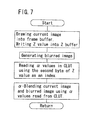
- Fig. 7 shows a schematic flow of the draw processing according to the embodiment. It should now be noted that the processing described below is such that being executed mainly by the pixel engine 6 using data stored in the image memory 7.
- the pixel engine 6 first in step S1 draws a current image (a first image in the present invention) into the frame buffer 10, and writes a Z value in the Z buffer 8.
- the current image herein comprises a "mountain” object 20, a "house” object 21 and a “human” object 22, where the "mountain” object 20 is placed most apart from a virtual viewpoint, the "human” object 22 is placed close to the virtual viewpoint, and the "house” object 21 is placed at an intermediate point therebetween, as shown in Fig. 8.
- a background image other than these objects is omitted herein for simplicity of the explanation.
- the pixel engine 6 next in step S2 generates a blurred image of the current image (a second image in the present invention), and stores such blurred image into another storage area in the frame buffer 10. It is now also allowable to provide a separate frame buffer beside the frame buffer 10 and store the blurred image into such separate frame buffer.
- a variety of techniques for producing the blurred image and one example of which is such that synthesizing the current image with a slightly shifted image thereof.
- the blurred image generated in step S2 is composed, for example, of a blurred image 23 of the "mountain” object 20 shown in Fig. 8, a blurred image 24 of the "house” object 21 and a blurred image 25 of the "human” object 22, as shown in Fig. 9.
- the degrees of the blurring of the blurred images 23, 24 and 25 are the same.
- the pixel engine 6 next in step S3 reads out the ⁇ value from the CLUT shown in Fig. 4 using the second byte of the Z value, written in the Z buffer 8, for the individual pixels in the current image shown in Fig. 8.
- the "mountain” object 20 is most apart from the virtual viewpoint, the "human” object 22 is most close to the virtual viewpoint, and the "house” object 21 is placed at an intermediate distance. So that the Z values for the individual pixels of the current image shown in Fig. 8 are largest for the pixels composing the "mountain” object 20, smallest for those composing the "human” object 22, and intermediate for the "house” object 21.
- the second byte of such Z value is used as an index for withdrawing the ⁇ value from the CLUT shown in Fig.
- the ⁇ value corresponding to the individual pixels is largest for those composing the "mountain” object 20 (maximum degree of semi-transparency), smallest for those composing the "human” object 22 (minimum degree of semi-transparency), and intermediate for those composing the "house” object 21 (intermediate degree of semi-transparency).
- step S4 proceeds the ⁇ -blending of the current image shown in Fig. 8 and the blurred image shown in Fig. 9, both of which being stored in the frame buffer 10, using an ⁇ plane composed of the ⁇ values read out in the process of step S3.
- the portion of the "mountain” object has the largest degree of semi-transparency, in which the blurred image accounts for a larger ratio than the current image, so that such object is drawn as a blurred image 26 as shown in Fig. 10.
- the portion of the "human” object has the smallest degree of semi-transparency, in which the current image accounts for a larger ratio than the blurred image, so that such object is drawn as an in-focal image 28.
- the portion of the "house” object has the intermediate degree of semi-transparency, so that such object is drawn as an image 27 not so well-focused than the image 28 but not so blurred than the image 26.
- a draw processing program used for the case that the draw processing by the pixel engine 6 is practiced on the software basis is such that sequentially executing the individual process steps explained referring to the flow chart of Fig. 7.
- Such draw processing program can not only be installed previously as a processing program for the pixel engine 6 , but can also be entered through the input terminal 13 shown in Fig. 1 at the same time with, or in advance of entering the polygon information.
- FIG. 11 shows a schematic constitution of a personal computer on which the draw processing program whose process flow was shown in Fig. 7 is run.
- the draw processing program is mainly executed by a CPU 123 shown in Fig. 11.
- a storage unit 128 comprises, for example, a hard disk and a driver therefore.
- the hard disk has stored therein an operating program; draw processing program 129 of this embodiment incorporated for example by installation from various recording media such as a CD-ROM and DVD-ROM, or downloading via a communication line; and various data 130 typically including graphic information for polygon drawing, texture, Z value, general texture, color value and ⁇ value.
- the communication unit 121 is a communication device responsible for data communication with the external, such as a modem allowing connection to an analogue public telephone line, a cable modem allowing connection to a cable television network, a terminal adaptor allowing connection to ISDN (Integrated Services Digital Network), and a modem allowing connection to ADSL (Asymmetric Digital Subscriber Line).
- a communication interface (I/F) unit 122 is an interface device responsible for protocol conversion which enables data exchange between the communication unit 121 and an internal bus.
- An input unit 131 is an input device such as a keyboard, mouse and touch pad.
- a user interface (I/F) unit 132 is an interface device for supplying signals from the input unit 133 to the internal unit.
- a drive unit 135 is a drive device capable of reading various data and programs including the draw processing program according to this embodiment from a recording medium such as a card-type semiconductor memory.
- a drive interface (I/F) unit 134 is an interface device for supplying signals from the drive unit 135 to the internal unit.
- a display unit 137 is a display device such as a CRT (cathode ray tube) or LCD (liquid crystal display).
- a display drive unit 136 is a drive device responsible for driving such display unit 137 for display.
- a ROM 124 typically comprises a re-loadable non-volatile memory such as a flash memory, and stores a BIOS (Basic Input/Output System) and various initial set values of the personal computer.
- a RAM 125 is a device into which application programs read out from the hard disk in the storage unit 128 or various data are loaded, and is used as a working RAM for the CPU 123.
- the CPU 123 controls the entire operations of the personal computer as well as executes the foregoing draw processing based on the operating system programs or the draw processing program 129 of this embodiment stored in the storage unit 128. That is, in the constitution shown in Fig. 11, The CPU 123 executes the draw processing program of this embodiment, which is one of the application programs read out from the hard disk of the storage unit 128 and loaded into the RAM 125, to thereby enable the draw processing described in the foregoing embodiment.
- the embodiment can provide an image in which an object or the like close to the virtual viewpoint is well focused and those apart from the virtual viewpoint are gradually blurred as the distance from such virtual viewpoint increases, where even objects or the like apart from the focal position retain the color to thereby attain a natural perspective.
- the perspective is achieved by ⁇ -blending the current image and a single blurred image using an ⁇ -plane comprising ⁇ values corresponding to the distances from the virtual viewpoint, so that the amount of image processing does not increase even when the distance from the virtual viewpoint is expressed in 256 steps (1 byte), which desirably ensures load reduction for CPU and speed-up of the processing.
- ⁇ -plane is also available for blending an arbitrary color with the current image, which produces an image in which the objects or the like seem to be fused into the arbitrary color as the distance from the viewpoint increases.
- Such technique is advantageous in achieving fogging, in which an object is more heavily fogged as the distance thereof from the viewpoint increases. It becomes also possible to create a special effect by ⁇ -blending an arbitrary image and the current image using such ⁇ -plane.
- ⁇ value was defined based on the Z value for every pixel in the above embodiment, it is still also allowable to define the ⁇ -value according to the distance from the virtual viewpoint for every polygon or object.
Landscapes
- Physics & Mathematics (AREA)
- Engineering & Computer Science (AREA)
- Geometry (AREA)
- Computer Graphics (AREA)
- General Physics & Mathematics (AREA)
- Theoretical Computer Science (AREA)
- Image Generation (AREA)
- Image Processing (AREA)
- Processing Or Creating Images (AREA)
Applications Claiming Priority (4)
| Application Number | Priority Date | Filing Date | Title |
|---|---|---|---|
| JP2000399461 | 2000-12-27 | ||
| JP2000399461 | 2000-12-27 | ||
| JP2001236325A JP3715222B2 (ja) | 2000-12-27 | 2001-08-03 | 描画方法、描画装置、描画処理プログラム、描画処理プログラムを記録した記録媒体、および描画処理プログラム実行装置 |
| JP2001236325 | 2001-08-03 |
Publications (2)
| Publication Number | Publication Date |
|---|---|
| EP1223559A2 true EP1223559A2 (fr) | 2002-07-17 |
| EP1223559A3 EP1223559A3 (fr) | 2004-10-20 |
Family
ID=26606957
Family Applications (1)
| Application Number | Title | Priority Date | Filing Date |
|---|---|---|---|
| EP01309140A Withdrawn EP1223559A3 (fr) | 2000-12-27 | 2001-10-29 | Procédé pour dessiner des lignes sur un écran bidimensionnel |
Country Status (5)
| Country | Link |
|---|---|
| US (1) | US7167600B2 (fr) |
| EP (1) | EP1223559A3 (fr) |
| JP (1) | JP3715222B2 (fr) |
| KR (1) | KR20020053708A (fr) |
| CN (1) | CN1267859C (fr) |
Cited By (2)
| Publication number | Priority date | Publication date | Assignee | Title |
|---|---|---|---|---|
| AT503743B1 (de) * | 2002-10-09 | 2008-05-15 | Vrvis Zentrum Fuer Virtual Rea | Verfahren zur rechnergestützten darstellung von objekten |
| EP3113160A1 (fr) * | 2015-06-30 | 2017-01-04 | Thomson Licensing | Procédé et dispositif pour le traitement d'une partie d'un contenu vidéo immersif selon la position de parties de référence |
Families Citing this family (17)
| Publication number | Priority date | Publication date | Assignee | Title |
|---|---|---|---|---|
| KR20030076904A (ko) * | 2002-03-23 | 2003-09-29 | (주)맥스소프트 | 중간 시점 영상 합성 방법 |
| JP3639286B2 (ja) * | 2003-09-25 | 2005-04-20 | コナミ株式会社 | ゲームプログラム、及びゲーム装置 |
| JP3993863B2 (ja) * | 2004-04-29 | 2007-10-17 | 株式会社コナミデジタルエンタテインメント | 画像生成装置、速度表現方法、および、プログラム |
| US7755678B2 (en) * | 2005-10-28 | 2010-07-13 | Hewlett-Packard Development Company, L.P. | Programmable anti-aliasing systems and methods for cameras |
| JP4749198B2 (ja) * | 2006-03-30 | 2011-08-17 | 株式会社バンダイナムコゲームス | プログラム、情報記憶媒体及び画像生成システム |
| KR100829564B1 (ko) | 2006-09-29 | 2008-05-14 | 삼성전자주식회사 | 효율적으로 모션 블러 효과를 제공하는 3차원 그래픽스렌더링 방법 및 장치 |
| JP4805094B2 (ja) * | 2006-10-31 | 2011-11-02 | 富士通セミコンダクター株式会社 | フォグ効果処理方法、グラフィックス装置、グラフィックス用半導体集積回路装置及びフォグ効果処理プログラム |
| JP4896761B2 (ja) * | 2007-02-16 | 2012-03-14 | 株式会社日立製作所 | 立体地図表示システム、立体地図の表示方法、及びそのプログラム |
| US20090080803A1 (en) * | 2007-09-20 | 2009-03-26 | Mitsugu Hara | Image processing program, computer-readable recording medium recording the program, image processing apparatus and image processing method |
| JP4847572B2 (ja) * | 2009-11-13 | 2011-12-28 | 株式会社コナミデジタルエンタテインメント | 画像処理装置、画像処理装置の制御方法、及びプログラム |
| JP5508878B2 (ja) * | 2010-01-29 | 2014-06-04 | 京楽産業.株式会社 | 遊技機、遊技機の演出方法及び演出プログラム |
| JP5483699B2 (ja) * | 2010-01-29 | 2014-05-07 | 京楽産業.株式会社 | 遊技機、遊技機の演出方法及び演出プログラム |
| JP5924833B2 (ja) * | 2011-09-22 | 2016-05-25 | シャープ株式会社 | 画像処理装置、画像処理方法、画像処理プログラム、及び撮像装置 |
| JP2019130148A (ja) * | 2018-01-31 | 2019-08-08 | 株式会社三洋物産 | 遊技機 |
| JP6407460B1 (ja) * | 2018-02-16 | 2018-10-17 | キヤノン株式会社 | 画像処理装置、画像処理方法およびプログラム |
| EP3836091B1 (fr) * | 2018-08-06 | 2025-11-26 | Sony Interactive Entertainment Inc. | Dispositif de décision de valeur alpha, procédé de décision de valeur alpha, programme et structure de données d'image |
| CN112087648B (zh) * | 2019-06-14 | 2022-02-25 | 腾讯科技(深圳)有限公司 | 图像处理方法、装置、电子设备及存储介质 |
Family Cites Families (17)
| Publication number | Priority date | Publication date | Assignee | Title |
|---|---|---|---|---|
| US5280357A (en) * | 1992-10-13 | 1994-01-18 | The Grass Valley Group, Inc. | Depth-based recursive video effects |
| JP2792376B2 (ja) | 1993-02-02 | 1998-09-03 | 松下電器産業株式会社 | 画像ぼかし処理装置 |
| JPH087124A (ja) | 1994-06-17 | 1996-01-12 | Hitachi Ltd | 映像模擬方式 |
| AUPM822294A0 (en) * | 1994-09-16 | 1994-10-13 | Canon Inc. | Colour blend system |
| GB9422089D0 (en) * | 1994-11-02 | 1994-12-21 | Philips Electronics Uk Ltd | Blurring for computer graphics |
| WO1996028794A1 (fr) * | 1995-03-10 | 1996-09-19 | Hitachi, Ltd. | Dispositif d'affichage graphique tridimensionnel |
| JP4291892B2 (ja) * | 1996-12-06 | 2009-07-08 | 株式会社セガ | 画像処理装置およびその方法 |
| JP3372832B2 (ja) | 1997-07-25 | 2003-02-04 | コナミ株式会社 | ゲーム装置、ゲーム画像処理方法およびゲーム画像処理プログラムを記録したコンピュータ読み取り可能な記録媒体 |
| JP3580682B2 (ja) * | 1997-09-26 | 2004-10-27 | 株式会社ソニー・コンピュータエンタテインメント | 画像処理装置および方法 |
| JPH11242753A (ja) | 1998-02-25 | 1999-09-07 | Hitachi Ltd | 3次元描画方法および装置 |
| US6266068B1 (en) * | 1998-03-13 | 2001-07-24 | Compaq Computer Corporation | Multi-layer image-based rendering for video synthesis |
| JP3668019B2 (ja) | 1998-10-27 | 2005-07-06 | 株式会社ソニー・コンピュータエンタテインメント | 記録媒体、画像処理装置および画像処理方法 |
| JP2000251090A (ja) | 1999-03-01 | 2000-09-14 | Sony Computer Entertainment Inc | 描画装置及び該描画装置で被写界深度を表現する方法 |
| JP3448536B2 (ja) | 1999-12-31 | 2003-09-22 | 株式会社スクウェア・エニックス | 三次元コンピュータ画像処理のプログラムを記録したコンピュータ読み取り可能な記録媒体、ぼかし描画処理方法およびビデオゲーム装置 |
| JP2001204964A (ja) * | 2000-01-28 | 2001-07-31 | Square Co Ltd | 球技用ゲームのプログラムを記録したコンピュータ読み取り可能な記録媒体および球技用ゲームの画像表示処理方法およびビデオゲーム装置 |
| JP4656616B2 (ja) | 2000-01-28 | 2011-03-23 | 株式会社バンダイナムコゲームス | ゲームシステム、プログラム及び情報記憶媒体 |
| JP3404347B2 (ja) * | 2000-01-28 | 2003-05-06 | 株式会社スクウェア | 3次元コンピュータ画像処理のプログラムを記録したコンピュータ読み取り可能な記録媒体およびぼかし描画処理方法 |
-
2001
- 2001-08-03 JP JP2001236325A patent/JP3715222B2/ja not_active Expired - Fee Related
- 2001-10-19 US US10/012,203 patent/US7167600B2/en not_active Expired - Fee Related
- 2001-10-29 EP EP01309140A patent/EP1223559A3/fr not_active Withdrawn
- 2001-11-15 KR KR1020010071070A patent/KR20020053708A/ko not_active Withdrawn
- 2001-11-23 CN CNB011393831A patent/CN1267859C/zh not_active Expired - Fee Related
Cited By (5)
| Publication number | Priority date | Publication date | Assignee | Title |
|---|---|---|---|---|
| AT503743B1 (de) * | 2002-10-09 | 2008-05-15 | Vrvis Zentrum Fuer Virtual Rea | Verfahren zur rechnergestützten darstellung von objekten |
| EP3113160A1 (fr) * | 2015-06-30 | 2017-01-04 | Thomson Licensing | Procédé et dispositif pour le traitement d'une partie d'un contenu vidéo immersif selon la position de parties de référence |
| EP3113159A1 (fr) * | 2015-06-30 | 2017-01-04 | Thomson Licensing | Procédé et dispositif pour le traitement d'une partie d'un contenu vidéo immersif selon la position de parties de référence |
| US10298903B2 (en) | 2015-06-30 | 2019-05-21 | Interdigital Ce Patent Holdings | Method and device for processing a part of an immersive video content according to the position of reference parts |
| RU2722584C2 (ru) * | 2015-06-30 | 2020-06-01 | Интердиджитал Се Пэйтент Холдингз | Способ и устройство обработки части видеосодержимого с погружением в соответствии с положением опорных частей |
Also Published As
| Publication number | Publication date |
|---|---|
| CN1267859C (zh) | 2006-08-02 |
| JP3715222B2 (ja) | 2005-11-09 |
| US20020089515A1 (en) | 2002-07-11 |
| JP2002260007A (ja) | 2002-09-13 |
| EP1223559A3 (fr) | 2004-10-20 |
| KR20020053708A (ko) | 2002-07-05 |
| CN1361506A (zh) | 2002-07-31 |
| US7167600B2 (en) | 2007-01-23 |
Similar Documents
| Publication | Publication Date | Title |
|---|---|---|
| US7167600B2 (en) | Drawing method for drawing image on two-dimensional screen | |
| US6876360B2 (en) | Image generation method and device used thereof | |
| JP3782709B2 (ja) | 画像生成の方法および装置 | |
| JP4399910B2 (ja) | ブレンディング処理を含む画像処理装置及びその方法 | |
| US7167596B2 (en) | Image processing method for generating three-dimensional images on a two-dimensional screen | |
| JP2001022343A (ja) | グラフィカル・オブジェクトのアンチエイリアシング化イメージング方法およびモジュール、およびナビゲーションシステム | |
| JP2004005567A (ja) | コンピュータディスプレイ画像を生成する方法ならびに画像データを生成するコンピュータ処理システムおよびグラフィックスプロセッサ | |
| US7499108B2 (en) | Image synthesis apparatus, electrical apparatus, image synthesis method, control program and computer-readable recording medium | |
| KR19990045321A (ko) | 폴리곤이 분할되는 화상처리 | |
| JP3527489B2 (ja) | 描画処理方法及び装置、描画処理プログラムを記録した記録媒体、描画処理プログラム | |
| US6833836B2 (en) | Image rendering process for displaying three-dimensional image information on a two-dimensional screen | |
| JPH07146931A (ja) | 画像創成方法 | |
| US6812931B2 (en) | Rendering process | |
| JP4797039B2 (ja) | 画像合成方法及び装置 | |
| CN114241101B (zh) | 三维场景渲染方法、系统、装置及存储介质 | |
| JP2007296218A (ja) | ゲーム画像処理プログラムおよびゲーム画像処理装置 | |
| US7079136B2 (en) | Rendering method of rendering image on two-dimensional screen | |
| JP2004240910A (ja) | 画像処理装置および画像処理方法 | |
| JPH10214352A (ja) | 画像生成装置及び画像生成方法 | |
| JP3382536B2 (ja) | 画像生成方法、画像生成装置および画像生成プログラムを記録した記録媒体 | |
| JP3170419B2 (ja) | 画像の影付け方法 | |
| JP5091372B2 (ja) | 画像表示装置 | |
| JP5459072B2 (ja) | 画像処理装置、画像処理方法、及び画像処理プログラム | |
| CN113192160A (zh) | 一种幻灯片切换效果的实现方法、存储介质和计算机 | |
| JP2004158032A (ja) | コンピュータに実行させるための描画処理プログラム、コンピュータに実行させるための描画処理プログラムを記録した記録媒体、プログラム実行装置、描画装置及び方法 |
Legal Events
| Date | Code | Title | Description |
|---|---|---|---|
| PUAI | Public reference made under article 153(3) epc to a published international application that has entered the european phase |
Free format text: ORIGINAL CODE: 0009012 |
|
| AK | Designated contracting states |
Kind code of ref document: A2 Designated state(s): AT BE CH CY DE DK ES FI FR GB GR IE IT LI LU MC NL PT SE TR |
|
| AX | Request for extension of the european patent |
Free format text: AL;LT;LV;MK;RO;SI |
|
| PUAL | Search report despatched |
Free format text: ORIGINAL CODE: 0009013 |
|
| AK | Designated contracting states |
Kind code of ref document: A3 Designated state(s): AT BE CH CY DE DK ES FI FR GB GR IE IT LI LU MC NL PT SE TR |
|
| AX | Request for extension of the european patent |
Extension state: AL LT LV MK RO SI |
|
| AKX | Designation fees paid | ||
| REG | Reference to a national code |
Ref country code: DE Ref legal event code: 8566 |
|
| STAA | Information on the status of an ep patent application or granted ep patent |
Free format text: STATUS: THE APPLICATION IS DEEMED TO BE WITHDRAWN |
|
| 18D | Application deemed to be withdrawn |
Effective date: 20050421 |