EP1223741A2 - Bildübertragungsverfahren und -Vorrichtung - Google Patents
Bildübertragungsverfahren und -Vorrichtung Download PDFInfo
- Publication number
- EP1223741A2 EP1223741A2 EP02075792A EP02075792A EP1223741A2 EP 1223741 A2 EP1223741 A2 EP 1223741A2 EP 02075792 A EP02075792 A EP 02075792A EP 02075792 A EP02075792 A EP 02075792A EP 1223741 A2 EP1223741 A2 EP 1223741A2
- Authority
- EP
- European Patent Office
- Prior art keywords
- data
- bus
- memory
- recording
- memory means
- Prior art date
- Legal status (The legal status is an assumption and is not a legal conclusion. Google has not performed a legal analysis and makes no representation as to the accuracy of the status listed.)
- Withdrawn
Links
Images



Classifications
-
- H—ELECTRICITY
- H04—ELECTRIC COMMUNICATION TECHNIQUE
- H04N—PICTORIAL COMMUNICATION, e.g. TELEVISION
- H04N1/00—Scanning, transmission or reproduction of documents or the like, e.g. facsimile transmission; Details thereof
- H04N1/32—Circuits or arrangements for control or supervision between transmitter and receiver or between image input and image output device, e.g. between a still-image camera and its memory or between a still-image camera and a printer device
- H04N1/32358—Circuits or arrangements for control or supervision between transmitter and receiver or between image input and image output device, e.g. between a still-image camera and its memory or between a still-image camera and a printer device using picture signal storage, e.g. at transmitter
- H04N1/32363—Circuits or arrangements for control or supervision between transmitter and receiver or between image input and image output device, e.g. between a still-image camera and its memory or between a still-image camera and a printer device using picture signal storage, e.g. at transmitter at the transmitter or at the receiver
- H04N1/32368—Functions of a still picture terminal memory associated with transmission
-
- G—PHYSICS
- G06—COMPUTING OR CALCULATING; COUNTING
- G06F—ELECTRIC DIGITAL DATA PROCESSING
- G06F13/00—Interconnection of, or transfer of information or other signals between, memories, input/output devices or central processing units
- G06F13/14—Handling requests for interconnection or transfer
- G06F13/16—Handling requests for interconnection or transfer for access to memory bus
- G06F13/1605—Handling requests for interconnection or transfer for access to memory bus based on arbitration
-
- H—ELECTRICITY
- H04—ELECTRIC COMMUNICATION TECHNIQUE
- H04N—PICTORIAL COMMUNICATION, e.g. TELEVISION
- H04N1/00—Scanning, transmission or reproduction of documents or the like, e.g. facsimile transmission; Details thereof
- H04N1/00127—Connection or combination of a still picture apparatus with another apparatus, e.g. for storage, processing or transmission of still picture signals or of information associated with a still picture
- H04N1/00278—Connection or combination of a still picture apparatus with another apparatus, e.g. for storage, processing or transmission of still picture signals or of information associated with a still picture with a printing apparatus, e.g. a laser beam printer
-
- H—ELECTRICITY
- H04—ELECTRIC COMMUNICATION TECHNIQUE
- H04N—PICTORIAL COMMUNICATION, e.g. TELEVISION
- H04N1/00—Scanning, transmission or reproduction of documents or the like, e.g. facsimile transmission; Details thereof
- H04N1/00912—Arrangements for controlling a still picture apparatus or components thereof not otherwise provided for
-
- H—ELECTRICITY
- H04—ELECTRIC COMMUNICATION TECHNIQUE
- H04N—PICTORIAL COMMUNICATION, e.g. TELEVISION
- H04N1/00—Scanning, transmission or reproduction of documents or the like, e.g. facsimile transmission; Details thereof
- H04N1/00912—Arrangements for controlling a still picture apparatus or components thereof not otherwise provided for
- H04N1/00915—Assigning priority to, or interrupting, a particular operation
-
- H—ELECTRICITY
- H04—ELECTRIC COMMUNICATION TECHNIQUE
- H04N—PICTORIAL COMMUNICATION, e.g. TELEVISION
- H04N1/00—Scanning, transmission or reproduction of documents or the like, e.g. facsimile transmission; Details thereof
- H04N1/32—Circuits or arrangements for control or supervision between transmitter and receiver or between image input and image output device, e.g. between a still-image camera and its memory or between a still-image camera and a printer device
- H04N1/32358—Circuits or arrangements for control or supervision between transmitter and receiver or between image input and image output device, e.g. between a still-image camera and its memory or between a still-image camera and a printer device using picture signal storage, e.g. at transmitter
- H04N1/32363—Circuits or arrangements for control or supervision between transmitter and receiver or between image input and image output device, e.g. between a still-image camera and its memory or between a still-image camera and a printer device using picture signal storage, e.g. at transmitter at the transmitter or at the receiver
-
- H—ELECTRICITY
- H04—ELECTRIC COMMUNICATION TECHNIQUE
- H04N—PICTORIAL COMMUNICATION, e.g. TELEVISION
- H04N1/00—Scanning, transmission or reproduction of documents or the like, e.g. facsimile transmission; Details thereof
- H04N1/32—Circuits or arrangements for control or supervision between transmitter and receiver or between image input and image output device, e.g. between a still-image camera and its memory or between a still-image camera and a printer device
- H04N1/32358—Circuits or arrangements for control or supervision between transmitter and receiver or between image input and image output device, e.g. between a still-image camera and its memory or between a still-image camera and a printer device using picture signal storage, e.g. at transmitter
- H04N1/32363—Circuits or arrangements for control or supervision between transmitter and receiver or between image input and image output device, e.g. between a still-image camera and its memory or between a still-image camera and a printer device using picture signal storage, e.g. at transmitter at the transmitter or at the receiver
- H04N1/32379—Functions of a still picture terminal memory associated with reception
-
- H—ELECTRICITY
- H04—ELECTRIC COMMUNICATION TECHNIQUE
- H04N—PICTORIAL COMMUNICATION, e.g. TELEVISION
- H04N1/00—Scanning, transmission or reproduction of documents or the like, e.g. facsimile transmission; Details thereof
- H04N1/32—Circuits or arrangements for control or supervision between transmitter and receiver or between image input and image output device, e.g. between a still-image camera and its memory or between a still-image camera and a printer device
- H04N1/32502—Circuits or arrangements for control or supervision between transmitter and receiver or between image input and image output device, e.g. between a still-image camera and its memory or between a still-image camera and a printer device in systems having a plurality of input or output devices
- H04N1/32507—Circuits or arrangements for control or supervision between transmitter and receiver or between image input and image output device, e.g. between a still-image camera and its memory or between a still-image camera and a printer device in systems having a plurality of input or output devices a plurality of input devices
- H04N1/32512—Circuits or arrangements for control or supervision between transmitter and receiver or between image input and image output device, e.g. between a still-image camera and its memory or between a still-image camera and a printer device in systems having a plurality of input or output devices a plurality of input devices of different type, e.g. internal and external devices
-
- H—ELECTRICITY
- H04—ELECTRIC COMMUNICATION TECHNIQUE
- H04N—PICTORIAL COMMUNICATION, e.g. TELEVISION
- H04N1/00—Scanning, transmission or reproduction of documents or the like, e.g. facsimile transmission; Details thereof
- H04N1/32—Circuits or arrangements for control or supervision between transmitter and receiver or between image input and image output device, e.g. between a still-image camera and its memory or between a still-image camera and a printer device
- H04N1/32561—Circuits or arrangements for control or supervision between transmitter and receiver or between image input and image output device, e.g. between a still-image camera and its memory or between a still-image camera and a printer device using a programmed control device, e.g. a microprocessor
- H04N1/32593—Using a plurality of controllers, e.g. for controlling different interfaces
-
- H—ELECTRICITY
- H04—ELECTRIC COMMUNICATION TECHNIQUE
- H04N—PICTORIAL COMMUNICATION, e.g. TELEVISION
- H04N1/00—Scanning, transmission or reproduction of documents or the like, e.g. facsimile transmission; Details thereof
- H04N1/32—Circuits or arrangements for control or supervision between transmitter and receiver or between image input and image output device, e.g. between a still-image camera and its memory or between a still-image camera and a printer device
- H04N1/32561—Circuits or arrangements for control or supervision between transmitter and receiver or between image input and image output device, e.g. between a still-image camera and its memory or between a still-image camera and a printer device using a programmed control device, e.g. a microprocessor
- H04N1/32598—Bus based systems
- H04N1/32603—Multi-bus systems
-
- H—ELECTRICITY
- H04—ELECTRIC COMMUNICATION TECHNIQUE
- H04N—PICTORIAL COMMUNICATION, e.g. TELEVISION
- H04N1/00—Scanning, transmission or reproduction of documents or the like, e.g. facsimile transmission; Details thereof
- H04N1/00127—Connection or combination of a still picture apparatus with another apparatus, e.g. for storage, processing or transmission of still picture signals or of information associated with a still picture
- H04N1/00204—Connection or combination of a still picture apparatus with another apparatus, e.g. for storage, processing or transmission of still picture signals or of information associated with a still picture with a digital computer or a digital computer system, e.g. an internet server
-
- H—ELECTRICITY
- H04—ELECTRIC COMMUNICATION TECHNIQUE
- H04N—PICTORIAL COMMUNICATION, e.g. TELEVISION
- H04N2201/00—Indexing scheme relating to scanning, transmission or reproduction of documents or the like, and to details thereof
- H04N2201/0008—Connection or combination of a still picture apparatus with another apparatus
- H04N2201/001—Sharing resources, e.g. processing power or memory, with a connected apparatus or enhancing the capability of the still picture apparatus
-
- H—ELECTRICITY
- H04—ELECTRIC COMMUNICATION TECHNIQUE
- H04N—PICTORIAL COMMUNICATION, e.g. TELEVISION
- H04N2201/00—Indexing scheme relating to scanning, transmission or reproduction of documents or the like, and to details thereof
- H04N2201/0077—Types of the still picture apparatus
- H04N2201/0082—Image hardcopy reproducer
-
- H—ELECTRICITY
- H04—ELECTRIC COMMUNICATION TECHNIQUE
- H04N—PICTORIAL COMMUNICATION, e.g. TELEVISION
- H04N2201/00—Indexing scheme relating to scanning, transmission or reproduction of documents or the like, and to details thereof
- H04N2201/0077—Types of the still picture apparatus
- H04N2201/0086—Image transceiver
-
- H—ELECTRICITY
- H04—ELECTRIC COMMUNICATION TECHNIQUE
- H04N—PICTORIAL COMMUNICATION, e.g. TELEVISION
- H04N2201/00—Indexing scheme relating to scanning, transmission or reproduction of documents or the like, and to details thereof
- H04N2201/32—Circuits or arrangements for control or supervision between transmitter and receiver or between image input and image output device, e.g. between a still-image camera and its memory or between a still-image camera and a printer device
- H04N2201/3285—Circuits or arrangements for control or supervision between transmitter and receiver or between image input and image output device, e.g. between a still-image camera and its memory or between a still-image camera and a printer device using picture signal storage, e.g. at transmitter
- H04N2201/3297—Simultaneous use of a single memory for different image storage purposes
Definitions
- the present invention relates to an image communication method and apparatus.
- Fig. 10 is a block diagram illustrating the construction of a general facsimile apparatus having an ink-jet printer as a recording apparatus.
- numeral 200a is a facsimile controller system
- numeral 200b is an ink-jet printer system.
- data transmitted from the facsimile controller system 200a is received by the ink-jet printer system 200b, and the image data for recording included in the received data is printed on a recording medium.
- Numeral 200 is a facsimile controller (FAX controller) which performs reading of an original image, transmission/reception control to a telephone communication line, and data transmission and recording instructions to an ink-jet printer system 200b.
- Numeral 201 is a memory for the facsimile controller system which stores read data of an original or reception data received from the telephone communication line. That is, the FAX controller 200 performs the operation instruction to an ink-jet printer system 200b via a serial interface 202, and supervises the state of the ink-jet printer system 200b such as an error caused by out-of-paper.
- Numeral 203 is an interface circuit for printer data (printer interface), and transmits a control code and image data to execute recording with respect to the ink-jet printer system 200b.
- printer interface 203 there is a CENTRONICS interface which is generally by a printer controller.
- numeral 210 is a printer CPU which performs various controls in the ink-jet printer system 200b.
- Numeral 211 is a memory for the ink-jet printer system 200b which stores data received from a facsimile controller system 200a.
- Numeral 212 is a serial interface which receives the operation instruction transmitted from the facsimile controller system 200a. Furthermore, the serial interface 212 transmits the facsimile controller system 200a from the instruction of the ink-jet printer system 200b.
- Numeral 213 is an interface circuit for print data (printer interface) which receives a control code and image data transmitted from the facsimile controller system 200a.
- Numeral 214 is a register block capable of reading and writing. The Printer CPU 210 writes the received image data into the register block 214, and converts the written image data to correspond to the recording form of a printer head 216, and then outputs it. The printer CPU 210 can read the converted result.
- Numeral 215 is a head controller of the ink-jet printer which is initialized by the instruction of the printer CPU 210.
- the head controller 215 fetches recording data out of the memory 211, and performs transmission of recording data and recording control to the ink-jet head 216.
- the ink-jet head 216 performs recording in accordance with the control of the head controller 215.
- Numeral 217 is a carriage motor, and numeral 218 is a line feed motor. These motors are respectively driven by a control signal of the printer CPU 210.
- the facsimile controller 200 sequentially supervises the state of the ink-jet printer system 200b by the serial interface 202 or the printer interface 203. When it is determined that the ink-jet printer system 200b is in the standby state, the image data which is a result of original read or a result of data reception is stored in the memory 201. If a predetermined amount of image data is stored in the memory 201, the facsimile controller 200 transmits the recording start instruction to the ink-jet printer system 200b.
- the ink-jet printer system 200b starts receiving data from the facsimile controller system 200a by the instruction. That is, the data transmitted from the printer interface 203 is received by the printer interface 213, and sequentially stores in the memory 211.
- the printer CPU 210 supervises this, and fetches the data when the predetermined amount of data is stored in the memory 211. Subsequently, the printer CPU 210 deletes data which is unnecessary for recording, and converts the remaining data into the recording data for ink-jet recording by the register block 214.
- the recording data generated in this way is stored in a predetermined recording data area in the memory 211 which is reserved as a print buffer.
- the ink-jet head 216 After the recording data storage, the ink-jet head 216 starts recording.
- the printer CPU 210 performs recording processing at a predetermined timing. At the recording timing, the printer CPU 210 sets recording control data obtained from the result by referring to an ambient temperature, humidity and history of past recording data stored in the head controller 215, and then transmits a recording start signal. At the same time, the printer CPU 210 transmits control signals to the carriage motor 217 and line feed motor 218 respectively.
- the head controller 215 to which the recording start signal is transmitted from the printer CPU 210 reads the recording data out of the recording data area of the memory 211, drives the ink-jet head 216 in accordance with the predetermined recording control data, and performs recording on the recording medium.
- the above-described general facsimile apparatus performs interface between the facsimile controller system 200a and the ink-jet printer system 200b by an printer interface. Accordingly, the facsimile controller system 200a and the ink-jet printer system 200b respectively require a printer interface circuit, serial interface circuit and data storage memory. This causes a problem to minimize an apparatus and reduce its cost.
- the above-described facsimile apparatus does not include a function to receive data transmitted from a personal computer, storage, recording or transmission to a telephone communication line of the data transmitted from the personal computer via the printer interface could not be processed.
- an image communication apparatus comprising: reception means for storing data received from an external apparatus in a memory means via a first bus; recording means for fetching the data stored in the memory means via a second bus connected to the memory means, and recording an image based on the data; and switching means for switching an address for access to the memory means corresponding to the access request to the memory means by the reception means and the recording means, and switching the connection of the first bus and second bus which are connected to the memory means.
- the present invention provides an image communication method comprising: a connection step of connecting a first bus to a memory means; a reception step of storing data received from an external apparatus in the memory means via the first bus; switching step of switching the bus to be connected to the memory means from the first bus to the second bus; and a recording step of fetching the data stored in the memory means via the second bus connected to the memory means, and recording an image based on the data.
- the reception means stores data received from an external apparatus to a memory means via a first bus.
- the recording means for recording received data fetches the data from the memory means via a second bus, and performs a recording based on the data. Furthermore, an access address to the memory means is switched, and the connection between the memory means and the first or second bus is switched, in accordance with the execution of the reception means and recording means. Accordingly, a memory of the reception means (for example, the facsimile system), and a memory of the recording means (for example, the printer system), are incorporated, and an interface between these systems is not needed.
- An embodiment of the present invention provides an image communication apparatus comprising:
- An embodiment of the present invention comprises an image communication method comprising: a communication step of accessing a memory means via a first bus to perform transmission/reception with an external apparatus, and performing data writing/data reading to/from the memory means; a recording step of fetching the data stored in the memory means and recording an image based on the data; an interface step of performing either transmission to other external apparatus or writing/reading of received data with respect to the memory means via a third bus connecting to the memory means for connecting to other external apparatus; and a switching step of switching the connection for switching an address of access to the memory means, and selecting a bus to be connected to the memory means from the first bus, second bus and third bus, in accordance with the access to the memory means by the communication step, recording step and external interface step.
- interface means connecting the external apparatus to a memory means via a third bus is included, and for example, data received from the external apparatus is stored in the memory means.
- Switching means switches an access address to the memory means in accordance with the access to the memory means by the reception means, recording means and external interface means, and switches the connection of a bus by selecting a bus to be connected from the first, second and third bus.
- a memory of the reception means for example, facsimile system
- a memory of the recording means for example, printer system
- a memory of the interface means are incorporated, and, for example, an output of the data inputted via the printer interface to a communication line and recording on a recording medium are possible.
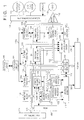
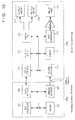
- Fig. 1 is a block diagram illustrating the construction of an ink-jet printer facsimile system according to the embodiment.
- numeral 100 is a FAX controller which performs reading of an original, transmission/reception control to a telephone communication line, and data transmission and recording instruction to a recording system in a similar manner as the above-described FAX controller 200.
- the FAX controller 100 outputs read data and received data to a data bus 120, and outputs a memory address signal to the data bus 120 in the same time division as these data.
- Numeral 101 is a memory which stores the original data, received data from the telephone communication line, recording data for the ink-jet printer and transmission data from an external device 190.
- Numeral 102 is an address latch circuit which latches address information outputted in the same time division as various data in the data bus 120 from the FAX controller 100 as FAX controller address.
- Numeral 103a is a register for system control capable of data writing and data reading by the FAX controller 100. Based on the written data in the register 103a, a capacity set switching signal 143 to switch the capacity setting in the memory 101 arranged on the address of the FAX controller 100, and a capacity switching signal 144 to switch the capacity of the ROM 180 arranged on the address of the FAX controller 100 are outputted to a memory request circuit 103.
- the memory request circuit 103 is connected to the capacity set switching signal 144 of the memory 101, a capacity switching signal of the ROM 180, and FAX controller address 125 which is an output address of the FAX controller.
- the memory request circuit 103 sequentially supervises the FAX controller address 125, and generates a memory request signal 130 when the FAX controller 100 detects an access to the memory 101. Furthermore, the memory request circuit 103 generates an access signal (ROM access signal 140) to the ROM 180 when the FAX controller 100 accesses the ROM 180.
- the condition determination of time-division address signal of the FAX controller 100 is changed based on the output of the capacity set switching signal 143 of the memory 101 and a capacity switching signal of the ROM 180. That is, the FAX controller address can be changed by each of the switching signals 143 and 144.
- each capacity of the ROM 180 and the memory 101 can be flexibly set according to the system.
- Numeral 104 is a refresh controller of the memory 101.
- the refresh controller 104 counts a ROM access signal 140 outputted from the memory request circuit 103. When a predetermined count value is reached, the counter is reset, and the counting is started again, and a refresh request signal 131 is outputted.
- Numeral 105a is a register for an external interface (external register), which is connected to a data bus 120.
- the FAX controller 100 performs setting of interface information such as interface permission and selection for the external register 105a in order to execute data communication with the externally connected data device (external device 190), and reads the interface information received from the external device 190 outputted from the external register 105a.
- Numeral 105 is an external controller which performs data interface with the external device 190 by an external interface setting signal 132, and outputs the interface state as the external interface setting signal 132. Furthermore, the external controller 105 outputs a memory request signal 134, and performs a memory request to the memory intervention circuit 109, when the memory access request is generated to the memory 101 from the external device 190.
- Numeral 191 is an interface circuit for communication with the external device via an interface, such as CENTRONICS interface or RS 232C interface.
- the interface circuit 191 is selected based on the interface information set by the external register 105a.
- Numeral 106 is a recording control CPU in an ink-jet type, which performs a recording processing at a predetermined timing in the similar to the printer CPU 210 in the above-described ink-jet system.
- Numeral 107 is a recording register which stores status information in each unit concerning ink-jet recording.
- the recording control CPU 106 sets recording control data with reference to the ambient temperature, humidity and history of past recording data, subsequently the recording system is properly operated and in the recording queued state from the ink-remaining-amount detection, recording-paper-remaining-amount detection, and the content of the recording register 107 including the recording operation state from the print data controller 108, a recording start signal is transmitted.
- recording control data is data to determine recording time of the ink-jet, timing, and order of applying recording current of the recording control data.
- the recording control data is set by the recording CPU 106 and stored in the recording register 107.
- the above-described recording control data, recording start signal, ink-remaining-amount detection information, recording-paper-remaining-amount detection information, and signal of the operation status of the print data controller 108 are communicated between the recording register 107 and the recording control CPU 106 via the data bus 124. Furthermore, the ink-remaining-detection information, the recording-paper-remaining-amount detection, and the recording state of the print data controller 108 are outputted as a printer status signal 135a, and inputted into the FAX controller 100 via the external register 105a.
- the recording control data such as recording time, cycle and applying order are outputted to the print controller 108 as a print interface signal 135.
- the FAX controller 100 performs recording processing at the start of recording, after the ink-remaining-amount detection information, the recording-paper-remaining-amount detection information, and the recording state of the print data controller 108 are confirmed.
- Numeral 108 is a print data controller which outputs the state of recording operation to the recording register 107, and a recording control signal 136 and a memory request signal 137 the state of the recording operation to the recording register 107 to perform controls such as the recording time of the ink-jet head, the timing, the reputation of the recording operation and the continuous recording with reference to the recording control data (an ink-jet printer interface signal 135) set in the recording register 107 by the recording start signal.
- Numeral 111a is a dot counter which counts recording data. The recording control CPU 106 reads out the count value from the dot counter 111a, and uses the count value as reference data when recording control data is calculated.
- Numeral 111 is a recording control circuit which transmits printing signals to the ink-jet head such that a pulse recording signal in time division is transmitted to the head driver 112 in accordance with the recording data fetched out of the memory 101.
- Numeral 109 is a memory intervention circuit which is connected to memory access signals 130, 134, 137, a refresh require signal 131 and a ROM access signal 140.
- the memory intervention circuit 109 outputs the data bus selection signal 142 to the data bus selector 110 in accordance with the above-described various signals.
- the memory intervention circuit 109 outputs memory line address signal, memory string address signal, and memory read/write signal which are required for reading/writing and refreshing operation to the memory 101 through signal lines 139 in a predetermined sequence. The status of each signal on the signal lines 139 for the access to the memory 101 is described later with reference to Fig. 4.
- the data bus selector 110 is connected to a data bus 120 which performs data interface with the FAX controller 100, the data bus 121 for the interface which communicates with the external device 190, connected to the recording data bus 122 and the data bus selection signal 142.
- the data bus selector 110 selects a data bus to be connected to the memory 101 in each memory access by the above-described data bus based on the content of the data bus selection signal 142, switches the data bus, and performs input/output of the memory 101.
- Numeral 116 is an external device address register which sets a memory address for an external interface.
- the external device address register 116 is connected to the data bus 120 of the FAX controller 100, and can be written or read out by the FAX controller 100.
- the set address data 126 is outputted as an address signal 138 of the memory 101 via the address selector 118 (to be described later).
- the data stored in the external device register 116 (that is, a memory address for the external device) is updated at each access of the memory 101.
- Numeral 117 is a recording address register which sets a memory address for recording data used by the recording control circuit 111.
- the recording address register 117 connected to the data bus 120 of the FAX controller 100 can be written and read out by the FAX controller 100.
- the selection address data 127 is outputted as an address signal 138 of the memory 101 via the address selector 118 (to be described later).
- the data stored in the recording address register 117 (that is, address for recording) is updated by each access of the memory 101.
- Numeral 118 is an address selector which determines an accessing address to the memory 101 as an address signal 138.
- the address selector 118 inputs a FAX controller address 125 by the FAX controller 100, a memory address for the external interface data 126, and a memory address 127 for recording data, selects a single address based on a data bus selection signal 142 (to be described later), and outputs the selected address to the memory 101.
- Numeral 112 is a head driver which drives an ink-jet head.
- the head driver 112 amplifies a pulse recording signal which is transmitted in time division by the recording control circuit 111 for performing recording control of the ink-jet head, and drives the ink-jet head 113.
- the ink-jet head 113 executes a recording operation in accordance with the head driver 112.
- Numeral 114 is a carriage motor for the recording head, and numeral 115 is a line feed motor for recording-paper-transferring. These motors are respectively operated in accordance with the control signal from the recording control CPU 106 for the ink-jet recording.
- Numeral 119 is a register block capable of being read or written by the FAX controller 100.
- the FAX controller 100 writes the image data in the register block 119.
- the stored image data is converted and outputted to correspond to the recording form of the ink-jet head 113, and the FAX controller 100 obtains the conversion result by reading the content of the register block 119.
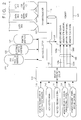
- Fig. 2 is a diagram for explaining the connection of the signals of the memory intervene circuit 109 and the memory 101.
- the circuit 109 When the memory intervene circuit 109 receives the memory request signals 130, 134, 137, the circuit 109 outputs a data bus selection signal 142 instructing to select an address and a bus with respect to the address selector 118 and data bus selector 110.
- the data bus selection signal 142 is outputted to the address selector 118 and the data bus selector 110 to select the FAX controller address 125 and the address bus 120 for the FAX controller 100.
- the signal line 139 is comprised of a memory-line signal line 139a, memory-string signal line 139b, memory write signal line 139c and memory read signal line 139d.
- the signal line 139 turns each signal on/off at. the predetermined timing according to whether the input memory request signal is a write request or a read request signal, and the writing or the reading operation of the memory 101 is executed.
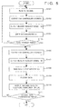
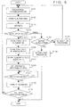
- the operation of the memory intervention circuit 109 is further described in detail with reference to Figs. 3A and 3B.
- the sequence operation of the memory intervention circuit 109 is shown in Figs. 3A and 3B, and the state of output signal from the memory intervention circuit 109 is shown in Fig. 4.
- step S1 whether or not a memory request signal 130 is generated is checked.
- step S2 whether or not the content of the memory request signal is a write request is determined. If so, the process proceeds to step S3, while if not, the process proceeds to step S23.
- step S3 the address selector 118 selects an address of the address latch circuit 102 by the data bus selection signal 142, and selects the data bus 120.
- step S4 the memory intervention circuit 109 waits for completion of the access and a writable state if the access to the memory 101 is during execution.
- the write operation is divided into six states as shown in Fig. 4.
- step S5 the state is changed to W1.
- the state W1 is a state where the memory line address in the address signal 138 is confirmed by the data bus selection signal 142, as shown in Fig. 4.
- step S5 to step S15 the state is sequentially changed from W1 to W6 of Fig. 4, and the write operation is completed at W6.
- state W2 and W4 the column of "data selection” is "valid”, and the data bus selection is validated by the data bus selection signal 142.
- the data bus 120 is connected to the memory 101, and the data on the data bus 120 is inputted into the memory 101.
- step S24 the memory intervene circuit 109 waits for that the access of the memory 101 during execution is completed, and that the state becomes being ready for accessing (state R1).
- the read operation is divided into six states as shown in Fig. 4.
- the state is changed to R1 where the memory line address is validated on the address signal 138 by the data bus selection signal 142.
- the state is sequentially changed from R1 to R6 by executing the processing from step S24 to step S35.
- the read operation is completed at state R6.
- step S1 the process proceeds from step S1 to S16 where whether or not the memory request signal 134 from outside is generated is determined. If generated, the process proceeds to step S3 where the sequence operation output which is similar to the write/read operation when the memory request signal is generated is performed.
- step S16 Since a memory request signal is not generated at step S1, the process proceeds step S16. Since a memory request signal from the outside is not generated, the process proceeds from step S16 to step S20. At step S20, whether or not the access signal 140 to the ROM 180 is generated is determined. If the access signal 140 is generated, the process proceeds to step S21, while if not, the present processing is ended. At step S21, whether or not the refresh request signal 131 is generated is determined. If generated, the process proceeds to step S40, while if not, the process proceeds to step S22.
- the memory intervene circuit 109 waits for the state such that the access to the memory 101 is completed and the next memory access becomes ready (the state can be changed to F1).
- the refresh operation is divided into five states (F1-F5).
- the process proceeds to step S41 where the state is changed to F1 by validating a memory line signal.
- the state is changed from F1 to F5 in steps S42 to S49, and thus, the refresh operation is completed at state F5.
- step S21 If a refresh signal is not detected at step S21, the process proceeds to step S22 where whether or not a memory request signal 137 is generated from the print data controller 108 is determined. If the memory request signal 137 is generated, the process proceeds to step S23. Subsequently, the memory intervene circuit 109 performs the operation output of various signals by the similar sequence to the read operation by the memory request signal 130.
- the operation sequence (Fig. 4) at the writing, reading and refreshing to the memory 101 is an example where the memory 101 is comprised of a DRAM. Accordingly, if the memory 101 is comprised of a SRAM, a line address and a string address are not needed for access, and an access to the memory 101 can be performed by a single address.
- a case where a memory request signal 130 from the FAX controller and a memory request signal 134 from the external device 190 are simultaneously generated is described.
- the sequence operation output when only the memory request signal 130 is inputted is first performed.
- the request signal 134 from the external device 190 is in queued state until the sequence operation ends.
- the refresh controller 104 supervises an access signal 140 to the ROM 180 outputted from the memory request circuit 103.
- the refresh request signal 131 is outputted from the refresh controller 104 only when the FAX controller 100 has accessed the address of the ROM 180 is detected. Accordingly, the refresh request signal 131 is not generated at the same time as the memory request signals 130, 134.
- the memory request signal 137 outputted from the print controller 108 may be generated at the same time as the memory request signals 130, 134 between the input of a recording start signal and the end of recording (the next recording queued state).
- the memory intervene circuit 109 accepts a memory request when the ROM access signal 140 is "valid" and the refresh request signal 131 is "invalid". Accordingly, when the memory request signal 130 or 134 is generated, the memory intervene circuit 109 becomes queued to the memory request signal 137.
- a data bus selection signal 142 is outputted from the memory intervene circuit 109.
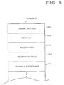
- Fig. 9 is a diagram illustrating the memory allocation of the memory 101 of the present embodiment.
- numeral 101a is an original data area which stores image data of the original read by a scanner.
- Numeral 101b is a buffer area which temporary stores coded data received via a communication line.
- Numeral 101c is an image data area which stores image data obtained by decoding the coded data in the buffer area 101b.
- Numeral 101d is a recording data area which stores recording data obtained by converting the image data to data appropriate for the ink-jet recording operation by the register block 119.
- Numeral 101e is a data area capable of being accessed by the external device 190.
- the FAX controller 100 performs reading control of an original and obtains the data.
- the image data is stored in a predetermined area on the memory 101 (the original data area 101a).
- step S102 when the FAX controller 100 outputs the address on the memory 101 which designates the data to the data bus 120 in the time division, the address latch circuit 102 latches and outputs the data as a FAX controller address 125.
- the memory request circuit 103 receives the data, detects an access request to the memory 101 of the FAX controller 100, and outputs a memory request signal 130.
- the memory intervene circuit 109 executes the memory access sequence operation described in Figs. 3A and 3B, and the image data is written in the memory 101.
- the memory intervene circuit 109 transmits a data bus selection signal 142 which selects a data bus 120 of the FAX controller 100 to the data bus selector 110 and the address selector 118. Accordingly, the address selector 118 selects and outputs a FAX controller address 125, and the data bus selector 110 outputs the data on the data bus 120 for the FAX controller to the memory 101.
- the image data is stored in the memory 101 by the memory access signal which is outputted while the output state of the memory intervene circuit 109 is sequentially changed from W1 to W6.
- step S105 whether or not the storage of the image data has ended is determined. If not, the process returns to step S101. On the other hand, if ended, the process proceeds to step S106 where the FAX controller 100 transmits the image data in the memory 101 stored in the above-described way to the telephone communication line in the following procedure.
- the memory address signal outputted from the FAX controller 100 in the time division is latched by the address latch circuit 102.
- the selection of the memory 101 is detected by the latched address, and the memory request circuit 103 outputs a memory request signal 130.
- the memory intervene circuit 109 performs the memory access sequence operation (Figs. 3A and 3B), and reads the (read) image data from the memory 101. That is, the memory intervene circuit 109 transmits a signal which selects the address 125 for the FAX controller 100 to the address selector 118 and a signal which selects the data bus 120 of the FAX controller 100 to the data bus selector 110.
- the data bus selector 110 outputs the data read from the memory 101 to the data bus 120 for FAX controller.
- the FAX controller 100 compresses the data read from the memory 101, and transmits the compressed data to a telephone communication circuit at step S110.
- step S121 the data received from the telephone communication line is stored in the buffer area 101b reserved in the memory 101 at step S122, and decoded at step S123.
- step S124 a data error check is performed on each line or communication frame. Note that the data storage procedure at step S122 is similar to the access to the memory 101 of the FAX controller 100.
- step S132 When a data error has occurred, the process proceeds to step S132 where whether or not the data is one during the re-reception is determined. If not, the re-reception processing is performed on the data by the CCITT communication regulation at step S133. When the data error still remains, the process proceeds from step S132 to step 134 where the communication is interrupted in accordance with the above-described communication regulation.
- the FAX controller 100 starts the recording operation.
- the FAX controller 100 fetches the image data stored in the image data area 101c of the memory 101, and writes the fetched image data in the register block 119.
- the register block 119 After a recording data conversion which is appropriate to the recording operation of the ink-jet head is executed, the converted data is read out and stored in the recording data area 101d in the memory 101.
- the FAX controller 100 sets the memory address for recording data in the recording address register 117 to set the memory address for recording data.
- whether or not a status signal of the ink-jet printer is in the recording queued is determined. If so, the recording instruction is performed at step S130.
- the recording control CPU 106 determines whether or not the recording start instruction is outputted from the FAX controller 100 via the recording register 107. If the recording start instruction is outputted, the process proceeds to step S141.
- the recording CPU 106 performs the recording processing at a predetermined timing.
- the recording CPU 106 confirms in each recording timing that the printer system is properly operated and in a queued state (at step S141), and sets the recording control data obtained with reference to the ambient temperature, humidity and history of past recording data, and then a recording start signal is transmitted.
- a signal indicating that the controller 108 is in the recording operation with the ink-jet recording register 107 is outputted at step S144.
- the output signal 135a of the recording register 107 receives this signal and its output is changed from the recording queued to the in recording operation.
- the print data controller 108 outputs a memory request signal 137 to the memory intervene circuit 109.
- the memory intervene circuit 109 receives this signal, and reads the converted data from the recording data area 101d of the memory 101. That is, the above-described memory access sequence operation is performed at the timing when the access signal 140 to the ROM 180 of the FAX controller 100 is "valid", and the refresh request signal 131 is "invalid", and a signal to select a recording data memory address 127 (recording data area address) is transmitted to the address selector 118 and a signal to select the recording data bus 122 is transmitted to the data us selector 111. Accordingly, the data bus selector 110 outputs the recording data in the memory 101 to the data bus 122 for recording.
- the recording control circuit 111 receives this data and transmits a pulse recording signal in the time division to the head driver 112 in accordance with the recording control signal 136 of the print data controller 108.
- the head driver 112 amplifies the pulse signal in the time division, and drives the ink-jet head 113.
- the recording CPU 106 respectively outputs a motor drive signal of the carriage motor 114 for the ink-jet head drive control and recording, and a motor drive signal of the line feed motor 115 for recording paper.
- step S148 the end of recording is waited. If ended, the process proceeds to step S149 where the indication of queued state is outputted. Returning to Fig. 6, whether or not the processing on all data is ended is determined at step S131. If not, the process returns to step S121, while if ended, the present processing ends. As described above, the recording of the (received) data stored in the memory 101 is performed, and the reception processing ends.
- the FAX controller 100 performs the recording control of an original, and stores the read data in the area (the original data area 101a) on the memory address for the FAX controller. Each area is divided in the memory 101 in advance.
- the storage procedure is similar to that of the read data storage in the transmission operation (steps S101-S105), the description is not repeated.
- the FAX controller 100 When the data is stored, the FAX controller 100 starts the recording operation. The FAX controller 100 fetches the read data stored in the memory 101, and writes the fetched data in the register block 119. Subsequently, the converted data for the ink-jet head is read out of the register block 119, and stored in the recording data area 101d of the memory 101. The FAX controller 100 transmits the recording instruction after the recording data has been stored.
- the recording control CPU 106 performs the control of the recording data, the carriage motor 114 and the line feed motor 115 is performed until the data stored in the memory 101 has been recorded.
- the detail of the present operation is a similar to the above-described recording operation at the reception operation, the description is not repeated.
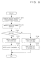
- step S151 when the memory access request is generated from the external device 190, at step S152, the external controller 105 outputs the memory request signal 134 to the memory intervene circuit 109.
- step S153 the memory intervene circuit 109 determines whether the memory request signal 134 is for write request or a read request . If it is for write request, the process proceeds to step S154, while if not, the process proceeds to step S156.
- the address selector 118 selects the content of the external device address register 116 by the data bus selection signal 142, and outputs this content as an address signal 138. Furthermore, the data bus selector 110 selects the data bus 121 for the external device by the data bus selection signal 142, and connects to the memory 101. At step S155, the data writing to the external device data area 101e in the memory 101 is executed.
- step S153 if it is not write request, the process proceeds to step S156 where the selection and switching of address and data bus are executed in the similar way to step S154.
- step S157 the data from the external device data area 101e in the memory 101 is read out.
- an access to the memory 101 is possible by the external device 190.
- a personal computer is connected to the system as an external device 190, and the image data output from the personal computer can be stored in the memory 101 via the data bus 121.
- the image output from the personal computer can be transmitted as facsimile information.
- the transmission procedure by the FAX controller 100 is similar to the procedure from step S106 to step S111 of Fig. 5.
- the image data can be recorded in the ink-jet method by the recording control CPU.
- memories conventionally provided in each system are incorporated and a single memory can be shared in the facsimile controller system and ink-jet recording control system according to the present invention, and a printer interface communication circuit and a serial interface circuit between the facsimile controller system and the ink-jet printer system are not required. Accordingly, the ink-jet printer facsimile system can be minimized and the cost can be reduced.
- the external interface can be managed by the FAX controller by sharing the above-described memory.
- the data received from the personal computer via the printer interface is stored, and this is outputted to the telephone circuit or recorded as an output.
- a printing apparatus having an ink-jet recording head of the type in which printing is performed by forming flying droplets utilizing thermal energy is described.
- air bubbles can be formed in the fluid (ink) in one-to-one correspondence with the drive signals.
- a discharging port is made to discharge the fluid (ink) by growth and contraction of the air bubbles so as to form at least one droplet. If the drive signal has the form of a pulse, growth and contraction of the air bubbles can be made to take place rapidly and in appropriate fashion. This is preferred since it will be possible to achieve fluid (ink) discharging having excellent response.
- the present invention covers also an arrangement using the art described in the specifications of USP 4,558,333 and 4,459,600, which disclose elements disposed in an area in which the thermal working portion is curved.
- Japanese Patent Application Laid-Open No. 59-123670 which discloses a configuration having a common slot for the discharging portions of a plurality of electrothermal transducers, or Japanese Patent Application Laid-Open No. 59-138461, which discloses a configuration having openings made to correspond to the discharging portions, wherein the openings absorb pressure waves of thermal energy.
- the length of the recording head can be comprised of a plurality of recording heads as disclosed in the specification or a single recording head.
- a freely exchangeable tip-type recording head attached to the main body of the apparatus and capable of being electrically connected to the main body of the apparatus and of supplying ink from the main body, or a cartridge-type recording head in which an ink tank is integrally provided on the recording head itself.
- recovery means for the recording head and spare auxiliary means provided as components of the printing apparatus of the invention is desirable since these stabilize the effects of the invention greatly.
- specific examples of these means that can be mentioned are capping means for capping the recording head, cleaning means, pressurizing or suction means, and preheating means such as an electrothermal transducer or another heating element or a combination thereof.
- Implementing a preliminary discharging mode for performing discharging separately of recording also is effective in order to perform stabilized printing.
- the printing mode of the printing apparatus is not limited merely to a printing mode for a mainstream color only, such as the color black.
- the recording head can have a unitary construction or a plurality of recording heads can be combined.
- the apparatus can be one having at least one recording mode for a plurality of different colors or for full-color recording using mixed colors.
- ink is described as being the fluid in the embodiments of the invention set forth above.
- the ink used may be one which solidifies at room temperature or lower, or one which liquefies at room temperature.
- the ink is temperature-controlled by regulating the temperature of the ink itself within a temperature range of between 30° C and 70° C so that the viscosity of the ink will reside in a region that allows stable discharging of the ink. Therefore, it is permissible to use an ink which liquefies when the printing signal is applied.
- an ink which solidifies when left standing In any case, the present invention is applicable also in a case where use is made of an ink which solidifies in response to application of thermal energy, such as an ink solidified by application of thermal energy conforming to a printing signal or ink which has already begun to solidify at the moment it reaches the recording medium.
- Such inks may be used in a form in which they oppose the electrothermal transducer in a state in which they are held as a liquid or solid in the recesses or through-holes of a porous sheet, as described in Japanese Patent Application Laid-Open Nos. 54-56847 and 60-71260.
- the most effective method of dealing with these inks is the above-described method of film boiling.
- the ink-jet recording type is adopted, however, this does not impose a limitation upon the invention.
- the invention can be applied to a laser beam type or a thermal transfer recording type.
- the present invention can be applied to a system constituted by a plurality of devices or to an apparatus comprising a single device. Furthermore, the invention is applicable also to a case where the object of the invention is attained by supplying a program to a system or apparatus.
- memories conventionally provided in each system are incorporated and a single memory can be shared in the facsimile controller system and printer system, and an interface between both systems is not required. Accordingly, the printer facsimile system can be minimized and the cost can be reduced.
Landscapes
- Engineering & Computer Science (AREA)
- Multimedia (AREA)
- Signal Processing (AREA)
- Computer Hardware Design (AREA)
- Microelectronics & Electronic Packaging (AREA)
- Theoretical Computer Science (AREA)
- Physics & Mathematics (AREA)
- General Engineering & Computer Science (AREA)
- General Physics & Mathematics (AREA)
- Facsimiles In General (AREA)
- Storing Facsimile Image Data (AREA)
Applications Claiming Priority (5)
| Application Number | Priority Date | Filing Date | Title |
|---|---|---|---|
| JP3361293 | 1993-02-23 | ||
| JP3361293 | 1993-02-23 | ||
| JP01625194A JP3581389B2 (ja) | 1993-02-23 | 1994-02-10 | 画像通信方法及び装置 |
| JP1625194 | 1994-02-10 | ||
| EP94301246A EP0613287A1 (de) | 1993-02-23 | 1994-02-22 | Verfahren und Gerät zur Bildübertragung |
Related Parent Applications (1)
| Application Number | Title | Priority Date | Filing Date |
|---|---|---|---|
| EP94301246A Division EP0613287A1 (de) | 1993-02-23 | 1994-02-22 | Verfahren und Gerät zur Bildübertragung |
Publications (2)
| Publication Number | Publication Date |
|---|---|
| EP1223741A2 true EP1223741A2 (de) | 2002-07-17 |
| EP1223741A3 EP1223741A3 (de) | 2003-07-23 |
Family
ID=26352535
Family Applications (2)
| Application Number | Title | Priority Date | Filing Date |
|---|---|---|---|
| EP94301246A Ceased EP0613287A1 (de) | 1993-02-23 | 1994-02-22 | Verfahren und Gerät zur Bildübertragung |
| EP02075792A Withdrawn EP1223741A3 (de) | 1993-02-23 | 1994-02-22 | Bildübertragungsverfahren und -Vorrichtung |
Family Applications Before (1)
| Application Number | Title | Priority Date | Filing Date |
|---|---|---|---|
| EP94301246A Ceased EP0613287A1 (de) | 1993-02-23 | 1994-02-22 | Verfahren und Gerät zur Bildübertragung |
Country Status (3)
| Country | Link |
|---|---|
| US (1) | US5727136A (de) |
| EP (2) | EP0613287A1 (de) |
| JP (1) | JP3581389B2 (de) |
Families Citing this family (9)
| Publication number | Priority date | Publication date | Assignee | Title |
|---|---|---|---|---|
| US5638186A (en) | 1991-12-19 | 1997-06-10 | Ricoh Company Ltd. | Multi-function machine for combining and routing image data |
| US6082847A (en) * | 1995-09-01 | 2000-07-04 | Canon Kabushiki Kaisha | Image system with informing means |
| US6067168A (en) * | 1996-02-23 | 2000-05-23 | Sharp Kabushiki Kaisha | Shared memory image forming system |
| JP4136022B2 (ja) * | 1996-11-26 | 2008-08-20 | キヤノン株式会社 | バッファメモリ制御装置 |
| JPH10200716A (ja) * | 1997-01-14 | 1998-07-31 | Toshiba Corp | 画像転送システムおよび画像形成装置 |
| JPH11284973A (ja) * | 1998-03-31 | 1999-10-15 | Canon Inc | 情報処理システム |
| JP3649920B2 (ja) | 1998-10-09 | 2005-05-18 | シャープ株式会社 | 画像形成装置 |
| US8701021B2 (en) * | 2006-07-31 | 2014-04-15 | Hewlett-Packard Development Company, L.P. | Capability to build multiple application views from a single system model |
| JP6463163B2 (ja) | 2015-02-16 | 2019-01-30 | キヤノン株式会社 | 通信装置及びその制御方法、並びにプログラム |
Family Cites Families (15)
| Publication number | Priority date | Publication date | Assignee | Title |
|---|---|---|---|---|
| CA1127227A (en) | 1977-10-03 | 1982-07-06 | Ichiro Endo | Liquid jet recording process and apparatus therefor |
| JPS5936879B2 (ja) | 1977-10-14 | 1984-09-06 | キヤノン株式会社 | 熱転写記録用媒体 |
| US4164787A (en) * | 1977-11-09 | 1979-08-14 | Bell Telephone Laboratories, Incorporated | Multiple microprocessor intercommunication arrangement |
| US4330787A (en) | 1978-10-31 | 1982-05-18 | Canon Kabushiki Kaisha | Liquid jet recording device |
| US4345262A (en) | 1979-02-19 | 1982-08-17 | Canon Kabushiki Kaisha | Ink jet recording method |
| US4463359A (en) | 1979-04-02 | 1984-07-31 | Canon Kabushiki Kaisha | Droplet generating method and apparatus thereof |
| US4313124A (en) | 1979-05-18 | 1982-01-26 | Canon Kabushiki Kaisha | Liquid jet recording process and liquid jet recording head |
| US4558333A (en) | 1981-07-09 | 1985-12-10 | Canon Kabushiki Kaisha | Liquid jet recording head |
| JPS59123670A (ja) | 1982-12-28 | 1984-07-17 | Canon Inc | インクジエツトヘツド |
| JPS59138461A (ja) | 1983-01-28 | 1984-08-08 | Canon Inc | 液体噴射記録装置 |
| JPS6071260A (ja) | 1983-09-28 | 1985-04-23 | Erumu:Kk | 記録装置 |
| US5010476A (en) * | 1986-06-20 | 1991-04-23 | International Business Machines Corporation | Time multiplexed system for tightly coupling pipelined processors to separate shared instruction and data storage units |
| JPH01106559A (ja) * | 1987-10-19 | 1989-04-24 | Tokyo Electric Co Ltd | ファクシミリ装置 |
| JPH03145259A (ja) * | 1989-10-31 | 1991-06-20 | Canon Inc | 複合電子機器 |
| KR940000377B1 (ko) * | 1990-05-10 | 1994-01-19 | 캐논 가부시끼가이샤 | Cpu를 사용한 데이타 처리장치 |
-
1994
- 1994-02-10 JP JP01625194A patent/JP3581389B2/ja not_active Expired - Fee Related
- 1994-02-22 EP EP94301246A patent/EP0613287A1/de not_active Ceased
- 1994-02-22 EP EP02075792A patent/EP1223741A3/de not_active Withdrawn
- 1994-02-23 US US08/200,443 patent/US5727136A/en not_active Expired - Fee Related
Also Published As
| Publication number | Publication date |
|---|---|
| EP1223741A3 (de) | 2003-07-23 |
| JPH06311325A (ja) | 1994-11-04 |
| US5727136A (en) | 1998-03-10 |
| EP0613287A1 (de) | 1994-08-31 |
| JP3581389B2 (ja) | 2004-10-27 |
Similar Documents
| Publication | Publication Date | Title |
|---|---|---|
| EP0643525B1 (de) | Faksimilegerät und dazugehöriges Verfahren zur Drucksteuerung | |
| CN100418048C (zh) | 信息处理设备和系统、其控制方法、外围设备 | |
| US6885472B1 (en) | Printing system, printing apparatus, information processing apparatus, control method therefor, and computer-readable memory | |
| US5727136A (en) | Image communication utilizing memory shared by multiple units | |
| EP1237120B1 (de) | Drucker und Drucksystem | |
| US5781712A (en) | Host based printer and a print control method of the same | |
| US6519057B1 (en) | Image recording apparatus and mode switching method in the apparatus | |
| US5175566A (en) | Image communicating apparatus with ink jet printer having controlled capping operation | |
| US6009244A (en) | Image communication apparatus handling concurrent storing and reading requests | |
| US20030193542A1 (en) | Image printing apparatus and control method therefor | |
| EP0859317B1 (de) | Verfahren zum Datenschutz in einem Druckgerät | |
| EP1236572B1 (de) | Druckvorrichtung und Verfahren zur Auswahl der charakteristischen Druckkopfdaten | |
| US7532344B2 (en) | Information processing apparatus | |
| US20040190051A1 (en) | Printing apparatus and printer driver | |
| JP3402684B2 (ja) | ファクシミリ装置 | |
| JP3667085B2 (ja) | 画像処理装置及び画像処理方法 | |
| JP2575222B2 (ja) | 画像通信装置 | |
| JP3444934B2 (ja) | ファクシミリ装置 | |
| JP3437438B2 (ja) | 画像処理装置及び画像処理方法 | |
| JP3150261B2 (ja) | 記録データ転送方法、記録装置及び記録システム | |
| US8346001B2 (en) | Image processing apparatus, printing apparatus, and image processing method | |
| US5777633A (en) | Image communicating apparatus with ink jet printer having controlled capping operation | |
| JP3382452B2 (ja) | 記録装置 | |
| JP2002301839A (ja) | 記録装置及び記録方法 | |
| JP2000037889A (ja) | 情報供給装置、情報処理システム及び情報処理方法 |
Legal Events
| Date | Code | Title | Description |
|---|---|---|---|
| PUAI | Public reference made under article 153(3) epc to a published international application that has entered the european phase |
Free format text: ORIGINAL CODE: 0009012 |
|
| AC | Divisional application: reference to earlier application |
Ref document number: 613287 Country of ref document: EP |
|
| AK | Designated contracting states |
Kind code of ref document: A2 Designated state(s): DE ES FR GB IT |
|
| PUAL | Search report despatched |
Free format text: ORIGINAL CODE: 0009013 |
|
| RIC1 | Information provided on ipc code assigned before grant |
Ipc: 7G 06F 13/16 B Ipc: 7G 06F 13/40 B Ipc: 7H 04N 1/00 B Ipc: 7H 04N 1/32 A |
|
| AK | Designated contracting states |
Designated state(s): DE ES FR GB IT |
|
| 17P | Request for examination filed |
Effective date: 20031222 |
|
| AKX | Designation fees paid |
Designated state(s): DE ES FR GB IT |
|
| STAA | Information on the status of an ep patent application or granted ep patent |
Free format text: STATUS: THE APPLICATION HAS BEEN WITHDRAWN |
|
| 18W | Application withdrawn |
Effective date: 20060811 |