EP1224366B1 - Dispositif de passage de jonction - Google Patents
Dispositif de passage de jonction Download PDFInfo
- Publication number
- EP1224366B1 EP1224366B1 EP00975913A EP00975913A EP1224366B1 EP 1224366 B1 EP1224366 B1 EP 1224366B1 EP 00975913 A EP00975913 A EP 00975913A EP 00975913 A EP00975913 A EP 00975913A EP 1224366 B1 EP1224366 B1 EP 1224366B1
- Authority
- EP
- European Patent Office
- Prior art keywords
- joint
- profile
- legs
- arrangement according
- bridging arrangement
- Prior art date
- Legal status (The legal status is an assumption and is not a legal conclusion. Google has not performed a legal analysis and makes no representation as to the accuracy of the status listed.)
- Expired - Lifetime
Links
- 238000010079 rubber tapping Methods 0.000 claims 10
- 210000002414 leg Anatomy 0.000 description 43
- 210000000689 upper leg Anatomy 0.000 description 3
- 238000011161 development Methods 0.000 description 1
- 230000018109 developmental process Effects 0.000 description 1
- 208000018459 dissociative disease Diseases 0.000 description 1
Images


Classifications
-
- E—FIXED CONSTRUCTIONS
- E04—BUILDING
- E04F—FINISHING WORK ON BUILDINGS, e.g. STAIRS, FLOORS
- E04F19/00—Other details of constructional parts for finishing work on buildings
- E04F19/02—Borders; Finishing strips, e.g. beadings; Light coves
- E04F19/06—Borders; Finishing strips, e.g. beadings; Light coves specially designed for securing panels or masking the edges of wall- or floor-covering elements
- E04F19/065—Finishing profiles with a T-shaped cross-section or the like
- E04F19/067—Finishing profiles with a T-shaped cross-section or the like with means preventing a tipping movement
-
- E—FIXED CONSTRUCTIONS
- E04—BUILDING
- E04F—FINISHING WORK ON BUILDINGS, e.g. STAIRS, FLOORS
- E04F19/00—Other details of constructional parts for finishing work on buildings
- E04F19/02—Borders; Finishing strips, e.g. beadings; Light coves
- E04F19/06—Borders; Finishing strips, e.g. beadings; Light coves specially designed for securing panels or masking the edges of wall- or floor-covering elements
- E04F19/062—Borders; Finishing strips, e.g. beadings; Light coves specially designed for securing panels or masking the edges of wall- or floor-covering elements used between similar elements
-
- E—FIXED CONSTRUCTIONS
- E04—BUILDING
- E04F—FINISHING WORK ON BUILDINGS, e.g. STAIRS, FLOORS
- E04F19/00—Other details of constructional parts for finishing work on buildings
- E04F19/02—Borders; Finishing strips, e.g. beadings; Light coves
- E04F19/06—Borders; Finishing strips, e.g. beadings; Light coves specially designed for securing panels or masking the edges of wall- or floor-covering elements
- E04F19/065—Finishing profiles with a T-shaped cross-section or the like
- E04F19/066—Finishing profiles with a T-shaped cross-section or the like fixed onto a base profile by means of a separate connector
Definitions
- the invention relates to a joint bridging arrangement for a floor, in particular for bridging a joint in a parquet floor with different heights opposite joint edges according to the preamble of Claim 1.
- the invention is therefore based on the object of a joint bridging arrangement of the type described above create one in terms of height adjustability has expanded scope.
- the invention encompasses the general technical teaching that Not to attach the cover profile directly to the base profile, but between the base profile and the cover profile Arrange intermediate part.
- the intermediate part is preferably stackable so that the scope in terms of height adjustability Almost any number of intermediate parts can be expanded as required.
- the intermediate part on its underside two legs arranged side by side on the upstanding leg of the base profile reach around to the side.
- the intermediate part points to the top on the other hand preferably on one leg of two arranged on the underside of the cover profile Thighs are gripped laterally to provide a side guide guarantee.
- the attachment of the cover profile to the intermediate part or the attachment of the intermediate part to the base profile can are done in different ways.
- the intermediate part on the base profile screwed tight being in the upstanding leg the base profile is preferably a threaded drive channel Socket for the screw is provided.
- Socket for the screw
- the attachment of the cover profile on the intermediate part by a screw connection or Latching.
- the present invention is in terms of its application not limited to floor joints, but can be done in general use to bridge joints, with the Joint bridging arrangement according to the invention is particularly advantageous suitable for bridging joints in parquet floors.
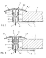
- the cross-sectional representation of a preferred embodiment of the joint bridging arrangement according to the invention is preferably used for bridging of joints in a parquet floor 1, the parquet floor 1 for simplicity only on one side the fugue is shown.
- Joint bridging arrangement on a base profile 2 the by a screw 3 shown only schematically on the Floor is screwed.
- the basic profile 2 is essentially L-shaped and has two legs 4.1 and 4.2 on that from the base plate of the base profile 2 so protrude at right angles into the joint, whereby the two legs 4.1 and 4.2 in the longitudinal direction in extend substantially over the entire length of the joint.
- joint bridging arrangement according to the invention 1, a cover profile 5 with two cover wings 6.1 and 6.2, with the two cover wings 6.1 and 6.2 rest on both sides of the joint on the parquet floor 1.
- an intermediate part 7 is arranged, the Scope regarding the height adjustability of the joint bridging arrangement compared to those described at the beginning known joint bridging arrangements expanded. So points the intermediate part 7 on its underside two legs 8.1 and 8.2 on, the two legs in the assembled state 4.1 and 4.2 of the base profile 2 reach around the outside and thereby a lateral guide of the intermediate part 2 relative to effect the basic profile 2. In addition, the intermediate part on its top two legs 9.1 and 9.2 on that on the outside of two at the bottom of the Cover profile 5 arranged legs 10.1 and 10.2 encompassed so that the leg pairs 9.1, 10.1 or 9.2, 10.2 a side guide of the cover profile 5 relative to effect the intermediate part 7.
- the fastening of the cover profile 5 and the intermediate part 7 on the base profile 2 is carried out by a screw 11 through appropriate holes in the cover profile 5 and Intermediate part 7 is introduced.
- the scope for height adjustability is further expanded be vertical by several intermediate parts 7 stacked on top of each other. That of the two legs 8.1 and 8.2 of the intermediate part included clear width therefore essentially equal to the outside width of the two Legs 9.1 and 9.2 of the intermediate part 7 to make them stackable to ensure.
- a major difference from that shown in Figure 2 Joint bridging arrangement compared to that shown in Figure 1 Joint bridging arrangement is that the Attachment of the cover profile 5 to the intermediate part 7 is not by a screw connection, but by locking. In this embodiment, this is on the underside of the cover profile 5 a leg 12 is formed, the also has a detent on both sides, the in the assembled state in the locking of the legs 9.1 and 9.2 of the intermediate part engages.
- the intermediate part 7 For fastening the intermediate part 7 to the base profile 2 has the intermediate part 7 in this embodiment on it Bottom of a single leg 13 on the Lateral surfaces along the joint a detent is attached.
- the two upstanding legs 4.1, 4.2 of the base profile 2 wear on the inside along the Add a notch in which the notch of the leg 13 engages, and the intermediate part 7 thus vertical fixed.
- the joint bridging arrangement according to Figure 3 enables advantageous assembly without tools, since the attachment only by locking.
- the intermediate part 7 points accordingly two legs 15.1 and 15.2 arranged side by side, while at the top of the base plate of the base profile 2 a leg 16 projecting upward at right angles is formed is that in the assembled state of the two legs 15.1 and 15.2 of the intermediate part 7 is gripped laterally and thereby a lateral guide of the intermediate part 7 relative to the base profile 2.
- the on the inside of the legs 15.1, 15.2 and on the outside of the leg 16 arranged detents a vertical Fixing the intermediate part 7 relative to the base profile Second
- cover profile 5 is attached to the Base profile 2 also with a screw connection.
- the peculiarity of the embodiment shown in Figure 6 is that for the connection of the cover profile 5 with the intermediate part 7 and for fastening the A separate part 7 on the base profile 2 Screw 18, 19 is provided.
- the base profile 2 is first replaced by a only schematically illustrated screw 3 on the floor screwed.
- the intermediate part 7 is on the base profile 2 placed that the two legs projecting downwards 8.1, 8.2 of the intermediate part 7, the two projecting upwards Grip legs 4.1, 4.2 of base profile 2 laterally.
- the screw 19 is then replaced by a screw in the intermediate part 7 centrally arranged bore passed through the two legs 4.1, 4.2 of the base profile 2 have a threaded bore (The tapped hole can also be through a threaded drive channel be formed) for the screw 19.
- the screw 19 is then corresponding to that to be bridged Height difference and the thickness of the floor covering 1 attracted.
- the screw 19 can only be slightly tightened, so that the legs 4.1, 4.2 of the base profile 2 are not on the intermediate part 7, just a side guide cause. With a thin floor covering 1 Screw 19, however, may be tightened so far that the legs 4.1, 4.2 of the base profile 2 at the top of the intermediate part Strike 7.
- the cover profile 5 will be like this placed on the intermediate part 7 that the legs 10.1, 10.2 of the cover profile 5, the legs 9.1, 9.2 of the intermediate part 7 reach around the side.
- the second screw 18 by a mounted in the cover profile 5 Countersunk hole inserted, with the upstanding Legs 9.1, 9.2 of the intermediate part 7 a threaded bore (The tapped hole can also be through a threaded drive channel be formed) for the second screw 18.
- the Screw 18 is then tightened until the cover wing 6.2 of the cover profile 5 with the desired tension lies on the floor covering.
Landscapes
- Architecture (AREA)
- Engineering & Computer Science (AREA)
- Civil Engineering (AREA)
- Structural Engineering (AREA)
- Floor Finish (AREA)
- Superconductors And Manufacturing Methods Therefor (AREA)
- Paper (AREA)
- Ceramic Products (AREA)
- Control Of Motors That Do Not Use Commutators (AREA)
- Non-Disconnectible Joints And Screw-Threaded Joints (AREA)
- Seal Device For Vehicle (AREA)
- Manufacturing Of Electrical Connectors (AREA)
- Joints Allowing Movement (AREA)
Claims (16)
- Agencement de couvre-joint pour un plancher, et notamment en vue de couvrir un joint dans un parquet présentant des différences de niveaux des bords de joints se faisant face, avec
un profil de base (2) permettant la fixation au plancher à l'aide d'au moins une partie latérale (4,1, 4,2) avançant vers le haut dans le joint,
un profil de recouvrement (5) permettant de couvrir le joint avec au moins une partie latérale (10,1, 10,2, 12) avançant vers le haut dans le joint, ainsi
qu'un élément de fixation (11, 17) permettant une fixation du profil de recouvrement (5) réglable en hauteur au niveau du profil de base (2),
caractérisé en ce qu'au moins une pièce intermédiaire (7) est agencée entre le profil de base (2) et le profil de recouvrement (5), pour étendre la possibilité de réglage en hauteur, la pièce intermédiaire (7) étant fixée au niveau de sa face inférieure au profil de base (2) et au niveau de sa surface supérieure au profil de recouvrement (5). - Agencement de couvre-joint selon la revendication 1, caractérisé en ce que la pièce intermédiaire (7) est superposable afin de permettre l'extension de la possibilité de réglage en hauteur par la mise en place de plusieurs pièces intermédiaires (7).
- Agencement de couvre-joint selon la revendication 1 ou 2, caractérisé en ce que le profil de base (2) présente deux parties latérales (-4,1, 4,2) s'avançant vers le haut dans le joint et agencées l'un à côté de l'autre.
- Agencement de couvre-joint selon la revendication 3, caractérisé en ce que la pièce intermédiaire (7) présente au moins une partie latérale (13) au niveau de sa face inférieure, laquelle partie est, à l'état monté, encadrée de façon latérale par les deux parties latérales (4,1, 4,2) du profil de base (2) .
- Agencement de couvre-joint selon la revendication 3 ou 4, caractérisé en ce que la pièce intermédiaire (7) présente au moins deux parties latérales (9,1, 9,2) au niveau de sa face supérieure, lesquelles parties encadrent, à l'état monté, de façon latérale la partie latérale (12) du profil de recouvrement (5).
- Agencement de couvre-joint selon la revendication 1 ou 2, caractérisé en ce que le profil de recouvrement (5) présente deux parties latérales agencées l'une à côté de l'autre (10,1, 10,2), lesquelles parties s'avancent vers le bas dans le joint.
- Agencement de couvre-joint selon la revendication 6, caractérisé en ce que la pièce intermédiaire (7) présente au moins au niveau de sa face supérieure une partie latérale (14), qui est, à l'état monté, encadrée, de façon latérale par les parties latérales (10,1, 10,2) du profil de recouvrement.
- Agencement de couvre-joint selon la revendication 7, caractérisé en ce qu'un canal fileté est agencé dans la partie latérale (14) agencée au niveau de la face supérieure de la pièce intermédiaire (7), en vue de fixer le profil de recouvrement (5) par l'intermédiaire d'une vis (17) au niveau de la pièce intermédiaire (7).
- Agencement de couvre-joint selon la revendication 7 ou 8, caractérisé en ce que la pièce intermédiaire (7) présente au moins deux parties latérales (15,1, 15,2) au niveau de sa face inférieure, lesquelles parties encadrent de façon latérale à l'état monté, la partie latérale (16) du profil de base (2).
- Agencement de couvre-joint selon la revendication 9, caractérisé en ce qu'un canal fileté est agencé dans l'une des parties latérales du profil de base (2), en vue de fixer la pièce intermédiaire (7) au profil de base (2) par l'intermédiaire d'une vis.
- Agencement de couvre-joint selon l'une quelconque des revendications précédentes, caractérisé en ce que les parties latérales adjacentes du profil de base (2) et de la pièce intermédiaire (7) présentent des crans d'arrêt au niveau des surfaces de contact, en vue de fixer la pièce intermédiaire (7) au profil de base (2).
- Agencement de couvre-joint selon l'une quelconque des revendications précédentes, caractérisé en ce que les parties latérales adjacentes du profil de recouvrement (5) et de la pièce intermédiaire (7) présentent des crans d'arrêt au niveau des surfaces de contact, en vue de fixer le profil de recouvrement (5) à la pièce intermédiaire (7).
- Agencement selon au moins l'une quelconque des revendications précédentes, caractérisé en ce que la pièce intermédiaire (7) présente au niveau de sa face supérieure un canal fileté, en vue de visser le profil de recouvrement (5) avec la pièce intermédiaire (7).
- Agencement de couvre-joint selon la revendication 13, caractérisé en ce que le canal fileté est formé par deux parties latérales (9,1, 9,2) de la pièce intermédiaire (7) se dressant vers le haut.
- Agencement selon au moins l'une quelconque des revendications précédentes, caractérisé en ce que le profil de bas (2) présente au niveau de sa face supérieure un canal fileté, en vue de visser la pièce intermédiaire (7) avec le profil de base (2).
- Agencement de couvre-joint selon la revendication 15, caractérisé en ce que le canal fileté est formé par deux parties latérales (4,1, 4,2) du profil de base (2) se dressant vers le haut.
Applications Claiming Priority (3)
| Application Number | Priority Date | Filing Date | Title |
|---|---|---|---|
| DE19951516A DE19951516C2 (de) | 1999-10-26 | 1999-10-26 | Fugenüberbrückungsanordnung |
| DE19951516 | 1999-10-26 | ||
| PCT/EP2000/010512 WO2001031141A1 (fr) | 1999-10-26 | 2000-10-25 | Dispositif de passage de jonction |
Publications (4)
| Publication Number | Publication Date |
|---|---|
| EP1224366A1 EP1224366A1 (fr) | 2002-07-24 |
| EP1224366B1 true EP1224366B1 (fr) | 2003-08-27 |
| EP1224366B2 EP1224366B2 (fr) | 2010-06-30 |
| EP1224366B9 EP1224366B9 (fr) | 2012-08-08 |
Family
ID=7926904
Family Applications (1)
| Application Number | Title | Priority Date | Filing Date |
|---|---|---|---|
| EP00975913A Expired - Lifetime EP1224366B9 (fr) | 1999-10-26 | 2000-10-25 | Dispositif de passage de jonction |
Country Status (7)
| Country | Link |
|---|---|
| EP (1) | EP1224366B9 (fr) |
| AT (1) | ATE248271T1 (fr) |
| DE (2) | DE19951516C2 (fr) |
| DK (1) | DK1224366T4 (fr) |
| ES (1) | ES2207558T5 (fr) |
| PT (1) | PT1224366E (fr) |
| WO (1) | WO2001031141A1 (fr) |
Families Citing this family (28)
| Publication number | Priority date | Publication date | Assignee | Title |
|---|---|---|---|---|
| SE503861C2 (sv) | 1994-10-24 | 1996-09-23 | Perstorp Flooring Ab | Förfarande för framställning av en golvlist |
| US20030084634A1 (en) | 2001-11-08 | 2003-05-08 | Oliver Stanchfield | Transition molding |
| US6898911B2 (en) | 1997-04-25 | 2005-05-31 | Pergo (Europe) Ab | Floor strip |
| US7131242B2 (en) | 1995-03-07 | 2006-11-07 | Pergo (Europe) Ab | Flooring panel or wall panel and use thereof |
| SE9500810D0 (sv) | 1995-03-07 | 1995-03-07 | Perstorp Flooring Ab | Golvplatta |
| US7992358B2 (en) | 1998-02-04 | 2011-08-09 | Pergo AG | Guiding means at a joint |
| SE514645C2 (sv) | 1998-10-06 | 2001-03-26 | Perstorp Flooring Ab | Golvbeläggningsmaterial innefattande skivformiga golvelement avsedda att sammanfogas av separata sammanfogningsprofiler |
| SE518184C2 (sv) | 2000-03-31 | 2002-09-03 | Perstorp Flooring Ab | Golvbeläggningsmaterial innefattande skivformiga golvelement vilka sammanfogas med hjälp av sammankopplingsorgan |
| FR2815983B1 (fr) * | 2000-11-02 | 2003-06-06 | Michel Grosjean | Couvre-joint |
| SG111031A1 (en) * | 2001-10-01 | 2005-05-30 | L & K Engineering Co Ltd | Honeycomb plate structure with joining assembly |
| US7207143B2 (en) | 2001-11-08 | 2007-04-24 | Pergo (Europe) Ab | Transition molding and installation methods therefor |
| DE10322633B3 (de) * | 2003-05-20 | 2004-11-25 | Müller, Werner | Schienenanordnung zum Abdecken oder Überbrücken von Fugen, insbesondere für Fußböden |
| DE20309990U1 (de) | 2003-06-29 | 2003-09-04 | Fiedler, Karl-Heinz, 56281 Emmelshausen | Fußbodenleiste |
| DE10349932A1 (de) * | 2003-10-24 | 2005-05-25 | Herm. Friedr. Künne Gmbh & Co. | Fußbodenprofilanordnung |
| DE202004000726U1 (de) * | 2004-01-17 | 2004-04-15 | Fiedler, Karl-Heinz | Fußbodenleiste |
| GB2422104B (en) * | 2004-12-08 | 2008-08-13 | Whiting Richard A | An engaging assembly for a floor covering |
| GB0519531D0 (en) * | 2005-09-24 | 2005-11-02 | Whiting Richard A | Engaging assembly for flooring |
| DE202006004903U1 (de) * | 2006-03-24 | 2006-06-01 | Herm. Friedr. Künne Gmbh & Co. | Abdeckanordnung mit Magnetsystem |
| WO2008048655A2 (fr) | 2006-10-18 | 2008-04-24 | Pfleiderer Schweiz Ag | Joints ayant des surfaces disparates |
| GB0626007D0 (en) * | 2006-12-29 | 2007-02-07 | Whiting Richard A | Engaging assembly for a floor covering |
| DE202007000716U1 (de) | 2007-01-17 | 2007-03-29 | Fiedler, Karl-Heinz | Profilschiene |
| DE112007003385A5 (de) * | 2007-03-26 | 2010-04-29 | Proverum Ag | Profilleistensystem für einen Belag, insbesondere zum Randabschluss und/oder zur Fugenabdeckung und/oder für einen Kabelkanal |
| CA2697573A1 (fr) | 2009-03-27 | 2010-09-27 | Pergo (Europe) Ab | Ensemble de recouvrement de joints, trousse comprenant cet ensemble et procede d'installation connexe |
| DE102010004717A1 (de) | 2010-01-15 | 2011-07-21 | Pergo (Europe) Ab | Set aus Paneelen umfassend Halteprofile mit einem separaten Clip sowie Verfahren zum Einbringen des Clips |
| CN104831904B (zh) | 2010-05-10 | 2017-05-24 | 佩尔戈(欧洲)股份公司 | 地板组件 |
| DE102012107007A1 (de) * | 2012-07-31 | 2014-02-06 | Küberit Profile Systems GmbH & Co. KG | Kippbare Fußbodenprofilanordnung |
| DE102016014441A1 (de) | 2016-12-06 | 2018-06-07 | Markus Claudius Proll | Adapter für Fugenabdeckvorrichtung |
| DE102016014442A1 (de) | 2016-12-06 | 2018-06-07 | Markus Claudius Proll | Adapter für Fugenabdeckvorrichtung |
Family Cites Families (9)
| Publication number | Priority date | Publication date | Assignee | Title |
|---|---|---|---|---|
| FR2456246B1 (fr) † | 1979-05-08 | 1985-11-08 | Bobath Peter | Dispositif pour joindre bord a bord des panneaux |
| DE3634729A1 (de) * | 1986-10-31 | 1987-05-27 | Manfred Neu | Bauelement zum befestigen von glasscheiben |
| DE3743895A1 (de) * | 1987-12-23 | 1989-07-13 | Herm Friedr Kuenne Fa | Abnehmbares ueberbrueckungsprofil fuer fussbodenfugen |
| DE4136177A1 (de) * | 1991-11-02 | 1993-05-06 | Helmuth J. 8074 Gaimersheim De Seiss | Profilleisten-bausatz |
| DE9116524U1 (de) * | 1991-12-17 | 1992-12-17 | Schlüter Systems GmbH, 5860 Iserlohn | Kastenförmiges Profil aus Kunststoff zur Ausbildung von Entspannungsfugen in mit Keramikplatten belegten Böden oder Wänden |
| DE9301717U1 (de) * | 1993-02-08 | 1993-04-08 | Seiß, Helmut, 8074 Gaimersheim | Schienenbausatz |
| DE9412987U1 (de) * | 1994-08-11 | 1994-10-27 | Seiß, Helmut, 85080 Gaimersheim | Profilschienensystem zum Überbrücken von Fugen oder Rändern bei Belägen |
| DE29611649U1 (de) * | 1996-07-04 | 1996-09-12 | Seiß, Helmuth J., 85080 Gaimersheim | Vorrichtung zum Festlegen einer Abdeckschiene für eine Treppenstufe |
| IT1308118B1 (it) † | 1999-01-15 | 2001-11-29 | Daniele Fontana | Elemento di raccordo per pavimenti. |
-
1999
- 1999-10-26 DE DE19951516A patent/DE19951516C2/de not_active Expired - Fee Related
-
2000
- 2000-10-25 PT PT00975913T patent/PT1224366E/pt unknown
- 2000-10-25 DE DE50003473T patent/DE50003473D1/de not_active Expired - Lifetime
- 2000-10-25 AT AT00975913T patent/ATE248271T1/de active
- 2000-10-25 EP EP00975913A patent/EP1224366B9/fr not_active Expired - Lifetime
- 2000-10-25 WO PCT/EP2000/010512 patent/WO2001031141A1/fr not_active Ceased
- 2000-10-25 DK DK00975913.5T patent/DK1224366T4/da active
- 2000-10-25 ES ES00975913T patent/ES2207558T5/es not_active Expired - Lifetime
Also Published As
| Publication number | Publication date |
|---|---|
| WO2001031141A1 (fr) | 2001-05-03 |
| EP1224366B9 (fr) | 2012-08-08 |
| ATE248271T1 (de) | 2003-09-15 |
| EP1224366A1 (fr) | 2002-07-24 |
| DE19951516C2 (de) | 2003-04-24 |
| DE19951516A1 (de) | 2001-06-07 |
| ES2207558T5 (es) | 2010-11-25 |
| EP1224366B2 (fr) | 2010-06-30 |
| PT1224366E (pt) | 2004-01-30 |
| ES2207558T3 (es) | 2004-06-01 |
| DK1224366T3 (da) | 2003-12-29 |
| DK1224366T4 (da) | 2010-11-01 |
| DE50003473D1 (de) | 2003-10-02 |
Similar Documents
| Publication | Publication Date | Title |
|---|---|---|
| EP1224366B1 (fr) | Dispositif de passage de jonction | |
| EP2050898B1 (fr) | Agencement de profilés de sol articulés | |
| EP0007397A1 (fr) | Ferrure | |
| DE4032427B4 (de) | Verbindungsvorrichtung für ein Wischblatt, insbesondere an einem Kraftfahrzeug | |
| DE2610200A1 (de) | Beschlag zum loesbaren verbinden von bauteilen, insbesondere zum wieder loesbaren verbinden von plattenfoermigen bauteilen | |
| EP2848159A1 (fr) | Poignée | |
| EP3565979A1 (fr) | Système de fixation et boîtier d'armoire de commande correspondant | |
| DE69919189T2 (de) | Spielzeugbausatz | |
| EP0369326A2 (fr) | Dispositif isolant de liaison pour panneaux de construction | |
| DE102017125877A1 (de) | Verankerungsbeschlag zur Verankerung in einem Werkstück | |
| AT403500B (de) | Beschlagteileverbindung | |
| DE2852829A1 (de) | Schnellmontagesockel aus kunststoff | |
| DE2744052A1 (de) | Beschlag fuer tueren und waende aus glas | |
| EP0818591B1 (fr) | Elément de montage | |
| DE69410982T2 (de) | Stellbare Vorrichtung, insbesondere für Metallrahmen | |
| DE202005019612U1 (de) | Vorrichtung zur lösbaren Befestigung eines flachen Bauteils an einer Trägerstruktur | |
| DE20117167U1 (de) | Fußbodenprofilanordnung | |
| DE29924459U1 (de) | Fugenüberbrückungsanordnung | |
| EP1744420A1 (fr) | Armoire, notamment armoire de commutation ou de distribution | |
| EP0079541A1 (fr) | Dispositif muni d'un cadre profilé | |
| EP0867626A1 (fr) | Moyens de liaison pour le premontage d'une vis | |
| DE4039421A1 (de) | Klemmverbindung | |
| DE7121021U (de) | Treibstangenbeschlag | |
| DE2649149A1 (de) | Anschlag fuer in einer schiene einer gardinenleiste laufende befestigungselemente | |
| DE2035560C (de) | Plattenförmiges Bauelement |
Legal Events
| Date | Code | Title | Description |
|---|---|---|---|
| PUAI | Public reference made under article 153(3) epc to a published international application that has entered the european phase |
Free format text: ORIGINAL CODE: 0009012 |
|
| 17P | Request for examination filed |
Effective date: 20020515 |
|
| AK | Designated contracting states |
Kind code of ref document: A1 Designated state(s): AT BE CH CY DE DK ES FI FR GB GR IE IT LI LU MC NL PT SE |
|
| GRAH | Despatch of communication of intention to grant a patent |
Free format text: ORIGINAL CODE: EPIDOS IGRA |
|
| GRAS | Grant fee paid |
Free format text: ORIGINAL CODE: EPIDOSNIGR3 |
|
| GRAA | (expected) grant |
Free format text: ORIGINAL CODE: 0009210 |
|
| AK | Designated contracting states |
Designated state(s): AT BE CH CY DE DK ES FI FR GB GR IE IT LI LU MC NL PT SE |
|
| PG25 | Lapsed in a contracting state [announced via postgrant information from national office to epo] |
Ref country code: FI Free format text: LAPSE BECAUSE OF FAILURE TO SUBMIT A TRANSLATION OF THE DESCRIPTION OR TO PAY THE FEE WITHIN THE PRESCRIBED TIME-LIMIT Effective date: 20030827 Ref country code: IE Free format text: LAPSE BECAUSE OF FAILURE TO SUBMIT A TRANSLATION OF THE DESCRIPTION OR TO PAY THE FEE WITHIN THE PRESCRIBED TIME-LIMIT Effective date: 20030827 |
|
| REG | Reference to a national code |
Ref country code: GB Ref legal event code: FG4D Free format text: NOT ENGLISH |
|
| REG | Reference to a national code |
Ref country code: CH Ref legal event code: EP |
|
| REG | Reference to a national code |
Ref country code: IE Ref legal event code: FG4D Free format text: GERMAN |
|
| REF | Corresponds to: |
Ref document number: 50003473 Country of ref document: DE Date of ref document: 20031002 Kind code of ref document: P |
|
| PG25 | Lapsed in a contracting state [announced via postgrant information from national office to epo] |
Ref country code: LU Free format text: LAPSE BECAUSE OF NON-PAYMENT OF DUE FEES Effective date: 20031025 Ref country code: CY Free format text: LAPSE BECAUSE OF FAILURE TO SUBMIT A TRANSLATION OF THE DESCRIPTION OR TO PAY THE FEE WITHIN THE PRESCRIBED TIME-LIMIT Effective date: 20031025 |
|
| PG25 | Lapsed in a contracting state [announced via postgrant information from national office to epo] |
Ref country code: MC Free format text: LAPSE BECAUSE OF NON-PAYMENT OF DUE FEES Effective date: 20031031 |
|
| PG25 | Lapsed in a contracting state [announced via postgrant information from national office to epo] |
Ref country code: GR Free format text: LAPSE BECAUSE OF FAILURE TO SUBMIT A TRANSLATION OF THE DESCRIPTION OR TO PAY THE FEE WITHIN THE PRESCRIBED TIME-LIMIT Effective date: 20031127 |
|
| REG | Reference to a national code |
Ref country code: SE Ref legal event code: TRGR |
|
| REG | Reference to a national code |
Ref country code: DK Ref legal event code: T3 |
|
| GBT | Gb: translation of ep patent filed (gb section 77(6)(a)/1977) |
Effective date: 20031222 |
|
| REG | Reference to a national code |
Ref country code: CH Ref legal event code: NV Representative=s name: BOVARD AG PATENTANWAELTE |
|
| REG | Reference to a national code |
Ref country code: IE Ref legal event code: FD4D |
|
| PLBQ | Unpublished change to opponent data |
Free format text: ORIGINAL CODE: EPIDOS OPPO |
|
| REG | Reference to a national code |
Ref country code: ES Ref legal event code: FG2A Ref document number: 2207558 Country of ref document: ES Kind code of ref document: T3 |
|
| PLBI | Opposition filed |
Free format text: ORIGINAL CODE: 0009260 |
|
| PLAX | Notice of opposition and request to file observation + time limit sent |
Free format text: ORIGINAL CODE: EPIDOSNOBS2 |
|
| ET | Fr: translation filed | ||
| 26 | Opposition filed |
Opponent name: XAVER GRUENWALD Effective date: 20040526 |
|
| NLR1 | Nl: opposition has been filed with the epo |
Opponent name: XAVER GRUENWALD |
|
| PLAX | Notice of opposition and request to file observation + time limit sent |
Free format text: ORIGINAL CODE: EPIDOSNOBS2 |
|
| PLBB | Reply of patent proprietor to notice(s) of opposition received |
Free format text: ORIGINAL CODE: EPIDOSNOBS3 |
|
| PLAY | Examination report in opposition despatched + time limit |
Free format text: ORIGINAL CODE: EPIDOSNORE2 |
|
| PLAH | Information related to despatch of examination report in opposition + time limit modified |
Free format text: ORIGINAL CODE: EPIDOSCORE2 |
|
| PLBC | Reply to examination report in opposition received |
Free format text: ORIGINAL CODE: EPIDOSNORE3 |
|
| PUAH | Patent maintained in amended form |
Free format text: ORIGINAL CODE: 0009272 |
|
| STAA | Information on the status of an ep patent application or granted ep patent |
Free format text: STATUS: PATENT MAINTAINED AS AMENDED |
|
| 27A | Patent maintained in amended form |
Effective date: 20100630 |
|
| AK | Designated contracting states |
Kind code of ref document: B2 Designated state(s): AT BE CH CY DE DK ES FI FR GB GR IE IT LI LU MC NL PT SE |
|
| REG | Reference to a national code |
Ref country code: CH Ref legal event code: AEN Free format text: AUFRECHTERHALTUNG DES PATENTES IN GEAENDERTER FORM |
|
| REG | Reference to a national code |
Ref country code: NL Ref legal event code: T3 |
|
| REG | Reference to a national code |
Ref country code: SE Ref legal event code: RPEO |
|
| REG | Reference to a national code |
Ref country code: DK Ref legal event code: T4 |
|
| REG | Reference to a national code |
Ref country code: CH Ref legal event code: PFA Owner name: HERM. FRIEDR. KUENNE GMBH & CO. Free format text: HERM. FRIEDR. KUENNE GMBH & CO.#ROEMERWEG 9#58513 LUEDENSCHEID (DE) -TRANSFER TO- HERM. FRIEDR. KUENNE GMBH & CO.#ROEMERWEG 9#58513 LUEDENSCHEID (DE) |
|
| REG | Reference to a national code |
Ref country code: DE Ref legal event code: R082 Ref document number: 50003473 Country of ref document: DE Representative=s name: PATENTANWAELTE STAEGER & SPERLING PARTNERSCHAF, DE |
|
| REG | Reference to a national code |
Ref country code: DE Ref legal event code: R082 Ref document number: 50003473 Country of ref document: DE Representative=s name: PATENTANWAELTE STAEGER & SPERLING PARTNERSCHAF, DE Effective date: 20120319 Ref country code: DE Ref legal event code: R081 Ref document number: 50003473 Country of ref document: DE Owner name: KUEBERIT PROFILE SYSTEMS GMBH & CO. KG, DE Free format text: FORMER OWNER: SONDERMANN, FRANK, 57489 DROLSHAGEN, DE Effective date: 20120319 |
|
| REG | Reference to a national code |
Ref country code: FR Ref legal event code: PLFP Year of fee payment: 16 |
|
| PGFP | Annual fee paid to national office [announced via postgrant information from national office to epo] |
Ref country code: DK Payment date: 20151021 Year of fee payment: 16 |
|
| PGFP | Annual fee paid to national office [announced via postgrant information from national office to epo] |
Ref country code: GB Payment date: 20151021 Year of fee payment: 16 Ref country code: IT Payment date: 20151028 Year of fee payment: 16 |
|
| PGFP | Annual fee paid to national office [announced via postgrant information from national office to epo] |
Ref country code: PT Payment date: 20151020 Year of fee payment: 16 Ref country code: SE Payment date: 20151021 Year of fee payment: 16 Ref country code: FR Payment date: 20151023 Year of fee payment: 16 Ref country code: BE Payment date: 20151019 Year of fee payment: 16 Ref country code: ES Payment date: 20151028 Year of fee payment: 16 |
|
| PG25 | Lapsed in a contracting state [announced via postgrant information from national office to epo] |
Ref country code: BE Free format text: LAPSE BECAUSE OF NON-PAYMENT OF DUE FEES Effective date: 20161031 |
|
| REG | Reference to a national code |
Ref country code: DK Ref legal event code: EBP Effective date: 20161031 |
|
| GBPC | Gb: european patent ceased through non-payment of renewal fee |
Effective date: 20161025 |
|
| REG | Reference to a national code |
Ref country code: FR Ref legal event code: ST Effective date: 20170630 |
|
| PG25 | Lapsed in a contracting state [announced via postgrant information from national office to epo] |
Ref country code: GB Free format text: LAPSE BECAUSE OF NON-PAYMENT OF DUE FEES Effective date: 20161025 Ref country code: FR Free format text: LAPSE BECAUSE OF NON-PAYMENT OF DUE FEES Effective date: 20161102 |
|
| PG25 | Lapsed in a contracting state [announced via postgrant information from national office to epo] |
Ref country code: PT Free format text: LAPSE BECAUSE OF NON-PAYMENT OF DUE FEES Effective date: 20170426 Ref country code: SE Free format text: LAPSE BECAUSE OF NON-PAYMENT OF DUE FEES Effective date: 20161026 |
|
| PG25 | Lapsed in a contracting state [announced via postgrant information from national office to epo] |
Ref country code: IT Free format text: LAPSE BECAUSE OF NON-PAYMENT OF DUE FEES Effective date: 20161025 |
|
| PG25 | Lapsed in a contracting state [announced via postgrant information from national office to epo] |
Ref country code: DK Free format text: LAPSE BECAUSE OF NON-PAYMENT OF DUE FEES Effective date: 20161031 |
|
| REG | Reference to a national code |
Ref country code: BE Ref legal event code: MM Effective date: 20161031 |
|
| PG25 | Lapsed in a contracting state [announced via postgrant information from national office to epo] |
Ref country code: ES Free format text: LAPSE BECAUSE OF FAILURE TO SUBMIT A TRANSLATION OF THE DESCRIPTION OR TO PAY THE FEE WITHIN THE PRESCRIBED TIME-LIMIT Effective date: 20030827 |
|
| REG | Reference to a national code |
Ref country code: ES Ref legal event code: FD2A Effective date: 20181119 |
|
| PGFP | Annual fee paid to national office [announced via postgrant information from national office to epo] |
Ref country code: NL Payment date: 20181019 Year of fee payment: 19 |
|
| PGFP | Annual fee paid to national office [announced via postgrant information from national office to epo] |
Ref country code: AT Payment date: 20181022 Year of fee payment: 19 |
|
| PG25 | Lapsed in a contracting state [announced via postgrant information from national office to epo] |
Ref country code: ES Free format text: LAPSE BECAUSE OF FAILURE TO SUBMIT A TRANSLATION OF THE DESCRIPTION OR TO PAY THE FEE WITHIN THE PRESCRIBED TIME-LIMIT Effective date: 20161026 |
|
| PGFP | Annual fee paid to national office [announced via postgrant information from national office to epo] |
Ref country code: CH Payment date: 20181019 Year of fee payment: 19 |
|
| PGFP | Annual fee paid to national office [announced via postgrant information from national office to epo] |
Ref country code: DE Payment date: 20181220 Year of fee payment: 19 |
|
| REG | Reference to a national code |
Ref country code: DE Ref legal event code: R119 Ref document number: 50003473 Country of ref document: DE |
|
| REG | Reference to a national code |
Ref country code: CH Ref legal event code: PL |
|
| REG | Reference to a national code |
Ref country code: NL Ref legal event code: MM Effective date: 20191101 |
|
| PG25 | Lapsed in a contracting state [announced via postgrant information from national office to epo] |
Ref country code: DE Free format text: LAPSE BECAUSE OF NON-PAYMENT OF DUE FEES Effective date: 20200501 Ref country code: LI Free format text: LAPSE BECAUSE OF NON-PAYMENT OF DUE FEES Effective date: 20191031 Ref country code: CH Free format text: LAPSE BECAUSE OF NON-PAYMENT OF DUE FEES Effective date: 20191031 |
|
| REG | Reference to a national code |
Ref country code: AT Ref legal event code: MM01 Ref document number: 248271 Country of ref document: AT Kind code of ref document: T Effective date: 20191025 |
|
| PG25 | Lapsed in a contracting state [announced via postgrant information from national office to epo] |
Ref country code: NL Free format text: LAPSE BECAUSE OF NON-PAYMENT OF DUE FEES Effective date: 20191101 |
|
| PG25 | Lapsed in a contracting state [announced via postgrant information from national office to epo] |
Ref country code: AT Free format text: LAPSE BECAUSE OF NON-PAYMENT OF DUE FEES Effective date: 20191025 |