EP1224366B9 - Dispositif de passage de jonction - Google Patents
Dispositif de passage de jonction Download PDFInfo
- Publication number
- EP1224366B9 EP1224366B9 EP00975913A EP00975913A EP1224366B9 EP 1224366 B9 EP1224366 B9 EP 1224366B9 EP 00975913 A EP00975913 A EP 00975913A EP 00975913 A EP00975913 A EP 00975913A EP 1224366 B9 EP1224366 B9 EP 1224366B9
- Authority
- EP
- European Patent Office
- Prior art keywords
- joint
- profile
- leg
- legs
- base profile
- Prior art date
- Legal status (The legal status is an assumption and is not a legal conclusion. Google has not performed a legal analysis and makes no representation as to the accuracy of the status listed.)
- Expired - Lifetime
Links
- 238000011161 development Methods 0.000 description 1
- 230000018109 developmental process Effects 0.000 description 1
- 238000009434 installation Methods 0.000 description 1
Images

Classifications
-
- E—FIXED CONSTRUCTIONS
- E04—BUILDING
- E04F—FINISHING WORK ON BUILDINGS, e.g. STAIRS, FLOORS
- E04F19/00—Other details of constructional parts for finishing work on buildings
- E04F19/02—Borders; Finishing strips, e.g. beadings; Light coves
- E04F19/06—Borders; Finishing strips, e.g. beadings; Light coves specially designed for securing panels or masking the edges of wall- or floor-covering elements
- E04F19/065—Finishing profiles with a T-shaped cross-section or the like
- E04F19/067—Finishing profiles with a T-shaped cross-section or the like with means preventing a tipping movement
-
- E—FIXED CONSTRUCTIONS
- E04—BUILDING
- E04F—FINISHING WORK ON BUILDINGS, e.g. STAIRS, FLOORS
- E04F19/00—Other details of constructional parts for finishing work on buildings
- E04F19/02—Borders; Finishing strips, e.g. beadings; Light coves
- E04F19/06—Borders; Finishing strips, e.g. beadings; Light coves specially designed for securing panels or masking the edges of wall- or floor-covering elements
- E04F19/062—Borders; Finishing strips, e.g. beadings; Light coves specially designed for securing panels or masking the edges of wall- or floor-covering elements used between similar elements
-
- E—FIXED CONSTRUCTIONS
- E04—BUILDING
- E04F—FINISHING WORK ON BUILDINGS, e.g. STAIRS, FLOORS
- E04F19/00—Other details of constructional parts for finishing work on buildings
- E04F19/02—Borders; Finishing strips, e.g. beadings; Light coves
- E04F19/06—Borders; Finishing strips, e.g. beadings; Light coves specially designed for securing panels or masking the edges of wall- or floor-covering elements
- E04F19/065—Finishing profiles with a T-shaped cross-section or the like
- E04F19/066—Finishing profiles with a T-shaped cross-section or the like fixed onto a base profile by means of a separate connector
Definitions
- the invention relates to a Fugenüberb Wegungsan extract for a floor, in particular for bridging a joint in a parquet floor with different heights of the opposite joint edges according to the preamble of claims 1, 2 and 3.
- Such a joint bridging arrangement which consists of an L-shaped base profile and a covering profile attached to the base profile.
- the base profile is in this case fastened by a screw on the floor, wherein the one leg of the L-shaped base profile protrudes upward into the joint.
- the cover profile covers the joint and has two downwardly projecting into the joint leg, which laterally engage around the legs of the L-shaped profile and thereby cause a lateral guidance of the cover.
- the attachment of the cover profile to the base profile is effected by a screw which is screwed through a hole in the cover in a threaded drive channel, which is arranged in the upwardly projecting into the joint leg of the base profile.
- a disadvantage of the above-described known joint bridging arrangement is the fact that in terms of height adjustment of the joint bridging arrangement, there is only a relatively small margin, since the two legs of the cover must include the upwardly projecting leg of the base profile laterally to ensure lateral guidance.
- EPC EP 1020590 A2 a joint bridging arrangement is known in which an intermediate part is fixed to a cover profile neither via a latching nor via a screw connection.
- the invention is therefore an object of the invention to provide a joint bridging arrangement of the type described above, which has an expanded scope in terms of height adjustment.
- the invention includes the general technical teaching not to attach the cover directly to the base profile, but to arrange an intermediate part between the base profile and the cover.
- the intermediate part is in this case stackable, so that the margin in terms of height adjustment by inserting any number of intermediate parts can be extended almost arbitrarily.
- the intermediate part has on its underside two legs arranged next to one another, which laterally engage around the upwardly projecting leg of the base profile.
- the intermediate part preferably has a leg on the upper side, which is laterally encompassed by two legs arranged on the underside of the covering profile in order to ensure lateral guidance.
- the attachment of the cover profile to the intermediate part or the attachment of the intermediate part to the base profile can be done in various ways.
- the cover profile is screwed to the intermediate part, wherein in the upwardly projecting leg of the intermediate part a threaded drive channel is provided as a socket for the screw.
- a threaded drive channel is provided as a socket for the screw.
- the attachment of the cover profile on the intermediate part can be effected by a latching.
- the present invention is not limited in its application to floor joints, but can generally be used for bridging joints, with the joint bridging arrangement according to the invention is particularly advantageous for bridging joints in parquet floors.
- the joint bridging arrangement has a base profile 2 which is screwed tightly to the floor by means of a screw 3, which is shown only schematically.
- the base profile 2 is formed substantially L-shaped and has two legs 4.1 and 4.2, which protrude from the base plate of the base profile 2 at right angles up into the joint, with the two legs 4.1 and 4.2 in the longitudinal direction substantially over the extend the entire length of the joint.
- the joint bridging arrangement according to FIG. 1 a cover profile 5 with two covering wings 6.1 and 6.2, wherein the two covering wings 6.1 and 6.2 rest on both sides of the joint on the parquet floor 1.
- an intermediate part 7 is arranged, which expands the scope in terms of height adjustment of the joint bridging arrangement with respect to the known Fugenüberbrückungsan extract described above.
- the intermediate part 7 on its underside two legs 8.1 and 8.2 the two legs 4.1 and 4.2 of the base profile 2 engage around the outside in the mounted state laterally and thereby cause a side guide of the intermediate part 2 relative to the base profile 2.
- the intermediate part on its upper side two legs 9.1 and 9.2 which are embraced on its outside by two arranged on the underside of the cover 5 legs 10.1 and 10.2, so that the leg pairs 9.1, 10.1 and 9.2, 10.2 a side guide Cover profile 5 relative to the intermediate part 7 effect.
- the attachment of the cover 5 and the intermediate part 7 to the base profile 2 is effected by a screw 11 which is inserted through corresponding holes in the cover 5 and the intermediate part 7.
- the margin for height adjustability can be further extended by stacking a plurality of intermediate pieces 7 vertically one above the other.
- the width covered by the two legs 8.1 and 8.2 of the intermediate part is therefore substantially equal to the outer width of the two legs 9.1 and 9.2 of the intermediate part 7 in order to ensure stackability.
- FIG. 2 illustrated embodiment of a joint bridging arrangement is largely consistent with that described above and in FIG. 1 illustrated embodiment, so that the following reference numerals are used in the following for matching components and reference is made in this regard to avoid repetition of the above description.
- FIG. 2 illustrated joint bridging arrangement compared to in FIG. 1 Joints bridging arrangement shown is that the attachment of the cover 5 on the intermediate part 7 is not done by a screw, but by a latching.
- a leg 12 is integrally formed in this embodiment on the underside of the cover 5, which also has a detent on its two side surfaces, which engages in the mounted state in the detent of the legs 9.1 and 9.2 of the intermediate part.
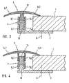
- FIG. 3 reproduced embodiment of the invention also largely coincides with the embodiments described above, so that in the following also the same reference numerals are used and reference is made to avoid repetition of the above description.
- FIG. 3 illustrated embodiment with respect to the embodiments described above is essentially that the attachment of the cover 5, the intermediate part 7 and the base profile 2 to each other exclusively by locking.
- the attachment of the cover 5 on the intermediate part 7 takes place here in the same manner as in FIG. 2 so in that regard Reference is made to the above description.
- the intermediate part 7 For attachment of the intermediate part 7 to the base profile 2, the intermediate part 7 in this embodiment on its underside a single leg 13, on the side surfaces along the joint a detent is attached.
- the two upwardly projecting legs 4.1, 4.2 of the base profile 2 in this case also carry on their inside along the joint a detent into which engages the detent of the leg 13, and the intermediate part 7 thus fixed vertically.
- the joint bridging arrangement according to FIG. 3 advantageously allows installation without tools, since the attachment is made exclusively by locking.
- FIG. 4 illustrated embodiment of a joint bridging arrangement according to the invention is almost complete with the in FIG. 3 reproduced embodiment, so that reference is largely made to the above description.
- FIG. 4 illustrated embodiment consists essentially in that the arrangement of the legs is geometrically reversed.
- the cover 5 has on its underside the two legs 10.1 and 10.2, whose inner sides bear detents.
- a leg 14 is integrally formed, which is laterally encompassed in the mounted state of the two legs 10.1 and 10.2 of the cover 5 and also carries notches, so that the cover 5 is fixed by the latching vertical to the intermediate part 7 ,
- the intermediate part 7 On its underside, the intermediate part 7 corresponding to two juxtaposed legs 15.1 and 15.2, while at the top of the base plate of the base profile 2, a right-angled upwardly projecting leg 16 is formed in the mounted state of the two legs 15.1 and 15.2 of the intermediate part. 7 is laterally encompassed and thereby causes a lateral guidance of the intermediate part 7 relative to the base profile 2. In addition, cause the arranged on the inside of the legs 15.1, 15.2 and on the outside of the leg 16 notches a vertical fixation of the intermediate part 7 relative to the base profile. 2
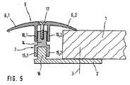
- FIG. 5 illustrated embodiment of the joint bridging arrangement according to the invention in turn largely agrees with the in FIG. 4 illustrated embodiment, so that reference is largely made to the above description.
- FIG. 5 illustrated embodiment An essential difference of in FIG. 5 illustrated embodiment with respect to in FIG. 4 illustrated embodiment is that the attachment of the cover 5 on the intermediate part 7 is not done by a catch, but by a screw.
- a threaded drive channel is arranged in the upwardly projecting leg 14 of the intermediate part 7, in which a screw 17 engages, which is inserted through a hole in the top of the cover.
Landscapes
- Architecture (AREA)
- Engineering & Computer Science (AREA)
- Civil Engineering (AREA)
- Structural Engineering (AREA)
- Floor Finish (AREA)
- Superconductors And Manufacturing Methods Therefor (AREA)
- Paper (AREA)
- Ceramic Products (AREA)
- Control Of Motors That Do Not Use Commutators (AREA)
- Non-Disconnectible Joints And Screw-Threaded Joints (AREA)
- Seal Device For Vehicle (AREA)
- Manufacturing Of Electrical Connectors (AREA)
- Joints Allowing Movement (AREA)
Claims (4)
- Dispositif de franchissement de joint pour un sol, en particulier pour le franchissement d'un joint dans un sol de parquet avec différentes hauteurs des bords de joint opposés, avec un profil de base (2) pour la fixation au sol avec au moins une branche (4.1, 4.2) s'engageant vers le haut dans le joint,
un profilé de recouvrement (5) pour recouvrir le joint avec une branche (12) s'engageant dans le joint vers le bas ainsi
qu'un élément de fixation pour la fixation réglable en hauteur du profil de recouvrement (5) sur le profilé de base (2),
caractérisé en ce
qu'entre le profilé de base (2) et le profil de recouvrement (5), il est disposé au moins une pièce intermédiaire (7) pour agrandir le réglage en hauteur, la pièce intermédiaire (7) étant fixée sur sa face inférieure au profil de base (2) et sur sa face supérieure sur le profilé de recouvrement (5),
le profilé de base (2) présentant deux branches (4.1, 4.2) disposées l'une à côté de l'autre et s'engageant vers le haut dans le joint,
la pièce intermédiaire (7) présentant sur sa face inférieure une branche (13) qui est entourée latéralement à l'état monté par les deux branches (4.1, 4.2) du profilé de base (2),
la pièce intermédiaire (7) présentant sur sa face supérieure deux branches (9.1, 9.2) qui entourent latéralement à l'état monté la branche (12) du profilé de recouvrement (5),
les branches appliquées l'une contre l'autre du profilé de base (2) et de la pièce Intermédiaire (7) présentant sur les surfaces de contact des encoches d'encliquetage pour fixer le profilé de base (2) sur la pièce intermédiaire (7),
les branches appliquées l'une contre l'autre du profilé de recouvrement (5) et de la pièce intermédiaire (7) présentant sur les surfaces de contact des encoches d'encliquetage pour fixer le profilé de recouvrement (5) sur la pièce intermédiaire (7). - Dispositif de franchissement de joint pour un sol, en particulier pour le franchissement d'un joint dans un sol de parquet avec différentes hauteurs des bords de joints opposés, avec un profilé de base (2) pour la fixation au sol avec une branche (16) s'engageant vers le haut dans le joint,
un profilé de recouvrement (5) pour recouvrir le joint avec au moins une branche (12) s'engageant dans le joint vers le bas ainsi
qu'un élément de fixation pour la fixation réglable en hauteur du profil de recouvrement (5) sur le profil de base (2),
caractérisé en ce
qu'entre le profilé de base (2) et le profilé de recouvrement (5), il est disposé au moins une pièce intermédiaire (7) pour agrandir le réglage en hauteur, la pièce intermédiaire (7) étant fixée sur sa face inférieure au profilé de base (2) et sur sa face supérieure au profilé de recouvrement (5),
le profilé de recouvrement (5) présentant deux branches (10.1, 10.2) disposées l'une à côté de l'autre qui s'engagent dans le joint vers le bas,
la pièce intermédiaire (7) présentant sur sa face supérieure une branche (14) qui est entourée latéralement à l'état monté par les branches (10.1, 10,2) du profilé de recouvrement (5),
la pièce intermédiaire (7) présentant sur sa face inférieure deux branches (15.1, 15.2) qui entourent latéralement à l'état monté la branche (16) du profilé de base (2),
les branches appliquées l'une contre l'autre du profilé de base (2) et de la pièce intermédiaire (7) présentant sur les surfaces de contact des encoches d'encliquetage pour fixer le la pièce intermédiaire (7) sur le profilé de base (2),
les branches appliquées l'une contre l'autre du profilé de recouvrement (5) et de la pièce intermédiaire (7) présentant sur les surfaces de contact des encoches d'encliquetage pour fixer le profilé de recouvrement (5) sur la pièce intermédiaire (7). - Dispositif de franchissement de joint pour un sol, en particulier pour le franchissement d'un joint dans un sol de parquet avec différentes hauteurs des bords de joint opposés, avec un profilé de base (2) pour la fixation au sol avec au moins une branche (4.1, 4.2) s'engageant vers le haut dans le joint,
un profilé de recouvrement (5) pour recouvrir le joint avec au moins une branche (10.1, 10.2) s'engageant dans le joint vers le bas ainsi
qu'un élément de fixation (17) pour la fixation réglable en hauteur du profilé de recouvrement (5) sur le profilé de base (2),
caractérisé en ce
qu'entre le profilé de base (2) et le profilé de recouvrement (5), il est disposé au moins une pièce intermédiaire (7) pour agrandir le réglage en hauteur, la pièce intermédiaire (7) étant fixée sur sa face inférieure au profilé de base (2) et sur sa face supérieure sur le profilé de recouvrement (5),
le profilé de recouvrement (5) présentant deux branches (10.1, 10.2) disposées l'une à côté de l'autre qui s'engagent dans le joint vers le bas,
la pièce intermédiaire (7) présentant sur sa face supérieure une branche (14) qui est entourée latéralement à l'état monté par les branches (10.1, 10.2) du profilé de recouvrement (5),
dans la branche (14) disposée sur la face supérieure de la pièce intermédiaire (7), un canal de filetage étant disposé pour fixer le profilé de recouvrement (5) par une vis (17) sur la partie intermédiaire (7). - Dispositif de franchissement de joint selon l'une des revendications 1, 2 ou 3, caractérisé en ce que la partie intermédiaire (7) est empilable pour pouvoir agrandir le réglage en hauteur en utilisant plusieurs pièces intermédiaires (7).
Applications Claiming Priority (3)
| Application Number | Priority Date | Filing Date | Title |
|---|---|---|---|
| DE19951516A DE19951516C2 (de) | 1999-10-26 | 1999-10-26 | Fugenüberbrückungsanordnung |
| DE19951516 | 1999-10-26 | ||
| PCT/EP2000/010512 WO2001031141A1 (fr) | 1999-10-26 | 2000-10-25 | Dispositif de passage de jonction |
Publications (4)
| Publication Number | Publication Date |
|---|---|
| EP1224366A1 EP1224366A1 (fr) | 2002-07-24 |
| EP1224366B1 EP1224366B1 (fr) | 2003-08-27 |
| EP1224366B2 EP1224366B2 (fr) | 2010-06-30 |
| EP1224366B9 true EP1224366B9 (fr) | 2012-08-08 |
Family
ID=7926904
Family Applications (1)
| Application Number | Title | Priority Date | Filing Date |
|---|---|---|---|
| EP00975913A Expired - Lifetime EP1224366B9 (fr) | 1999-10-26 | 2000-10-25 | Dispositif de passage de jonction |
Country Status (7)
| Country | Link |
|---|---|
| EP (1) | EP1224366B9 (fr) |
| AT (1) | ATE248271T1 (fr) |
| DE (2) | DE19951516C2 (fr) |
| DK (1) | DK1224366T4 (fr) |
| ES (1) | ES2207558T5 (fr) |
| PT (1) | PT1224366E (fr) |
| WO (1) | WO2001031141A1 (fr) |
Families Citing this family (28)
| Publication number | Priority date | Publication date | Assignee | Title |
|---|---|---|---|---|
| SE503861C2 (sv) | 1994-10-24 | 1996-09-23 | Perstorp Flooring Ab | Förfarande för framställning av en golvlist |
| US20030084634A1 (en) | 2001-11-08 | 2003-05-08 | Oliver Stanchfield | Transition molding |
| US6898911B2 (en) | 1997-04-25 | 2005-05-31 | Pergo (Europe) Ab | Floor strip |
| US7131242B2 (en) | 1995-03-07 | 2006-11-07 | Pergo (Europe) Ab | Flooring panel or wall panel and use thereof |
| SE9500810D0 (sv) | 1995-03-07 | 1995-03-07 | Perstorp Flooring Ab | Golvplatta |
| US7992358B2 (en) | 1998-02-04 | 2011-08-09 | Pergo AG | Guiding means at a joint |
| SE514645C2 (sv) | 1998-10-06 | 2001-03-26 | Perstorp Flooring Ab | Golvbeläggningsmaterial innefattande skivformiga golvelement avsedda att sammanfogas av separata sammanfogningsprofiler |
| SE518184C2 (sv) | 2000-03-31 | 2002-09-03 | Perstorp Flooring Ab | Golvbeläggningsmaterial innefattande skivformiga golvelement vilka sammanfogas med hjälp av sammankopplingsorgan |
| FR2815983B1 (fr) * | 2000-11-02 | 2003-06-06 | Michel Grosjean | Couvre-joint |
| SG111031A1 (en) * | 2001-10-01 | 2005-05-30 | L & K Engineering Co Ltd | Honeycomb plate structure with joining assembly |
| US7207143B2 (en) | 2001-11-08 | 2007-04-24 | Pergo (Europe) Ab | Transition molding and installation methods therefor |
| DE10322633B3 (de) * | 2003-05-20 | 2004-11-25 | Müller, Werner | Schienenanordnung zum Abdecken oder Überbrücken von Fugen, insbesondere für Fußböden |
| DE20309990U1 (de) | 2003-06-29 | 2003-09-04 | Fiedler, Karl-Heinz, 56281 Emmelshausen | Fußbodenleiste |
| DE10349932A1 (de) * | 2003-10-24 | 2005-05-25 | Herm. Friedr. Künne Gmbh & Co. | Fußbodenprofilanordnung |
| DE202004000726U1 (de) * | 2004-01-17 | 2004-04-15 | Fiedler, Karl-Heinz | Fußbodenleiste |
| GB2422104B (en) * | 2004-12-08 | 2008-08-13 | Whiting Richard A | An engaging assembly for a floor covering |
| GB0519531D0 (en) * | 2005-09-24 | 2005-11-02 | Whiting Richard A | Engaging assembly for flooring |
| DE202006004903U1 (de) * | 2006-03-24 | 2006-06-01 | Herm. Friedr. Künne Gmbh & Co. | Abdeckanordnung mit Magnetsystem |
| WO2008048655A2 (fr) | 2006-10-18 | 2008-04-24 | Pfleiderer Schweiz Ag | Joints ayant des surfaces disparates |
| GB0626007D0 (en) * | 2006-12-29 | 2007-02-07 | Whiting Richard A | Engaging assembly for a floor covering |
| DE202007000716U1 (de) | 2007-01-17 | 2007-03-29 | Fiedler, Karl-Heinz | Profilschiene |
| DE112007003385A5 (de) * | 2007-03-26 | 2010-04-29 | Proverum Ag | Profilleistensystem für einen Belag, insbesondere zum Randabschluss und/oder zur Fugenabdeckung und/oder für einen Kabelkanal |
| CA2697573A1 (fr) | 2009-03-27 | 2010-09-27 | Pergo (Europe) Ab | Ensemble de recouvrement de joints, trousse comprenant cet ensemble et procede d'installation connexe |
| DE102010004717A1 (de) | 2010-01-15 | 2011-07-21 | Pergo (Europe) Ab | Set aus Paneelen umfassend Halteprofile mit einem separaten Clip sowie Verfahren zum Einbringen des Clips |
| CN104831904B (zh) | 2010-05-10 | 2017-05-24 | 佩尔戈(欧洲)股份公司 | 地板组件 |
| DE102012107007A1 (de) * | 2012-07-31 | 2014-02-06 | Küberit Profile Systems GmbH & Co. KG | Kippbare Fußbodenprofilanordnung |
| DE102016014441A1 (de) | 2016-12-06 | 2018-06-07 | Markus Claudius Proll | Adapter für Fugenabdeckvorrichtung |
| DE102016014442A1 (de) | 2016-12-06 | 2018-06-07 | Markus Claudius Proll | Adapter für Fugenabdeckvorrichtung |
Family Cites Families (9)
| Publication number | Priority date | Publication date | Assignee | Title |
|---|---|---|---|---|
| FR2456246B1 (fr) † | 1979-05-08 | 1985-11-08 | Bobath Peter | Dispositif pour joindre bord a bord des panneaux |
| DE3634729A1 (de) * | 1986-10-31 | 1987-05-27 | Manfred Neu | Bauelement zum befestigen von glasscheiben |
| DE3743895A1 (de) * | 1987-12-23 | 1989-07-13 | Herm Friedr Kuenne Fa | Abnehmbares ueberbrueckungsprofil fuer fussbodenfugen |
| DE4136177A1 (de) * | 1991-11-02 | 1993-05-06 | Helmuth J. 8074 Gaimersheim De Seiss | Profilleisten-bausatz |
| DE9116524U1 (de) * | 1991-12-17 | 1992-12-17 | Schlüter Systems GmbH, 5860 Iserlohn | Kastenförmiges Profil aus Kunststoff zur Ausbildung von Entspannungsfugen in mit Keramikplatten belegten Böden oder Wänden |
| DE9301717U1 (de) * | 1993-02-08 | 1993-04-08 | Seiß, Helmut, 8074 Gaimersheim | Schienenbausatz |
| DE9412987U1 (de) * | 1994-08-11 | 1994-10-27 | Seiß, Helmut, 85080 Gaimersheim | Profilschienensystem zum Überbrücken von Fugen oder Rändern bei Belägen |
| DE29611649U1 (de) * | 1996-07-04 | 1996-09-12 | Seiß, Helmuth J., 85080 Gaimersheim | Vorrichtung zum Festlegen einer Abdeckschiene für eine Treppenstufe |
| IT1308118B1 (it) † | 1999-01-15 | 2001-11-29 | Daniele Fontana | Elemento di raccordo per pavimenti. |
-
1999
- 1999-10-26 DE DE19951516A patent/DE19951516C2/de not_active Expired - Fee Related
-
2000
- 2000-10-25 PT PT00975913T patent/PT1224366E/pt unknown
- 2000-10-25 DE DE50003473T patent/DE50003473D1/de not_active Expired - Lifetime
- 2000-10-25 AT AT00975913T patent/ATE248271T1/de active
- 2000-10-25 EP EP00975913A patent/EP1224366B9/fr not_active Expired - Lifetime
- 2000-10-25 WO PCT/EP2000/010512 patent/WO2001031141A1/fr not_active Ceased
- 2000-10-25 DK DK00975913.5T patent/DK1224366T4/da active
- 2000-10-25 ES ES00975913T patent/ES2207558T5/es not_active Expired - Lifetime
Also Published As
| Publication number | Publication date |
|---|---|
| WO2001031141A1 (fr) | 2001-05-03 |
| EP1224366B1 (fr) | 2003-08-27 |
| ATE248271T1 (de) | 2003-09-15 |
| EP1224366A1 (fr) | 2002-07-24 |
| DE19951516C2 (de) | 2003-04-24 |
| DE19951516A1 (de) | 2001-06-07 |
| ES2207558T5 (es) | 2010-11-25 |
| EP1224366B2 (fr) | 2010-06-30 |
| PT1224366E (pt) | 2004-01-30 |
| ES2207558T3 (es) | 2004-06-01 |
| DK1224366T3 (da) | 2003-12-29 |
| DK1224366T4 (da) | 2010-11-01 |
| DE50003473D1 (de) | 2003-10-02 |
Similar Documents
| Publication | Publication Date | Title |
|---|---|---|
| EP1224366B9 (fr) | Dispositif de passage de jonction | |
| DE2501099A1 (de) | Befestigungsklammer | |
| DE3132855C2 (fr) | ||
| EP0007397A1 (fr) | Ferrure | |
| EP0399955B1 (fr) | Elément de fermeture pour verrouiller un couvercle dans un cadre | |
| DE29610026U1 (de) | Steck-Kupplung | |
| EP0067970B1 (fr) | Dispositif de fixation pour éléments de façade | |
| DE19707741C2 (de) | Möbelscharnier | |
| EP0818591B1 (fr) | Elément de montage | |
| EP3369341B1 (fr) | Élément mural pour un châssis d'un tiroir | |
| DE19747887C2 (de) | Halteelement | |
| DE29603235U1 (de) | Wannenträger | |
| DE102020114795B4 (de) | Befestigungselement | |
| DE20117167U1 (de) | Fußbodenprofilanordnung | |
| DE20000662U1 (de) | Konstruktionssystem für Gestelle, Möbel o.dgl. | |
| DE2744052A1 (de) | Beschlag fuer tueren und waende aus glas | |
| DE29924459U1 (de) | Fugenüberbrückungsanordnung | |
| DE69810240T2 (de) | Verfahren zur Herstellung eines Möbelfusses oder dergleichen | |
| DE19846577C2 (de) | Elektrisches Gerät mit einem Verbindungsclip und einer Verbindungsclipaufnahme zur Verbindung mit einem zweiten elektrischen Gerät | |
| EP0867626B1 (fr) | Moyens de liaison pour le premontage d'une vis | |
| DE3613655C1 (de) | In Moebel,Waende od.dgl. einsetzbare Rastschiene und Verfahren zum Einsetzen einer solchen Rastschiene | |
| DE3641163C2 (fr) | ||
| DE20022356U1 (de) | Installationskanal mit Verbindungsvorrichtung | |
| DE19540540C2 (de) | Verbindung von Leiterplatte und Steckverbinder und damit versehene Steckkarte für elektronische Geräte | |
| DE19745073A1 (de) | Verbindungselement für Möbelsysteme |
Legal Events
| Date | Code | Title | Description |
|---|---|---|---|
| PUAI | Public reference made under article 153(3) epc to a published international application that has entered the european phase |
Free format text: ORIGINAL CODE: 0009012 |
|
| 17P | Request for examination filed |
Effective date: 20020515 |
|
| AK | Designated contracting states |
Kind code of ref document: A1 Designated state(s): AT BE CH CY DE DK ES FI FR GB GR IE IT LI LU MC NL PT SE |
|
| GRAH | Despatch of communication of intention to grant a patent |
Free format text: ORIGINAL CODE: EPIDOS IGRA |
|
| GRAS | Grant fee paid |
Free format text: ORIGINAL CODE: EPIDOSNIGR3 |
|
| GRAA | (expected) grant |
Free format text: ORIGINAL CODE: 0009210 |
|
| AK | Designated contracting states |
Designated state(s): AT BE CH CY DE DK ES FI FR GB GR IE IT LI LU MC NL PT SE |
|
| PG25 | Lapsed in a contracting state [announced via postgrant information from national office to epo] |
Ref country code: FI Free format text: LAPSE BECAUSE OF FAILURE TO SUBMIT A TRANSLATION OF THE DESCRIPTION OR TO PAY THE FEE WITHIN THE PRESCRIBED TIME-LIMIT Effective date: 20030827 Ref country code: IE Free format text: LAPSE BECAUSE OF FAILURE TO SUBMIT A TRANSLATION OF THE DESCRIPTION OR TO PAY THE FEE WITHIN THE PRESCRIBED TIME-LIMIT Effective date: 20030827 |
|
| REG | Reference to a national code |
Ref country code: GB Ref legal event code: FG4D Free format text: NOT ENGLISH |
|
| REG | Reference to a national code |
Ref country code: CH Ref legal event code: EP |
|
| REG | Reference to a national code |
Ref country code: IE Ref legal event code: FG4D Free format text: GERMAN |
|
| REF | Corresponds to: |
Ref document number: 50003473 Country of ref document: DE Date of ref document: 20031002 Kind code of ref document: P |
|
| PG25 | Lapsed in a contracting state [announced via postgrant information from national office to epo] |
Ref country code: LU Free format text: LAPSE BECAUSE OF NON-PAYMENT OF DUE FEES Effective date: 20031025 Ref country code: CY Free format text: LAPSE BECAUSE OF FAILURE TO SUBMIT A TRANSLATION OF THE DESCRIPTION OR TO PAY THE FEE WITHIN THE PRESCRIBED TIME-LIMIT Effective date: 20031025 |
|
| PG25 | Lapsed in a contracting state [announced via postgrant information from national office to epo] |
Ref country code: MC Free format text: LAPSE BECAUSE OF NON-PAYMENT OF DUE FEES Effective date: 20031031 |
|
| PG25 | Lapsed in a contracting state [announced via postgrant information from national office to epo] |
Ref country code: GR Free format text: LAPSE BECAUSE OF FAILURE TO SUBMIT A TRANSLATION OF THE DESCRIPTION OR TO PAY THE FEE WITHIN THE PRESCRIBED TIME-LIMIT Effective date: 20031127 |
|
| REG | Reference to a national code |
Ref country code: SE Ref legal event code: TRGR |
|
| REG | Reference to a national code |
Ref country code: DK Ref legal event code: T3 |
|
| GBT | Gb: translation of ep patent filed (gb section 77(6)(a)/1977) |
Effective date: 20031222 |
|
| REG | Reference to a national code |
Ref country code: CH Ref legal event code: NV Representative=s name: BOVARD AG PATENTANWAELTE |
|
| REG | Reference to a national code |
Ref country code: IE Ref legal event code: FD4D |
|
| PLBQ | Unpublished change to opponent data |
Free format text: ORIGINAL CODE: EPIDOS OPPO |
|
| REG | Reference to a national code |
Ref country code: ES Ref legal event code: FG2A Ref document number: 2207558 Country of ref document: ES Kind code of ref document: T3 |
|
| PLBI | Opposition filed |
Free format text: ORIGINAL CODE: 0009260 |
|
| PLAX | Notice of opposition and request to file observation + time limit sent |
Free format text: ORIGINAL CODE: EPIDOSNOBS2 |
|
| ET | Fr: translation filed | ||
| 26 | Opposition filed |
Opponent name: XAVER GRUENWALD Effective date: 20040526 |
|
| NLR1 | Nl: opposition has been filed with the epo |
Opponent name: XAVER GRUENWALD |
|
| PLAX | Notice of opposition and request to file observation + time limit sent |
Free format text: ORIGINAL CODE: EPIDOSNOBS2 |
|
| PLBB | Reply of patent proprietor to notice(s) of opposition received |
Free format text: ORIGINAL CODE: EPIDOSNOBS3 |
|
| PLAY | Examination report in opposition despatched + time limit |
Free format text: ORIGINAL CODE: EPIDOSNORE2 |
|
| PLAH | Information related to despatch of examination report in opposition + time limit modified |
Free format text: ORIGINAL CODE: EPIDOSCORE2 |
|
| PLBC | Reply to examination report in opposition received |
Free format text: ORIGINAL CODE: EPIDOSNORE3 |
|
| PUAH | Patent maintained in amended form |
Free format text: ORIGINAL CODE: 0009272 |
|
| STAA | Information on the status of an ep patent application or granted ep patent |
Free format text: STATUS: PATENT MAINTAINED AS AMENDED |
|
| 27A | Patent maintained in amended form |
Effective date: 20100630 |
|
| AK | Designated contracting states |
Kind code of ref document: B2 Designated state(s): AT BE CH CY DE DK ES FI FR GB GR IE IT LI LU MC NL PT SE |
|
| REG | Reference to a national code |
Ref country code: CH Ref legal event code: AEN Free format text: AUFRECHTERHALTUNG DES PATENTES IN GEAENDERTER FORM |
|
| REG | Reference to a national code |
Ref country code: NL Ref legal event code: T3 |
|
| REG | Reference to a national code |
Ref country code: SE Ref legal event code: RPEO |
|
| REG | Reference to a national code |
Ref country code: DK Ref legal event code: T4 |
|
| REG | Reference to a national code |
Ref country code: CH Ref legal event code: PFA Owner name: HERM. FRIEDR. KUENNE GMBH & CO. Free format text: HERM. FRIEDR. KUENNE GMBH & CO.#ROEMERWEG 9#58513 LUEDENSCHEID (DE) -TRANSFER TO- HERM. FRIEDR. KUENNE GMBH & CO.#ROEMERWEG 9#58513 LUEDENSCHEID (DE) |
|
| REG | Reference to a national code |
Ref country code: DE Ref legal event code: R082 Ref document number: 50003473 Country of ref document: DE Representative=s name: PATENTANWAELTE STAEGER & SPERLING PARTNERSCHAF, DE |
|
| REG | Reference to a national code |
Ref country code: DE Ref legal event code: R082 Ref document number: 50003473 Country of ref document: DE Representative=s name: PATENTANWAELTE STAEGER & SPERLING PARTNERSCHAF, DE Effective date: 20120319 Ref country code: DE Ref legal event code: R081 Ref document number: 50003473 Country of ref document: DE Owner name: KUEBERIT PROFILE SYSTEMS GMBH & CO. KG, DE Free format text: FORMER OWNER: SONDERMANN, FRANK, 57489 DROLSHAGEN, DE Effective date: 20120319 |
|
| REG | Reference to a national code |
Ref country code: FR Ref legal event code: PLFP Year of fee payment: 16 |
|
| PGFP | Annual fee paid to national office [announced via postgrant information from national office to epo] |
Ref country code: DK Payment date: 20151021 Year of fee payment: 16 |
|
| PGFP | Annual fee paid to national office [announced via postgrant information from national office to epo] |
Ref country code: GB Payment date: 20151021 Year of fee payment: 16 Ref country code: IT Payment date: 20151028 Year of fee payment: 16 |
|
| PGFP | Annual fee paid to national office [announced via postgrant information from national office to epo] |
Ref country code: PT Payment date: 20151020 Year of fee payment: 16 Ref country code: SE Payment date: 20151021 Year of fee payment: 16 Ref country code: FR Payment date: 20151023 Year of fee payment: 16 Ref country code: BE Payment date: 20151019 Year of fee payment: 16 Ref country code: ES Payment date: 20151028 Year of fee payment: 16 |
|
| PG25 | Lapsed in a contracting state [announced via postgrant information from national office to epo] |
Ref country code: BE Free format text: LAPSE BECAUSE OF NON-PAYMENT OF DUE FEES Effective date: 20161031 |
|
| REG | Reference to a national code |
Ref country code: DK Ref legal event code: EBP Effective date: 20161031 |
|
| GBPC | Gb: european patent ceased through non-payment of renewal fee |
Effective date: 20161025 |
|
| REG | Reference to a national code |
Ref country code: FR Ref legal event code: ST Effective date: 20170630 |
|
| PG25 | Lapsed in a contracting state [announced via postgrant information from national office to epo] |
Ref country code: GB Free format text: LAPSE BECAUSE OF NON-PAYMENT OF DUE FEES Effective date: 20161025 Ref country code: FR Free format text: LAPSE BECAUSE OF NON-PAYMENT OF DUE FEES Effective date: 20161102 |
|
| PG25 | Lapsed in a contracting state [announced via postgrant information from national office to epo] |
Ref country code: PT Free format text: LAPSE BECAUSE OF NON-PAYMENT OF DUE FEES Effective date: 20170426 Ref country code: SE Free format text: LAPSE BECAUSE OF NON-PAYMENT OF DUE FEES Effective date: 20161026 |
|
| PG25 | Lapsed in a contracting state [announced via postgrant information from national office to epo] |
Ref country code: IT Free format text: LAPSE BECAUSE OF NON-PAYMENT OF DUE FEES Effective date: 20161025 |
|
| PG25 | Lapsed in a contracting state [announced via postgrant information from national office to epo] |
Ref country code: DK Free format text: LAPSE BECAUSE OF NON-PAYMENT OF DUE FEES Effective date: 20161031 |
|
| REG | Reference to a national code |
Ref country code: BE Ref legal event code: MM Effective date: 20161031 |
|
| PG25 | Lapsed in a contracting state [announced via postgrant information from national office to epo] |
Ref country code: ES Free format text: LAPSE BECAUSE OF FAILURE TO SUBMIT A TRANSLATION OF THE DESCRIPTION OR TO PAY THE FEE WITHIN THE PRESCRIBED TIME-LIMIT Effective date: 20030827 |
|
| REG | Reference to a national code |
Ref country code: ES Ref legal event code: FD2A Effective date: 20181119 |
|
| PGFP | Annual fee paid to national office [announced via postgrant information from national office to epo] |
Ref country code: NL Payment date: 20181019 Year of fee payment: 19 |
|
| PGFP | Annual fee paid to national office [announced via postgrant information from national office to epo] |
Ref country code: AT Payment date: 20181022 Year of fee payment: 19 |
|
| PG25 | Lapsed in a contracting state [announced via postgrant information from national office to epo] |
Ref country code: ES Free format text: LAPSE BECAUSE OF FAILURE TO SUBMIT A TRANSLATION OF THE DESCRIPTION OR TO PAY THE FEE WITHIN THE PRESCRIBED TIME-LIMIT Effective date: 20161026 |
|
| PGFP | Annual fee paid to national office [announced via postgrant information from national office to epo] |
Ref country code: CH Payment date: 20181019 Year of fee payment: 19 |
|
| PGFP | Annual fee paid to national office [announced via postgrant information from national office to epo] |
Ref country code: DE Payment date: 20181220 Year of fee payment: 19 |
|
| REG | Reference to a national code |
Ref country code: DE Ref legal event code: R119 Ref document number: 50003473 Country of ref document: DE |
|
| REG | Reference to a national code |
Ref country code: CH Ref legal event code: PL |
|
| REG | Reference to a national code |
Ref country code: NL Ref legal event code: MM Effective date: 20191101 |
|
| PG25 | Lapsed in a contracting state [announced via postgrant information from national office to epo] |
Ref country code: DE Free format text: LAPSE BECAUSE OF NON-PAYMENT OF DUE FEES Effective date: 20200501 Ref country code: LI Free format text: LAPSE BECAUSE OF NON-PAYMENT OF DUE FEES Effective date: 20191031 Ref country code: CH Free format text: LAPSE BECAUSE OF NON-PAYMENT OF DUE FEES Effective date: 20191031 |
|
| REG | Reference to a national code |
Ref country code: AT Ref legal event code: MM01 Ref document number: 248271 Country of ref document: AT Kind code of ref document: T Effective date: 20191025 |
|
| PG25 | Lapsed in a contracting state [announced via postgrant information from national office to epo] |
Ref country code: NL Free format text: LAPSE BECAUSE OF NON-PAYMENT OF DUE FEES Effective date: 20191101 |
|
| PG25 | Lapsed in a contracting state [announced via postgrant information from national office to epo] |
Ref country code: AT Free format text: LAPSE BECAUSE OF NON-PAYMENT OF DUE FEES Effective date: 20191025 |