EP1224996A2 - Verfahren zum Kühlen von Widerstandspunktschweissanlagen, insbesondere wassergekühlten Punktschweisszangen, und Einrichtung zur Durchführung des Verfahrens - Google Patents
Verfahren zum Kühlen von Widerstandspunktschweissanlagen, insbesondere wassergekühlten Punktschweisszangen, und Einrichtung zur Durchführung des Verfahrens Download PDFInfo
- Publication number
- EP1224996A2 EP1224996A2 EP02000443A EP02000443A EP1224996A2 EP 1224996 A2 EP1224996 A2 EP 1224996A2 EP 02000443 A EP02000443 A EP 02000443A EP 02000443 A EP02000443 A EP 02000443A EP 1224996 A2 EP1224996 A2 EP 1224996A2
- Authority
- EP
- European Patent Office
- Prior art keywords
- cooling water
- welding
- cooling
- supply line
- water supply
- Prior art date
- Legal status (The legal status is an assumption and is not a legal conclusion. Google has not performed a legal analysis and makes no representation as to the accuracy of the status listed.)
- Granted
Links
- 238000003466 welding Methods 0.000 title claims abstract description 84
- 238000001816 cooling Methods 0.000 title claims abstract description 31
- 238000000034 method Methods 0.000 title claims abstract description 26
- XLYOFNOQVPJJNP-UHFFFAOYSA-N water Substances O XLYOFNOQVPJJNP-UHFFFAOYSA-N 0.000 title claims description 6
- 239000000498 cooling water Substances 0.000 claims abstract description 108
- 239000002826 coolant Substances 0.000 claims abstract description 4
- 230000001276 controlling effect Effects 0.000 claims 1
- 230000001419 dependent effect Effects 0.000 claims 1
- 230000001105 regulatory effect Effects 0.000 claims 1
- 230000002996 emotional effect Effects 0.000 abstract 1
- 238000005192 partition Methods 0.000 description 3
- 238000010586 diagram Methods 0.000 description 2
- 238000005086 pumping Methods 0.000 description 2
- 230000004888 barrier function Effects 0.000 description 1
- FFBHFFJDDLITSX-UHFFFAOYSA-N benzyl N-[2-hydroxy-4-(3-oxomorpholin-4-yl)phenyl]carbamate Chemical compound OC1=C(NC(=O)OCC2=CC=CC=C2)C=CC(=C1)N1CCOCC1=O FFBHFFJDDLITSX-UHFFFAOYSA-N 0.000 description 1
- 230000000903 blocking effect Effects 0.000 description 1
- 238000010276 construction Methods 0.000 description 1
- 238000011161 development Methods 0.000 description 1
- 230000018109 developmental process Effects 0.000 description 1
- 230000000694 effects Effects 0.000 description 1
- 238000010438 heat treatment Methods 0.000 description 1
- 238000005259 measurement Methods 0.000 description 1
Images

Classifications
-
- B—PERFORMING OPERATIONS; TRANSPORTING
- B23—MACHINE TOOLS; METAL-WORKING NOT OTHERWISE PROVIDED FOR
- B23K—SOLDERING OR UNSOLDERING; WELDING; CLADDING OR PLATING BY SOLDERING OR WELDING; CUTTING BY APPLYING HEAT LOCALLY, e.g. FLAME CUTTING; WORKING BY LASER BEAM
- B23K11/00—Resistance welding; Severing by resistance heating
- B23K11/30—Features relating to electrodes
- B23K11/3054—Cooled electrodes
Definitions
- the invention relates to a method for cooling resistance spot welding systems, in particular water-cooled spot welding guns, according to the preamble of claim 1 and a device according to the preamble of Claim 3 for performing the method.
- the cooling water before an intended replacement suction from the welding electrodes being inside the welding device a cooling water supply line and a cooling water return line connected to each other are, as well as in the flow and in the return a shut-off valve and one with the suction and return connected suction device are provided.
- the Suction device consists of a with the flow line between the Shut-off valve and delivery cylinder-piston unit connected to the welding device, whose pistons by means of a pneumatic drive device, for example is movable.
- the invention has for its object a method for cooling resistance spot welding systems to create with which the amount of cooling water significantly can be reduced.
- the supply of cooling water can be dispensed with. Since also the amount of welding heat at the respective welding point depends on the required and set welding power, the amount of cooling water for measure the amount of heat generated when setting this welding point become. Thus, the temperature of the parts of a spot welding system to be cooled be kept in a narrowly tolerated range. This applies to both Welding electrodes, the service life of which is longer, as well as for cooling for example the welding transformer or the thyristor control. As Another significant advantage is the considerable savings in circulation To call cooling water.
- the proposed device it is easy to create a metered Amount of cooling water for each spot welding process to be cooled To promote parts.
- the amount of cooling water is determined by the respective working volume of the pump room. It is understood that with approximately the same Welding parameters of a spot welding machine, for example a spot welding gun, the working volume of the pump room is always large will be. In such a case, it will not be necessary to drive the Conveyor pistons take precautions to ensure that its stroke from the welding point Weld spot can be of different sizes. Rather, the drive of the Conveyor piston be designed so that the stroke of the delivery piston with each cooling process is the same size.
- the delivery piston is advantageously driven via a coaxial system arranged and acted upon from both sides drive piston, which with the Delivery piston is rigidly connected.
- the delivery piston can also be driven by an electric motor, a control of the stroke dimensioning for the person skilled in the art via electrical means is easy to implement.
- the device according to the invention enables also sucking back the cooling water from the components of the spot welding system, around worn electrode caps without loss of cooling water to be able to replace the welding electrodes.
- This is only in itself known manner in the cooling water supply line and in the cooling water return line to provide one valve each. These valves are then to be controlled in such a way that the delivery piston of the device acts as a suction piston and that in the coolant lines amount of cooling water temporarily taken back into the pump room becomes.
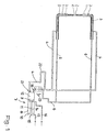
- a first embodiment is shown with Figure 1 and Figure 3 and below described.
- the electrode arms 1 of a spot welding gun are on their front ends connected with interchangeable electrode caps 2.
- each electrode arm 1 is a cooling water supply channel 3, each with a cooling water supply line 4 is connected to and from the electrode caps 2 formed tips of the electrode arms 1 leads.
- each of the tip of each electrode arm 1 leads to a cooling water return line 6.
- the cooling water supply pipe 4, from which the cooling water supply channels 3 branch off, is conveyed by a conveyor fed to convey cooling water.
- the conveyor has a cylinder-piston unit 7 and devices for controlled drive of the cylinder-piston unit 7.
- the cylinder-piston unit 7 comprises a cylinder 8 with a delivery piston 9 and a drive piston 10.
- the delivery piston 9 and the drive piston 10 are connected to each other by means of a piston rod 11. Both pistons are inside of the cylinder 8 can be moved together.
- a piston side of the delivery piston 9 delimits a pump chamber 12 while the other piston side the piston rod 11 is attached.
- the piston rod 11 penetrates a partition 13 of the cylinder 8.
- the partition 13 delimits a first working space 14 on one side of the drive piston 10.
- a second working space 15 is located on the other side of the working piston 10.
- the working rooms 14 and 15 are with Compressed air lines 16, 17 provided.
- the drive piston 10 depending on one Compressed air control, not shown here, can be moved anywhere in cylinder 8.
- the delivery piston 9 With the drive piston 10, the delivery piston 9 also moves in the cylinder 8 it goes without saying that at the passage of the piston rod 11 through the partition 13 Seal is provided, the escape of compressed air from the first work space 14 prevented at the passage point.
- the pump chamber 12 is connected via a line 18 to an expansion tank 19, wherein in line 18 in the direction from the pump chamber 12 to the surge tank 19 blocking check valve 20 is provided.
- the cooling water supply line 4 is connected to the pump chamber 2, wherein in immediate vicinity of the pump chamber 12 in the cooling water supply line 4 in Locking direction from the cooling water supply line 4 to the pump chamber 12 Check valve 21 is provided.
- the cooling water supply line 4 is, as indicated by the loop 22, laid that they also need other parts that require cooling, such as a welding transformer, reached.
- the expansion tank 19 is a cooler for the cooling water educated.
- To improve the heat exchange is an electrically driven one Cooling fan 23 is provided.
- the control of the resistance welding system specifies which one Performance a spot weld should be set. According to this achievement or A pneumatic valve, not shown here, also remains constant for each welding point controlled which compressed air through the compressed air line 17 in the Working space 15 conducts and at the same time vented the compressed air line 16. From pressure this compressed air is the working piston 10 and with it the delivery piston 9 in Cylinder 8 moves so that the pump chamber 12 is reduced.
- the one inside Cooling water is in a defined amount through the cooling water supply line 4 and the cooling water supply channels 3 to the welding electrodes on the electrode arms 1 pressed where it prevents inadmissible heating of the components. In the same Amount of cooling water flows through the cooling water return channels 5 and the cooling water return line 6 in the expansion tank 19. In the expansion tank 19 that Cooling water recooled.
- the control of the resistance welding system the aforementioned pneumatic valve is controlled so that the Compressed air line 16 compressed air is passed into the first work space 14 while the Compressed air line 17 and thus the second work space 15 is vented.
- the working piston 10 and with it the delivery piston 9 move in a direction in which the pump chamber 12 is enlarged.
- the pump chamber 12 is thereby Check valve 20 from the expansion tank 19 with recooled cooling water replenished.
- the check valve 21 on the cooling water supply line 4 remains closed.
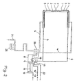
- FIG. 2 A second exemplary embodiment is shown in FIG. 2, the one compared to the first Embodiment functionally identical parts with the same reference numerals are.
- the cooling water from one central cooling water treatment system provided by a cooling water inlet 24.
- a thyristor control 25 to be cooled leads to a hydraulic OR gate 26.
- the hydraulic OR element gives 26 in the manner of a check valve the way for the cooling water from the Pump chamber 12 in the cooling water supply line 4 free.
- the expansion tank 19 becomes a small cooling water flow from the cooling water inlet 24 via the OR element 26 through the cooling water supply line 4, the cooling water supply channel 3, the cooling water return duct 5 and the cooling water return line 6 to the expansion tank 19 flow and through a cooling water drain 27 back to the central Cooling water treatment arrive.
- the device proposed for carrying out the method is relative low technical means feasible.
- the drive of the delivery piston 9 can done by any motor means.
- a pneumatic actuator offers is advantageous, however, since the majority of all welding machines anyway Compressed air is available for other movement processes.
- the device is also suitable for temporarily pumping the Cooling water from the electrode arms, such as with EP 0 433 586 B1 is described, in which, in addition to the check valves 20, 21 bypass lines are provided, which are released via controllable valves or be blocked. Additional equipment for the necessary pumping of the cooling water from the electrode arms are therefore not necessary.
Landscapes
- Engineering & Computer Science (AREA)
- Mechanical Engineering (AREA)
- Resistance Welding (AREA)
Abstract
Description
- Fig. 1
- das Schema einer Einrichtung zum Kühlen einer Punktschweißzange mit Wasserkühlung,
- Fig. 2
- das Schema einer Einrichtung zum Kühlen einer Punktschweißzange mit Einbeziehung der Thyristorstufe in den Kühlwasserkreislauf,
- Fig. 3
- eine vergrößerte Darstellung eines Details der Einrichtung nach Figur 1.
Claims (10)
- Verfahren zum Kühlen von Widerstandspunktschweißanlagen, insbesondere wassergekühlten Punktschweißzangen, mit einer sich zu den Schweißelektroden und weiteren zu kühlenden Teilen verzweigenden Kühlwasservorlaufleitung und einer die Kühlwasserrückläufe von den Schweißelektroden und den zu kühlenden Teilen aufnehmende Kühlwasserrücklaufleitung, mit je einem Absperrventil in der Kühlwasservorlaufleitung und in der Kühlwasserrücklaufleitung, mit einer Einrichtung zum Fördern von Kühlwasser unter Druck in die Kühlwasservorlaufleitung sowie mit einem Kühler zum Rückkühlen des Kühlwassers,
dadurch gekennzeichnet, dass ein Kühlwasserförderstrom zeitlich begrenzt nur während des operativen Schweißprozesses über die Kühlwasservorlaufleitung (4) an die zu kühlenden Stellen der Widerstandsschweißanlage und von diesen über die Kühlwasserrücklaufleitung (6) zum Kühler gefördert wird, während zwischen den operativen Schweißprozessen das Kühlwasser nicht über einen eventuellen Ruhestrom hinaus bewegt wird. - Verfahren nach Anspruch 1, dadurch gekennzeichnet, dass die Menge des pro operativen Schweißprozesses geförderten Kühlwassers abhängig ist von der aktuellen Schweißleistung.
- Einrichtung zum Kühlen von Widerstandsschweißanlagen, insbesondere wassergekühlten Punktschweißzangen mit einer sich zu den Schweißelektroden und weiteren zu kühlenden Teilen verzweigenden Kühlwasservorlaufleitung und einer die Kühlwasserrückläufe von den Schweißelektroden und den zu kühlenden Teilen aufnehmenden Kühlwasserrücklaufleitung mit je einem Absperrventil in der Kühlwasservorlaufleitung und in der Kühlwasserrücklaufleitung, mit einer Fördereinrichtung zum Fördern von Kühlwasser unter Druck in die Kühlwasservorlaufleitung sowie mit einem Kühler zum Rückkühlen des Kühlwassers - zur Durchführung des Verfahrens nach Anspruch 1 oder 2 -, dadurch gekennzeichnet, dass die Fördereinrichtung eine Zylinder-Kolbeneinheit (7) aufweist, wobei eine Kolbenseite eines Förderkolbens (9) im Zylinder (8) einen Pumpenraum (12) begrenzt, dessen Volumen dem Kühlwasserbedarf eines Schweißprozesses entspricht und der Förderkolben (9) mit einem motorischen Antrieb verbunden ist, der Pumpenraum (12) mit der Kühlwasservorlaufleitung (4) und der Kühlwasserrücklaufleitung (6) in Verbindung steht, wobei die Absperrventile in der Kühlwasservorlaufleitung (4) sowie in der Kühlwasserrücklaufleitung (6) als in Richtung des Kühlwasserstromes öffnende Rückschlagventile (20, 21) ausgebildet sind.
- Einrichtung nach Anspruch 3, dadurch gekennzeichnet, dass der motorische Antrieb des Förderkolbens (9) von einem gleichachsig mit dem Förderkolben (9) verbunden, alternativ beidseitig von einem Druckmedium beaufschlagbaren Antriebskolben (10) gebildet ist und/oder dass der motorische Antrieb des Förderkolbens (9) ein Elektroantrieb ist.
- Einrichtung nach Anspruch 3, dadurch gekennzeichnet, dass sich im Verlauf der Kühlwasserrücklaufleitung (6) ein Ausgleichsbehälter (19) befindet und das als Rückschlagventil (20) ausgebildete Absperrventil im Strömungsverlauf des Kühlmittels nach dem Ausgleichsbehälter (19) angeordnet ist und/oder dass der Ausgleichsbehälter (19) als Kühler ausgebildet ist, wobei der Ausgleichsbehälter (19) vorzugsweise als Wasser-Lufwärmetauscher ausgebildet ist und die Kühlluft von einem fremd angetriebenen Kühlgebläse (23) bereitgestellt wird.
- Einrichtung nach den Ansprüchen 3 bis 5, dadurch gekennzeichnet, dass in die Kühlwasservorlaufleitung (4) ein Kühlkreis (Schleife 22) zum Kühlen eines Schweißtransformators eingezogen ist und/oder dass eine für die Steuerung des Schweißtransformators vorgesehene Thyristorstufe (25) mit Luft gekühlt ist, wobei vorzugsweise sowohl ein Schweißtransformator als auch eine Thyristorstufe (25) in einen Kühlkreis der Kühlwasservorlaufleitung (4) oder Kühlwasserrücklaufleitung (6) einbezogen sind.
- Einrichtung nach den Ansprüchen 3 bis 5, dadurch gekennzeichnet, dass in die Kühlwasservorlaufleitung (4) ein als Oder-Glied (26) wirkendes Ventil einbezogen ist, welches einen über die Thyristorstufe (25) und einen Schweißtransformator führenden Kühlwasserzulauf (24) aufnimmt und vom Ausgleichsbehälter (19) ein Kühlwasserablauf (27) vorgesehen ist.
- Einrichtung nach den Ansprüchen 3 bis 7, dadurch gekennzeichnet, dass im Verlauf der Kühlwasservorlaufleitung (4) und in der Kühlwasserrücklaufleitung (6) ansteuerbare Ventile vorgesehen sind und die Fördereinrichtung in an sich bekannter Weise als Absaugpumpe für das Kühlwasser in den Elektrodenarmen (1) dient.
- Einrichtung nach den Ansprüchen 3 oder 4, dadurch gekennzeichnet, dass als Druckmedium zur Beaufschlagung des Antriebskolbens (10) Druckluft vorgesehen ist und/oder dass das an der pneumatisch angetriebenen Schweißzange ohnehin vorhandene 5/2-Wege-Ventil als Steuerelement für die Kühleinrichtung dient.
- Einrichtung nach Anspruch 3 oder 4, dadurch gekennzeichnet, dass das Rückschlagventil (21) mit einer einstellbaren Durchflussmengendrossel ausgestattet ist, die eine Regulierung des Kühlförderstromes ermöglicht und/oder dass in der Druckluftleitung (16, 17) eine einstellbare Reguliereinrichtung für die Einstellung des Wasserförderstromes für die Kühlung und für die Rückbefüllung des Arbeitsraumes (12) eingebaut ist.
Applications Claiming Priority (2)
| Application Number | Priority Date | Filing Date | Title |
|---|---|---|---|
| DE10101787 | 2001-01-17 | ||
| DE10101787A DE10101787B4 (de) | 2001-01-17 | 2001-01-17 | Verfahren zum Kühlen von Widerstandspunktschweißanlagen, insbesondere wassergekühlten Punktschweißzangen, und Einrichtung zur Durchführung des Verfahrens |
Publications (3)
| Publication Number | Publication Date |
|---|---|
| EP1224996A2 true EP1224996A2 (de) | 2002-07-24 |
| EP1224996A3 EP1224996A3 (de) | 2004-01-14 |
| EP1224996B1 EP1224996B1 (de) | 2006-07-12 |
Family
ID=7670737
Family Applications (1)
| Application Number | Title | Priority Date | Filing Date |
|---|---|---|---|
| EP02000443A Expired - Lifetime EP1224996B1 (de) | 2001-01-17 | 2002-01-08 | Verfahren zum Kühlen von Widerstandspunktschweissanlagen, insbesondere wassergekühlten Punktschweisszangen, und Einrichtung zur Durchführung des Verfahrens |
Country Status (4)
| Country | Link |
|---|---|
| EP (1) | EP1224996B1 (de) |
| AT (1) | ATE332783T1 (de) |
| DE (2) | DE10101787B4 (de) |
| ES (1) | ES2269525T3 (de) |
Cited By (2)
| Publication number | Priority date | Publication date | Assignee | Title |
|---|---|---|---|---|
| EP1688205A1 (de) * | 2005-02-03 | 2006-08-09 | Bürkert Werke GmbH & Co. KG | Vorrichtung zum Kühlen von Schweisskappen |
| DE102016217514A1 (de) | 2016-09-14 | 2018-03-15 | Volkswagen Aktiengesellschaft | Widerstandsschweißverfahren und Einrichtung zum Widerstandsschweißen |
Families Citing this family (8)
| Publication number | Priority date | Publication date | Assignee | Title |
|---|---|---|---|---|
| RU2420378C2 (ru) * | 2009-03-02 | 2011-06-10 | Кожокин Тимофей Иванович | Способ охлаждения электрода контактной точечной сварки (ктс) и устройство его реализации |
| DE102013200994A1 (de) | 2013-01-22 | 2014-07-24 | Dieter Klein | Verfahren zum Kühlen einer Elektrodenkappe in einer Schweißanlage undSchweißanlage zur Durchführung des Verfahrens |
| US10022815B2 (en) | 2014-09-09 | 2018-07-17 | Proteus Industries Inc. | Drawback valve systems and methods for coolant drawback |
| DE102014016338A1 (de) | 2014-11-05 | 2016-05-12 | Audi Ag | Widerstandspunktschweißvorrichtung |
| BR202016012661U2 (pt) * | 2016-06-03 | 2017-12-19 | Powermig Automação E Soldagem Ltda | Constructive provision in the system of cooling of welding machines, plasma or laser cutting |
| RU2622192C1 (ru) * | 2016-10-10 | 2017-06-13 | Кожокин Тимофей Иванович | Электрододержатель для контактной точечной сварки (КТС) |
| DE102019204208B4 (de) * | 2019-02-28 | 2024-08-01 | Christian Günther | Vorrichtung zur Kühlwasserabsaugung für eine Roboterinstallationsplatte mit einstellbarem Absaugvolumen |
| DE102024104080B4 (de) * | 2024-02-14 | 2025-10-09 | Lisa Dräxlmaier GmbH | Verfahren zur bedarfsgerechten Kühlung einer Fügewerkzeugeinheit einer Fügeanlage sowie eine Fügeanlage zur Durchführung eines solchen Verfahrens |
Family Cites Families (11)
| Publication number | Priority date | Publication date | Assignee | Title |
|---|---|---|---|---|
| US2629804A (en) * | 1951-05-26 | 1953-02-24 | Fred A Van Vooren | Water cooling and saving arrangement for electrical welders |
| GB872698A (en) * | 1958-09-13 | 1961-07-12 | Triangle Products Ltd | Improvements relating to spot welding machines |
| FR1562884A (de) * | 1967-12-21 | 1969-04-11 | ||
| FR2403154A1 (fr) * | 1977-09-14 | 1979-04-13 | Humblot Bernard | Dispositif economiseur d'eau de refroidissement dans une machine a souder par resistance et machine pourvue d'un tel dispositif |
| JPS5779085A (en) * | 1980-11-05 | 1982-05-18 | Kikuchi Kogyo Kk | Cooler for electric welding machine |
| DE3316868A1 (de) * | 1983-05-07 | 1984-05-17 | Daimler-Benz Ag, 7000 Stuttgart | Kuehlwasserabsaugvorrichtung fuer widerstandsschweissanlagen |
| JPS626781A (ja) * | 1985-07-02 | 1987-01-13 | Daihatsu Motor Co Ltd | スポツト溶接機 |
| JPS629784A (ja) * | 1985-07-04 | 1987-01-17 | Daihatsu Motor Co Ltd | スポツト溶接機 |
| DE3942105C1 (de) * | 1989-12-20 | 1991-04-25 | Liv Automation Gmbh, 5000 Koeln, De | |
| DE9420225U1 (de) * | 1994-12-20 | 1995-03-02 | Lindauer Dornier Gmbh, 88131 Lindau | Punktschweißmaschine, insbesondere Punktschweißzange |
| DE19828798A1 (de) * | 1998-06-27 | 1999-12-30 | Opel Adam Ag | Schweißelektrode |
-
2001
- 2001-01-17 DE DE10101787A patent/DE10101787B4/de not_active Expired - Fee Related
-
2002
- 2002-01-08 EP EP02000443A patent/EP1224996B1/de not_active Expired - Lifetime
- 2002-01-08 ES ES02000443T patent/ES2269525T3/es not_active Expired - Lifetime
- 2002-01-08 AT AT02000443T patent/ATE332783T1/de active
- 2002-01-08 DE DE50207458T patent/DE50207458D1/de not_active Expired - Lifetime
Cited By (3)
| Publication number | Priority date | Publication date | Assignee | Title |
|---|---|---|---|---|
| EP1688205A1 (de) * | 2005-02-03 | 2006-08-09 | Bürkert Werke GmbH & Co. KG | Vorrichtung zum Kühlen von Schweisskappen |
| US7598472B2 (en) | 2005-02-03 | 2009-10-06 | Burkert Werke Gmbh & Co. Kg | Device for cooling welding caps |
| DE102016217514A1 (de) | 2016-09-14 | 2018-03-15 | Volkswagen Aktiengesellschaft | Widerstandsschweißverfahren und Einrichtung zum Widerstandsschweißen |
Also Published As
| Publication number | Publication date |
|---|---|
| ES2269525T3 (es) | 2007-04-01 |
| DE10101787A1 (de) | 2002-07-18 |
| DE10101787B4 (de) | 2005-01-27 |
| EP1224996A3 (de) | 2004-01-14 |
| EP1224996B1 (de) | 2006-07-12 |
| ATE332783T1 (de) | 2006-08-15 |
| DE50207458D1 (de) | 2006-08-24 |
Similar Documents
| Publication | Publication Date | Title |
|---|---|---|
| DE69916775T2 (de) | Betätigungsmechanismus für ein Ventilteil einer Spritzgiessvorrichtung | |
| DE3403776A1 (de) | Verfahren und einrichtung zur pruefung eines brennstoffinjektors | |
| EP0808422A1 (de) | Verfahren und vorrichtung zum fördern von beton | |
| DE102007044091A1 (de) | Verfahren und Vorrichtung zur elektochemischen Bearbeitung | |
| EP1224996B1 (de) | Verfahren zum Kühlen von Widerstandspunktschweissanlagen, insbesondere wassergekühlten Punktschweisszangen, und Einrichtung zur Durchführung des Verfahrens | |
| DE1203169B (de) | Steuer- und Schaltvorrichtung fuer hydraulisch angetriebene Changiereinrichtungen bei Spinn-, Spul- und insbesondere Ringzwirnmaschinen | |
| DE10332290B4 (de) | Elektromagnetisches Ventil | |
| DE102020100669A1 (de) | Lineares Transportsystem sowie Motormodul und Führungsschiene für ein solches lineares Transportsystem | |
| DE112007002618B4 (de) | Fluidsteuerventil | |
| DE2954232C2 (de) | Hydraulische Presse | |
| DE2254033A1 (de) | Vorrichtung zum punktweisen auftragen eines klebstoffes | |
| EP2563541A2 (de) | Anordnung, verfahren und steuerung zur zufuhr eines hilfsstoffs | |
| DE69303671T2 (de) | Intermittierende Heizvorrichtung für plastifizierte Fluide in Spritzgiessen oder dergleichen | |
| DE1601732A1 (de) | Hydraulische Anlage | |
| DE1301697B (de) | Vorrichtung zur elektrolytischen Bearbeitung von langgestreckten Werkstuecken | |
| DE10225847A1 (de) | Funkenerosionseinrichtung | |
| DE1552110C3 (de) | Band-Richt- und Zerteilanlage | |
| DE19612411A1 (de) | Schmiervorrichtung für Schmiedegesenke | |
| DE2025392A1 (de) | Vorrichtung und Verfahren zur elektrochemischen Metallabtragung | |
| DE1565739C3 (de) | Verfahren zum elektrischen Widerslands-Rollen-NahtschweiBen | |
| DE202017107534U1 (de) | Kühlmedien-Absaugvorrichtung für Schweißzangen | |
| DE4203056C2 (de) | Schweißaggregat, insbesondere für Vielpunktschweißmaschinen | |
| DE69931037T2 (de) | Schweissgerät | |
| DE4447611A1 (de) | Hydraulischer Druckübersetzer und Verwendung eines solchen in einem Wasserhydraulikschweißsystem | |
| AT400941B (de) | Einrichtung zur versorgung von hydraulischen verbrauchern einer spritzgiessmaschine mit einer unter druck stehenden hydraulikflüssigkeit |
Legal Events
| Date | Code | Title | Description |
|---|---|---|---|
| PUAI | Public reference made under article 153(3) epc to a published international application that has entered the european phase |
Free format text: ORIGINAL CODE: 0009012 |
|
| AK | Designated contracting states |
Kind code of ref document: A2 Designated state(s): AT BE CH CY DE DK ES FI FR GB GR IE IT LI LU MC NL PT SE TR |
|
| AX | Request for extension of the european patent |
Free format text: AL;LT;LV;MK;RO;SI |
|
| PUAL | Search report despatched |
Free format text: ORIGINAL CODE: 0009013 |
|
| AK | Designated contracting states |
Kind code of ref document: A3 Designated state(s): AT BE CH CY DE DK ES FI FR GB GR IE IT LI LU MC NL PT SE TR |
|
| AX | Request for extension of the european patent |
Extension state: AL LT LV MK RO SI |
|
| 17P | Request for examination filed |
Effective date: 20040127 |
|
| 17Q | First examination report despatched |
Effective date: 20040603 |
|
| AKX | Designation fees paid |
Designated state(s): AT BE CH CY DE DK ES FI FR GB GR IE IT LI LU MC NL PT SE TR |
|
| GRAP | Despatch of communication of intention to grant a patent |
Free format text: ORIGINAL CODE: EPIDOSNIGR1 |
|
| GRAS | Grant fee paid |
Free format text: ORIGINAL CODE: EPIDOSNIGR3 |
|
| GRAA | (expected) grant |
Free format text: ORIGINAL CODE: 0009210 |
|
| AK | Designated contracting states |
Kind code of ref document: B1 Designated state(s): AT BE CH CY DE DK ES FI FR GB GR IE IT LI LU MC NL PT SE TR |
|
| PG25 | Lapsed in a contracting state [announced via postgrant information from national office to epo] |
Ref country code: IT Free format text: LAPSE BECAUSE OF FAILURE TO SUBMIT A TRANSLATION OF THE DESCRIPTION OR TO PAY THE FEE WITHIN THE PRESCRIBED TIME-LIMIT;WARNING: LAPSES OF ITALIAN PATENTS WITH EFFECTIVE DATE BEFORE 2007 MAY HAVE OCCURRED AT ANY TIME BEFORE 2007. THE CORRECT EFFECTIVE DATE MAY BE DIFFERENT FROM THE ONE RECORDED. Effective date: 20060712 Ref country code: NL Free format text: LAPSE BECAUSE OF FAILURE TO SUBMIT A TRANSLATION OF THE DESCRIPTION OR TO PAY THE FEE WITHIN THE PRESCRIBED TIME-LIMIT Effective date: 20060712 Ref country code: IE Free format text: LAPSE BECAUSE OF FAILURE TO SUBMIT A TRANSLATION OF THE DESCRIPTION OR TO PAY THE FEE WITHIN THE PRESCRIBED TIME-LIMIT Effective date: 20060712 Ref country code: FI Free format text: LAPSE BECAUSE OF FAILURE TO SUBMIT A TRANSLATION OF THE DESCRIPTION OR TO PAY THE FEE WITHIN THE PRESCRIBED TIME-LIMIT Effective date: 20060712 |
|
| REG | Reference to a national code |
Ref country code: GB Ref legal event code: FG4D Free format text: NOT ENGLISH |
|
| REG | Reference to a national code |
Ref country code: CH Ref legal event code: EP |
|
| PG25 | Lapsed in a contracting state [announced via postgrant information from national office to epo] |
Ref country code: DE Free format text: LAPSE BECAUSE OF THE APPLICANT RENOUNCES Effective date: 20060823 |
|
| REG | Reference to a national code |
Ref country code: IE Ref legal event code: FG4D Free format text: LANGUAGE OF EP DOCUMENT: GERMAN |
|
| REF | Corresponds to: |
Ref document number: 50207458 Country of ref document: DE Date of ref document: 20060824 Kind code of ref document: P |
|
| PG25 | Lapsed in a contracting state [announced via postgrant information from national office to epo] |
Ref country code: DK Free format text: LAPSE BECAUSE OF FAILURE TO SUBMIT A TRANSLATION OF THE DESCRIPTION OR TO PAY THE FEE WITHIN THE PRESCRIBED TIME-LIMIT Effective date: 20061012 |
|
| GBT | Gb: translation of ep patent filed (gb section 77(6)(a)/1977) |
Effective date: 20060921 |
|
| REG | Reference to a national code |
Ref country code: SE Ref legal event code: TRGR |
|
| PG25 | Lapsed in a contracting state [announced via postgrant information from national office to epo] |
Ref country code: PT Free format text: LAPSE BECAUSE OF FAILURE TO SUBMIT A TRANSLATION OF THE DESCRIPTION OR TO PAY THE FEE WITHIN THE PRESCRIBED TIME-LIMIT Effective date: 20061212 |
|
| NLV1 | Nl: lapsed or annulled due to failure to fulfill the requirements of art. 29p and 29m of the patents act | ||
| PG25 | Lapsed in a contracting state [announced via postgrant information from national office to epo] |
Ref country code: MC Free format text: LAPSE BECAUSE OF NON-PAYMENT OF DUE FEES Effective date: 20070131 Ref country code: CH Free format text: LAPSE BECAUSE OF NON-PAYMENT OF DUE FEES Effective date: 20070131 Ref country code: LI Free format text: LAPSE BECAUSE OF NON-PAYMENT OF DUE FEES Effective date: 20070131 |
|
| REG | Reference to a national code |
Ref country code: IE Ref legal event code: FD4D |
|
| ET | Fr: translation filed | ||
| REG | Reference to a national code |
Ref country code: ES Ref legal event code: FG2A Ref document number: 2269525 Country of ref document: ES Kind code of ref document: T3 |
|
| PLBE | No opposition filed within time limit |
Free format text: ORIGINAL CODE: 0009261 |
|
| STAA | Information on the status of an ep patent application or granted ep patent |
Free format text: STATUS: NO OPPOSITION FILED WITHIN TIME LIMIT |
|
| 26N | No opposition filed |
Effective date: 20070413 |
|
| REG | Reference to a national code |
Ref country code: CH Ref legal event code: PL |
|
| PG25 | Lapsed in a contracting state [announced via postgrant information from national office to epo] |
Ref country code: GR Free format text: LAPSE BECAUSE OF FAILURE TO SUBMIT A TRANSLATION OF THE DESCRIPTION OR TO PAY THE FEE WITHIN THE PRESCRIBED TIME-LIMIT Effective date: 20061013 |
|
| PG25 | Lapsed in a contracting state [announced via postgrant information from national office to epo] |
Ref country code: LU Free format text: LAPSE BECAUSE OF NON-PAYMENT OF DUE FEES Effective date: 20070108 Ref country code: CY Free format text: LAPSE BECAUSE OF FAILURE TO SUBMIT A TRANSLATION OF THE DESCRIPTION OR TO PAY THE FEE WITHIN THE PRESCRIBED TIME-LIMIT Effective date: 20060712 |
|
| PG25 | Lapsed in a contracting state [announced via postgrant information from national office to epo] |
Ref country code: TR Free format text: LAPSE BECAUSE OF FAILURE TO SUBMIT A TRANSLATION OF THE DESCRIPTION OR TO PAY THE FEE WITHIN THE PRESCRIBED TIME-LIMIT Effective date: 20060712 |
|
| PGFP | Annual fee paid to national office [announced via postgrant information from national office to epo] |
Ref country code: AT Payment date: 20110113 Year of fee payment: 10 |
|
| REG | Reference to a national code |
Ref country code: AT Ref legal event code: MM01 Ref document number: 332783 Country of ref document: AT Kind code of ref document: T Effective date: 20120108 |
|
| PG25 | Lapsed in a contracting state [announced via postgrant information from national office to epo] |
Ref country code: AT Free format text: LAPSE BECAUSE OF NON-PAYMENT OF DUE FEES Effective date: 20120108 |
|
| REG | Reference to a national code |
Ref country code: FR Ref legal event code: PLFP Year of fee payment: 15 |
|
| REG | Reference to a national code |
Ref country code: FR Ref legal event code: PLFP Year of fee payment: 16 |
|
| REG | Reference to a national code |
Ref country code: FR Ref legal event code: PLFP Year of fee payment: 17 |
|
| PGFP | Annual fee paid to national office [announced via postgrant information from national office to epo] |
Ref country code: FR Payment date: 20210121 Year of fee payment: 20 |
|
| PGFP | Annual fee paid to national office [announced via postgrant information from national office to epo] |
Ref country code: SE Payment date: 20210120 Year of fee payment: 20 Ref country code: BE Payment date: 20210120 Year of fee payment: 20 Ref country code: ES Payment date: 20210324 Year of fee payment: 20 Ref country code: GB Payment date: 20210121 Year of fee payment: 20 |
|
| PGFP | Annual fee paid to national office [announced via postgrant information from national office to epo] |
Ref country code: IT Payment date: 20210121 Year of fee payment: 20 |
|
| REG | Reference to a national code |
Ref country code: GB Ref legal event code: PE20 Expiry date: 20220107 |
|
| REG | Reference to a national code |
Ref country code: BE Ref legal event code: MK Effective date: 20220108 |
|
| REG | Reference to a national code |
Ref country code: ES Ref legal event code: FD2A Effective date: 20220426 |
|
| PG25 | Lapsed in a contracting state [announced via postgrant information from national office to epo] |
Ref country code: GB Free format text: LAPSE BECAUSE OF EXPIRATION OF PROTECTION Effective date: 20220107 |
|
| PG25 | Lapsed in a contracting state [announced via postgrant information from national office to epo] |
Ref country code: ES Free format text: LAPSE BECAUSE OF EXPIRATION OF PROTECTION Effective date: 20220109 |