EP1225082A2 - Dispositif de commande pour un véhicule à propulsion de pile à combustible - Google Patents
Dispositif de commande pour un véhicule à propulsion de pile à combustible Download PDFInfo
- Publication number
- EP1225082A2 EP1225082A2 EP02000539A EP02000539A EP1225082A2 EP 1225082 A2 EP1225082 A2 EP 1225082A2 EP 02000539 A EP02000539 A EP 02000539A EP 02000539 A EP02000539 A EP 02000539A EP 1225082 A2 EP1225082 A2 EP 1225082A2
- Authority
- EP
- European Patent Office
- Prior art keywords
- electric motor
- temperature
- fuel cell
- power plant
- cell power
- Prior art date
- Legal status (The legal status is an assumption and is not a legal conclusion. Google has not performed a legal analysis and makes no representation as to the accuracy of the status listed.)
- Withdrawn
Links
Images



Classifications
-
- B—PERFORMING OPERATIONS; TRANSPORTING
- B60—VEHICLES IN GENERAL
- B60L—PROPULSION OF ELECTRICALLY-PROPELLED VEHICLES; SUPPLYING ELECTRIC POWER FOR AUXILIARY EQUIPMENT OF ELECTRICALLY-PROPELLED VEHICLES; ELECTRODYNAMIC BRAKE SYSTEMS FOR VEHICLES IN GENERAL; MAGNETIC SUSPENSION OR LEVITATION FOR VEHICLES; MONITORING OPERATING VARIABLES OF ELECTRICALLY-PROPELLED VEHICLES; ELECTRIC SAFETY DEVICES FOR ELECTRICALLY-PROPELLED VEHICLES
- B60L58/00—Methods or circuit arrangements for monitoring or controlling batteries or fuel cells, specially adapted for electric vehicles
- B60L58/30—Methods or circuit arrangements for monitoring or controlling batteries or fuel cells, specially adapted for electric vehicles for monitoring or controlling fuel cells
- B60L58/32—Methods or circuit arrangements for monitoring or controlling batteries or fuel cells, specially adapted for electric vehicles for monitoring or controlling fuel cells for controlling the temperature of fuel cells, e.g. by controlling the electric load
- B60L58/33—Methods or circuit arrangements for monitoring or controlling batteries or fuel cells, specially adapted for electric vehicles for monitoring or controlling fuel cells for controlling the temperature of fuel cells, e.g. by controlling the electric load by cooling
-
- B—PERFORMING OPERATIONS; TRANSPORTING
- B60—VEHICLES IN GENERAL
- B60L—PROPULSION OF ELECTRICALLY-PROPELLED VEHICLES; SUPPLYING ELECTRIC POWER FOR AUXILIARY EQUIPMENT OF ELECTRICALLY-PROPELLED VEHICLES; ELECTRODYNAMIC BRAKE SYSTEMS FOR VEHICLES IN GENERAL; MAGNETIC SUSPENSION OR LEVITATION FOR VEHICLES; MONITORING OPERATING VARIABLES OF ELECTRICALLY-PROPELLED VEHICLES; ELECTRIC SAFETY DEVICES FOR ELECTRICALLY-PROPELLED VEHICLES
- B60L58/00—Methods or circuit arrangements for monitoring or controlling batteries or fuel cells, specially adapted for electric vehicles
- B60L58/30—Methods or circuit arrangements for monitoring or controlling batteries or fuel cells, specially adapted for electric vehicles for monitoring or controlling fuel cells
-
- Y—GENERAL TAGGING OF NEW TECHNOLOGICAL DEVELOPMENTS; GENERAL TAGGING OF CROSS-SECTIONAL TECHNOLOGIES SPANNING OVER SEVERAL SECTIONS OF THE IPC; TECHNICAL SUBJECTS COVERED BY FORMER USPC CROSS-REFERENCE ART COLLECTIONS [XRACs] AND DIGESTS
- Y02—TECHNOLOGIES OR APPLICATIONS FOR MITIGATION OR ADAPTATION AGAINST CLIMATE CHANGE
- Y02T—CLIMATE CHANGE MITIGATION TECHNOLOGIES RELATED TO TRANSPORTATION
- Y02T90/00—Enabling technologies or technologies with a potential or indirect contribution to GHG emissions mitigation
- Y02T90/40—Application of hydrogen technology to transportation, e.g. using fuel cells
Definitions
- This invention relates to a control device for a vehicle which is powered by a fuel cell.
- Tokkai Hei 9-191582 published by the Japanese Patent Office in 1997 discloses a system which performs output limitation of the direct current (DC) power supply in order to prevent increase in the temperature of the electric motor. Reduction of the input voltage of the electric motor leads to elevation of its temperature, and to increase in the heat loss in the motor. This prior art reduces the output of the DC power supply in such a case, so as to decrease the input current to the electric motor.
- DC direct current
- Tokkai Hei 11-220812 published by the Japanese Patent Office in 1999 discloses an electric system which enhances the operational efficiency of the electric motor by keeping the input voltage to the electric motor at a constant potential level by output voltage control of the DC power supply.
- limitation of the output of the DC power supply amounts to a limitation of the output of the electric motor, and as a result the power performance of the vehicle is reduced.
- this invention provides a control device for fuel cell powered vehicle which is driven by an electric motor to which a fuel cell power plant and a rechargeable battery are electrically connected in parallel.
- the device comprises a converter which converts an output voltage of one of the fuel cell power plant and the rechargeable battery, a temperature sensor which detects a temperature of the electric motor, and a programmable controller programmed to control an output voltage of the converter according to the temperature of the electric motor.
- This invention also provides a control method for a fuel cell powered vehicle which is driven by an electric motor to which a fuel cell power plant and a rechargeable battery are electrically connected in parallel.
- the method comprises detecting a temperature of the electric motor, and converting an output voltage of one of the fuel cell power plant and the rechargeable battery according to the temperature of the electric motor.
- FIG. 1 is a schematic diagram of a control device for a fuel cell powered vehicle according to this invention.
- FIG. 2 is a flow chart for explanation of a control routine for the output voltage of a fuel cell power plant, which is executed by a controller according to this invention.
- FIG. 3 is a diagram showing a relationship between the coil temperature of an electric motor and a set voltage defined by the controller.
- FIG. 4 is a diagram showing a possible variation related to the relationship between the electric motor coil temperature and the set voltage defined by the controller.
- FIG. 5 is a diagram showing another variation related to the relationship between the electric motor coil temperature and the set voltage that can be defined by the controller.
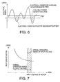
- FIG. 6 is a diagram showing the variation of the output voltage of the fuel cell power plant when the plant is operating with the highest efficiency.
- FIG. 7 is a diagram for explanation of a relationship between input voltage to the electric motor and heat loss in the motor.
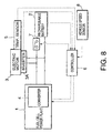
- FIG. 8 is similar to FIG. 1 but showing a second embodiment of this invention.
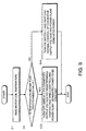
- FIG. 9 is similar to FIG. 2 but showing the second embodiment of this invention.
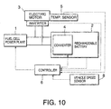
- FIG. 10 is similar to FIG. 1 but showing a third embodiment of this invention.
- FIG. 11 is similar to FIG. 2 but showing the third embodiment of this invention.
- a fuel cell powered vehicle comprises an electric motor 3 which provides its motive power, a fuel cell power plant 1 which comprises a fuel cell stack for supplying electrical power to the electric motor 3, and a rechargeable battery 2.
- the fuel cell power plant 1 comprises a fuel cell which generates electrical power by utilizing hydrogen.
- a 20 kilowatt (KW) three phase synchronous alternating current (AC) motor is used as the electric motor 3.
- This electric motor 3 comprises an inverter 3A.
- the fuel cell device 1 and the rechargeable battery 2 are connected to the inverter 3A in parallel, as shown in the figure by solid lines.
- the inverter 3A converts the direct current (DC) which is supplied from this parallel power supply circuit into three phase alternating current (AC), which it supplies to the electric motor 3.
- the electric motor 3 is rotated by this three phase alternating current, and drives the drive wheels of the vehicle.
- the rotational energy of the drive wheels regenerates electrical energy by driving the electric motor 3 as a generator, so as to charge the rechargeable battery 2.
- the fuel cell power plant supplies drive current to the electric motor 1. Moreover, when the voltage of the rechargeable battery 2 has dropped due to lack of charge, the fuel cell power plant supplies current to this rechargeable battery 2 for charging it.
- a converter 4 is provided to the fuel cell power plant 1 for increasing its output voltage.
- This converter 4 is a so-called DC-DC converter, and increases the output voltage of the fuel cell power plant 1 according to a signal which is output from the controller 6.
- a temperature sensor 5 which detects the temperature of the electric motor 3 and a vehicle speed sensor 8 which detects the vehicle speed are connected to the controller 6 by a signal circuit shown by the broken lines in the figure.
- the temperature sensor 5 detects the temperature of a coil which is provided to the electric motor 3, or the temperature of coolant which cools the electric motor 3.
- a signal from the rechargeable battery 2 which indicates its output voltage and a signal from the inverter 3A of the electric motor 3 which indicates the motor load are input to the controller 6.
- the controller 6 controls the converter 4 so as to control the output voltage of the fuel cell power plant 1.
- the controller 6 executes a routine shown in FIG. 2 at periodic intervals while the electric motor 3 is operating.
- the execution period may be, for example, one second.
- step S1 the controller 6 reads the motor temperature as detected by the temperature sensor 5.
- a step S2 the controller 6 compares this motor temperature with a predetermined temperature.
- This predetermined temperature may be set to a coil temperature of a hundred degrees centigrade (100°C). If the motor temperature is greater than the predetermined temperature, the routine proceeds to a step S3.
- the controller 6 controls the output voltage of the fuel cell power plant lto a predetermined high voltage value by outputting a signal to the converter 4.
- FIG. 3 shows the control range for the drive voltage for the electric motor 3.
- the predetermined high voltage value which is applied in the step S3 is set to be equal to the upper limit of this control range.
- the control range is 70 volts to 140 volts. Accordingly, in the step S3, the controller 6 controls the converter 4 so that the output voltage of the fuel cell power plant is equal to 140 volts. The output power of the fuel cell power plant 1 is maintained at a constant level which allows this voltage to be attained.
- the heat loss rate of the electric motor 3 increases along with decrease of its input voltage.
- the output voltage of the fuel cell device 1 is maintained at the upper limit of the control range, in order to ensure that the heat loss rate of the motor 3 is small.
- step S2 If in the step S2 it is determined that the motor temperature is not greater than the predetermined temperature value, the routine proceeds to a step S4.
- step S4 the controller 6 performs normal control in the above described control range. This control is performed for the purpose of maximizing the operational efficiency of the fuel cell power plant 1.
- the controller 6 controls the converter 4 so that it raises its output voltage higher than the open circuit voltage of the rechargeable battery 2.
- the controller 6 controls the converter 4 so that its output voltage is equal to the open circuit voltage of the rechargeable battery 2, so that electrical power is supplied to the electric motor 3 both from the fuel cell power plant 1 and also from the rechargeable battery 2.
- the controller 6 In parallel with controlling the output voltage of the converter 4, the controller 6 also controls the level of power generation of the fuel cell power plant 1 in the following manner.
- the power generation level for the fuel cell power plant 1 shown by the straight line in this figure is the level for which the efficiency is the highest.
- the curved line shows the variation of the electrical power requirement as the load upon the electric motor 3 changes.
- the surplus electrical power is used for charging the rechargeable battery 2.
- the most suitable operational efficiency for the fuel cell power plant 1 is that at which its power generation level is maintained so that the power supplied by the rechargeable battery 2 is equal to the electrical power used for charging the rechargeable battery 2.
- the power generation level of the fuel cell power plant 1 should be so adjusted that, in FIG. 7, the total area of the regions delimited by the required power curve below the straight line which shows the power generation level, in other words, the total area of the regions shown by the diagonal hatching, and the total area of the regions delimited by the required power curve above the straight line, should be equal to one another.
- Such adjustment of the power generation level of the fuel cell power plant 1 is performed by adjusting the amount of fuel which is supplied to the fuel cell power plant 1.
- the level of power generation is adjusted by adjusting the amount of fuel supplied for reformation; and, in the case of a fuel cell power plant which is not associated with any reformation device, the level of power generation is adjusted by adjusting the amount of hydrogen supplied.
- the output voltage control of the fuel cell power plant 1 in the vicinity of the predetermined temperature is stabilized by setting a hysteresis region in this manner.
- the routine would only proceed from the step S2 to the step S3 if both the temperature of the electric motor 3 was higher than the certain predetermined temperature and also the vehicle speed was higher than a certain predetermined vehicle speed while on the other hand, if the vehicle speed was lower than the predetermined vehicle speed, the routine would proceed to the step S4, even if the temperature of the electric motor 3 was higher than the predetermined temperature.
- the predetermined vehicle speed is set to a boundary speed between the low vehicle speed region and the medium to high vehicle speed region.
- the low vehicle speed region corresponds to the speed region for driving in urban areas.
- this type of slight rise of the temperature of the electric motor 3 in the low vehicle speed region is excluded from the range of phenomena subjected to temperature rise suppression control.
- heat loss in the electric motor 3 in the medium and high vehicle speed region is suppressed, while on the other hand it becomes possible to reduce the fuel consumption of the fuel cell power plant 1 in the low vehicle speed region.
- the temperature sensor 5 detects the temperature of the electric motor 3 from the temperature of its coil or from the temperature of its coolant, it would be possible, as an alternative, further to enhance the accuracy of control by detecting both of these two temperatures individually by using a plurality of temperature sensors, by comparing the temperatures detected by these plural sensors against separately set predetermined temperatures, and by performing determination of the temperature of the electric motor 3 based upon the results of these comparisons.
- control device in addition to the structure of the first embodiment described above, is further provided with a switch 7 as shown in FIG. 8.
- the switch 7 is normally kept in an ON state where it electrically connects the rechargeable battery 2 with the electric motor 3 and fuel cell power plant 1. It turns to an OFF state upon receiving a signal from the controller 6 to interrupt the electrical connection therebetween. 1.
- a step S3A is provided instead of the step S3 of the control routine of the first embodiment, and likewise a step S4A is provided instead of the step S4.
- the controller turns the switch 7 OFF and controls the output voltage of the converter 4to the predetermined high voltage value, in the same manner as in the step S3 described above.
- the step S4A along with turning the switch 7 ON, optimizing control of the operational efficiency of the fuel cell power plant 1 is performed in the same manner as in the step S4 described above.
- flow of electrical current to and from the rechargeable battery 2 is interrupted during the period in which control is being performed for suppressing elevation of the temperature of the electric motor 3.
- Maintaining the output voltage of the converter 4 at the predetermined high voltage value leads to increase of the load upon the fuel cell power plant 1. If the switch 7 is turned OFF during the period in which control is being performed for suppressing elevation of the temperature of the electric motor 3, no charging electrical current is provided to the rechargeable battery 2 from the fuel cell power plant 1, even if the charge level of the rechargeable battery 2 drops.
- no converter 4 is provided to the fuel cell power plant 1, but instead a converter 4 is provided to the rechargeable battery 2. Accordingly the converter 4 regulates, not the output voltage of the fuel cell power plant 1, but instead the output voltage of the rechargeable battery 2.
- a step S3B is provided instead of the step S3 of the control routine of the first embodiment, and likewise a step S4B is provided instead of the step S4.
- step S3B not only is the output voltage of the converter 4 controlled to the predetermined high voltage value, but also the power generated by the fuel cell power plant 1 is fixed at a constant level which can provide the predetermined high voltage value.
- the fuel cell stack of the fuel cell power plant 1 has the characteristic that, the lower is the output power, the higher is the voltage which it can output. Accordingly, if the fuel cell power plant 1 is made to output a high voltage value corresponding to the output voltage of the converter 4, the power generated by the fuel cell power plant 1 is kept low. In this case, the shortage of power required by the electric motor 3 is supplied from the rechargeable battery 2.
- step S4B the controller 6 controls the converter 4 so that its output voltage becomes lower than the output voltage of the fuel cell power plant 1. If the power required by the electric motor 3 is larger than the output power of the fuel cell power plant 1, the controller 6 controls the converter 4 so that the output voltage of the converter 4 becomes equal to the output voltage of the fuel cell power plant 1, thereby supplying electrical power to the electric motor 3 both from the fuel cell power plant 1 and from the rechargeable battery 2
- the controller 6 controls the power generated by the fuel cell power plant 1 so as to satisfy the relationship shown in FIG. 6.
- the power generated by the fuel cell power plant 1 is not increased during the period for temperature elevation suppression control of the electric motor 3. Accordingly, it is possible to prevent reduction of the load upon the fuel cell power plant 1 in accompaniment with temperature elevation suppression control of the electric motor 3.
Landscapes
- Engineering & Computer Science (AREA)
- Life Sciences & Earth Sciences (AREA)
- Sustainable Development (AREA)
- Sustainable Energy (AREA)
- Power Engineering (AREA)
- Transportation (AREA)
- Mechanical Engineering (AREA)
- Electric Propulsion And Braking For Vehicles (AREA)
- Fuel Cell (AREA)
Applications Claiming Priority (2)
| Application Number | Priority Date | Filing Date | Title |
|---|---|---|---|
| JP2001010917 | 2001-01-19 | ||
| JP2001010917A JP3598975B2 (ja) | 2001-01-19 | 2001-01-19 | 燃料電池自動車の制御装置 |
Publications (2)
| Publication Number | Publication Date |
|---|---|
| EP1225082A2 true EP1225082A2 (fr) | 2002-07-24 |
| EP1225082A3 EP1225082A3 (fr) | 2004-12-15 |
Family
ID=18878141
Family Applications (1)
| Application Number | Title | Priority Date | Filing Date |
|---|---|---|---|
| EP02000539A Withdrawn EP1225082A3 (fr) | 2001-01-19 | 2002-01-09 | Dispositif de commande pour un véhicule à propulsion de pile à combustible |
Country Status (3)
| Country | Link |
|---|---|
| US (1) | US6563288B2 (fr) |
| EP (1) | EP1225082A3 (fr) |
| JP (1) | JP3598975B2 (fr) |
Cited By (7)
| Publication number | Priority date | Publication date | Assignee | Title |
|---|---|---|---|---|
| WO2004054020A1 (fr) * | 2002-12-12 | 2004-06-24 | Sony Corporation | Dispositif monte sur pile a combustible et systeme d'alimentation electrique |
| WO2004021466A3 (fr) * | 2002-08-31 | 2004-07-01 | Daimler Chrysler Ag | Pile a combustible a regulation de puissance |
| WO2004079853A3 (fr) * | 2003-03-05 | 2005-08-11 | Gillette Co | Alimentation hybride de pile a combustible |
| US7862926B2 (en) | 2003-07-09 | 2011-01-04 | The Gillette Company | Fuel cartridge interconnect for portable fuel cells |
| DE102017214440A1 (de) * | 2017-08-18 | 2019-02-21 | Audi Ag | Verfahren zum Betreiben einer Brennstoffzellenanordnung sowie entsprechende Brennstoffzellenanordnung |
| US11342570B2 (en) | 2017-08-18 | 2022-05-24 | Audi Ag | Method for operating a fuel cell arrangement and also a corresponding fuel cell arrangement |
| EP4230470A1 (fr) * | 2022-02-16 | 2023-08-23 | Hyundai Mobis Co., Ltd. | Système et procédé de commande d'une sortie de système alimenté par une batterie et une pile à combustible |
Families Citing this family (14)
| Publication number | Priority date | Publication date | Assignee | Title |
|---|---|---|---|---|
| US20100209795A1 (en) * | 2001-10-31 | 2010-08-19 | Hardwicke Edward W | Power subsystem for a fuel cell system |
| JP2003189409A (ja) * | 2001-12-21 | 2003-07-04 | Toyota Motor Corp | 電動機搭載車両 |
| JP3750608B2 (ja) * | 2002-01-23 | 2006-03-01 | トヨタ自動車株式会社 | 車両における蓄電装置の制御装置 |
| JP4178986B2 (ja) * | 2003-02-13 | 2008-11-12 | トヨタ自動車株式会社 | 車両用電気機器の搭載構造 |
| JP2005224075A (ja) * | 2004-02-09 | 2005-08-18 | Sanyo Electric Co Ltd | インバータ装置 |
| US7145788B2 (en) * | 2004-07-27 | 2006-12-05 | Paccar Inc | Electrical power system for vehicles requiring electrical power while the vehicle engine is not in operation |
| JP4737533B2 (ja) * | 2005-12-28 | 2011-08-03 | スズキ株式会社 | 車両用制御装置 |
| JP4678374B2 (ja) * | 2007-01-04 | 2011-04-27 | トヨタ自動車株式会社 | 負荷装置の制御装置、および車両 |
| ATE536275T1 (de) † | 2007-03-06 | 2011-12-15 | Boeing Co | Hybride elektrische stromquelle |
| JP4395576B2 (ja) * | 2008-03-21 | 2010-01-13 | トヨタ自動車株式会社 | 電源制御装置 |
| CN102165684B (zh) * | 2008-09-29 | 2014-02-12 | 丰田自动车株式会社 | 车辆的电源装置 |
| US9561738B2 (en) * | 2011-10-26 | 2017-02-07 | Mitsubishi Electric Corporation | Control apparatus of electrically-driven vehicle |
| CN104852356B (zh) * | 2014-02-17 | 2018-09-21 | 伊顿公司 | 电动机的控制保护装置 |
| US20160264006A1 (en) * | 2015-03-09 | 2016-09-15 | M-Field Energy Ltd. | Hybrid electrical power system for industrial electric vehicle and method of operation thereof |
Family Cites Families (16)
| Publication number | Priority date | Publication date | Assignee | Title |
|---|---|---|---|---|
| US3774676A (en) * | 1972-03-28 | 1973-11-27 | Eaton Corp | Automotive vehicle automatic temperature control system |
| ZA764709B (en) * | 1976-01-26 | 1978-02-22 | Borg Warner | Catalytically active composition for electroless plating |
| US5350992A (en) * | 1991-09-17 | 1994-09-27 | Micro-Trak Systems, Inc. | Motor control circuit |
| US5227703A (en) * | 1992-04-21 | 1993-07-13 | General Electric Company | Protection system for alternating current, battery powered electric traction motor vehicle |
| JP3170969B2 (ja) * | 1993-09-16 | 2001-05-28 | トヨタ自動車株式会社 | ハイブリッド車のモータ電圧制御装置 |
| JPH07212915A (ja) * | 1994-01-20 | 1995-08-11 | Fuji Electric Co Ltd | 電気自動車駆動用電動機の制御方法 |
| JPH08275405A (ja) * | 1995-03-31 | 1996-10-18 | Mitsubishi Electric Corp | 内燃機関用充電制御装置 |
| JP3487952B2 (ja) * | 1995-04-14 | 2004-01-19 | 株式会社日立製作所 | 電気自動車の駆動装置及び駆動制御方法 |
| JP3341799B2 (ja) * | 1995-04-14 | 2002-11-05 | 株式会社日立製作所 | 電気自動車の制御装置 |
| JP3520645B2 (ja) | 1996-01-11 | 2004-04-19 | 日産自動車株式会社 | 電気自動車制御装置 |
| US5896487A (en) * | 1996-03-05 | 1999-04-20 | Masten; Billy Reese | Opto-electrically controlled direct current motor speed control circuit |
| JP4372235B2 (ja) * | 1996-08-29 | 2009-11-25 | トヨタ自動車株式会社 | 燃料電池システムおよび電気自動車 |
| US5950752A (en) * | 1997-11-21 | 1999-09-14 | Lockheed Martin Corp. | Heating system for a hybrid electric vehicle |
| JPH11220812A (ja) | 1998-02-02 | 1999-08-10 | Fuji Electric Co Ltd | 電気自動車の電気システム |
| JP2000036308A (ja) * | 1998-07-16 | 2000-02-02 | Toyota Motor Corp | 燃料電池システム |
| US6159626A (en) * | 1999-07-06 | 2000-12-12 | General Motors Corporation | Fuel cell system logic for differentiating between rapid and normal shutdown commands |
-
2001
- 2001-01-19 JP JP2001010917A patent/JP3598975B2/ja not_active Expired - Fee Related
-
2002
- 2002-01-03 US US10/034,256 patent/US6563288B2/en not_active Expired - Fee Related
- 2002-01-09 EP EP02000539A patent/EP1225082A3/fr not_active Withdrawn
Cited By (11)
| Publication number | Priority date | Publication date | Assignee | Title |
|---|---|---|---|---|
| WO2004021466A3 (fr) * | 2002-08-31 | 2004-07-01 | Daimler Chrysler Ag | Pile a combustible a regulation de puissance |
| WO2004054020A1 (fr) * | 2002-12-12 | 2004-06-24 | Sony Corporation | Dispositif monte sur pile a combustible et systeme d'alimentation electrique |
| US8222840B2 (en) | 2002-12-12 | 2012-07-17 | Sony Corporation | Fuel cell mount apparatus and electric power supply system |
| WO2004079853A3 (fr) * | 2003-03-05 | 2005-08-11 | Gillette Co | Alimentation hybride de pile a combustible |
| US7932634B2 (en) | 2003-03-05 | 2011-04-26 | The Gillette Company | Fuel cell hybrid power supply |
| US7862926B2 (en) | 2003-07-09 | 2011-01-04 | The Gillette Company | Fuel cartridge interconnect for portable fuel cells |
| DE102017214440A1 (de) * | 2017-08-18 | 2019-02-21 | Audi Ag | Verfahren zum Betreiben einer Brennstoffzellenanordnung sowie entsprechende Brennstoffzellenanordnung |
| US11271227B2 (en) | 2017-08-18 | 2022-03-08 | Audi Ag | Method for operating a fuel cell arrangement and a corresponding fuel cell arrangement |
| US11342570B2 (en) | 2017-08-18 | 2022-05-24 | Audi Ag | Method for operating a fuel cell arrangement and also a corresponding fuel cell arrangement |
| EP4230470A1 (fr) * | 2022-02-16 | 2023-08-23 | Hyundai Mobis Co., Ltd. | Système et procédé de commande d'une sortie de système alimenté par une batterie et une pile à combustible |
| US11784597B2 (en) | 2022-02-16 | 2023-10-10 | Hyundai Mobis Co., Ltd. | System and method for controlling output |
Also Published As
| Publication number | Publication date |
|---|---|
| US20020097020A1 (en) | 2002-07-25 |
| JP2002218607A (ja) | 2002-08-02 |
| JP3598975B2 (ja) | 2004-12-08 |
| US6563288B2 (en) | 2003-05-13 |
| EP1225082A3 (fr) | 2004-12-15 |
Similar Documents
| Publication | Publication Date | Title |
|---|---|---|
| US6563288B2 (en) | Control device for fuel cell powered vehicle | |
| JP5434196B2 (ja) | 燃料電池システム及びこれを備えた車両 | |
| US7196492B2 (en) | Power supply apparatus including fuel cell and capacitor, and operation method thereof | |
| JP5434195B2 (ja) | 燃料電池システム及びこれを備えた車両 | |
| US5945808A (en) | Hybrid electric vehicle with battery management | |
| US6727676B2 (en) | Control device for hybrid vehicle | |
| KR101846632B1 (ko) | 연료전지차량의 스탑모드시 전압 제어방법 | |
| EP1319548B1 (fr) | Véhicule hybride et méthode de régulation correspondante | |
| JP3638658B2 (ja) | 電池再充電装置および電池再充電方法 | |
| US10538167B2 (en) | Power supply system, transportation device, and power transmission method | |
| EP2988965B1 (fr) | Système de charge embarqué et son procédé de commande | |
| US11400818B2 (en) | Drive control apparatus for controlling vehicle drive system | |
| US7049788B2 (en) | Power source device for electric motor | |
| JP2003235252A (ja) | 電源回路 | |
| CN108281953A (zh) | 电力系统及其控制方法和设备 | |
| CN111746346B (zh) | 电源系统 | |
| JP5509655B2 (ja) | 燃料電池システム及びこれを備えた車両 | |
| JP2004350478A (ja) | 電圧変換システム、電圧変換方法および制御プログラム | |
| JP2005094917A (ja) | 燃料電池システム | |
| US20040239289A1 (en) | Method and system for controlling the charging of a vehicle battery | |
| JP2002151121A (ja) | 燃料電池発電システム | |
| WO2018155442A1 (fr) | Système d'alimentation en cc | |
| JP4495003B2 (ja) | 鉄道車両の蓄電装置暖機方法及び装置 | |
| JP6054918B2 (ja) | 2電源負荷駆動燃料電池システム及び燃料電池自動車 | |
| JP2002186194A (ja) | 電源装置 |
Legal Events
| Date | Code | Title | Description |
|---|---|---|---|
| PUAI | Public reference made under article 153(3) epc to a published international application that has entered the european phase |
Free format text: ORIGINAL CODE: 0009012 |
|
| 17P | Request for examination filed |
Effective date: 20020109 |
|
| AK | Designated contracting states |
Kind code of ref document: A2 Designated state(s): AT BE CH CY DE DK ES FI FR GB GR IE IT LI LU MC NL PT SE TR |
|
| AX | Request for extension of the european patent |
Free format text: AL;LT;LV;MK;RO;SI |
|
| PUAL | Search report despatched |
Free format text: ORIGINAL CODE: 0009013 |
|
| AK | Designated contracting states |
Kind code of ref document: A3 Designated state(s): AT BE CH CY DE DK ES FI FR GB GR IE IT LI LU MC NL PT SE TR |
|
| AX | Request for extension of the european patent |
Extension state: AL LT LV MK RO SI |
|
| AKX | Designation fees paid |
Designated state(s): DE FR GB |
|
| 17Q | First examination report despatched |
Effective date: 20060810 |
|
| STAA | Information on the status of an ep patent application or granted ep patent |
Free format text: STATUS: THE APPLICATION IS DEEMED TO BE WITHDRAWN |
|
| 18D | Application deemed to be withdrawn |
Effective date: 20080801 |