EP1225326B1 - Rohrverschlussvorrichtung, insbesondere für Luftrohre in einem Staustrahlantrieb - Google Patents
Rohrverschlussvorrichtung, insbesondere für Luftrohre in einem Staustrahlantrieb Download PDFInfo
- Publication number
- EP1225326B1 EP1225326B1 EP02290020A EP02290020A EP1225326B1 EP 1225326 B1 EP1225326 B1 EP 1225326B1 EP 02290020 A EP02290020 A EP 02290020A EP 02290020 A EP02290020 A EP 02290020A EP 1225326 B1 EP1225326 B1 EP 1225326B1
- Authority
- EP
- European Patent Office
- Prior art keywords
- orifice
- shut
- ramjet
- duct
- shutter
- Prior art date
- Legal status (The legal status is an assumption and is not a legal conclusion. Google has not performed a legal analysis and makes no representation as to the accuracy of the status listed.)
- Expired - Lifetime
Links
- 238000002485 combustion reaction Methods 0.000 claims abstract description 39
- 239000000446 fuel Substances 0.000 claims description 7
- 230000009471 action Effects 0.000 claims description 6
- 239000003380 propellant Substances 0.000 claims description 6
- 239000012530 fluid Substances 0.000 claims description 3
- 238000011144 upstream manufacturing Methods 0.000 claims description 3
- 239000003570 air Substances 0.000 description 63
- 230000006378 damage Effects 0.000 description 8
- 239000012634 fragment Substances 0.000 description 7
- 238000009527 percussion Methods 0.000 description 7
- 239000011521 glass Substances 0.000 description 6
- 241001639412 Verres Species 0.000 description 5
- 238000002347 injection Methods 0.000 description 3
- 239000007924 injection Substances 0.000 description 3
- 230000035939 shock Effects 0.000 description 3
- 239000012080 ambient air Substances 0.000 description 2
- 235000021183 entrée Nutrition 0.000 description 2
- 238000010304 firing Methods 0.000 description 2
- 230000007246 mechanism Effects 0.000 description 2
- 230000009467 reduction Effects 0.000 description 2
- 241001080024 Telles Species 0.000 description 1
- 229910052782 aluminium Inorganic materials 0.000 description 1
- XAGFODPZIPBFFR-UHFFFAOYSA-N aluminium Chemical compound [Al] XAGFODPZIPBFFR-UHFFFAOYSA-N 0.000 description 1
- 239000011248 coating agent Substances 0.000 description 1
- 238000000576 coating method Methods 0.000 description 1
- 239000002131 composite material Substances 0.000 description 1
- 238000010276 construction Methods 0.000 description 1
- 230000000694 effects Effects 0.000 description 1
- 239000006260 foam Substances 0.000 description 1
- 239000002828 fuel tank Substances 0.000 description 1
- 239000007789 gas Substances 0.000 description 1
- 239000007788 liquid Substances 0.000 description 1
- 229910052751 metal Inorganic materials 0.000 description 1
- 239000002184 metal Substances 0.000 description 1
- 230000003071 parasitic effect Effects 0.000 description 1
- 230000037361 pathway Effects 0.000 description 1
- 230000000149 penetrating effect Effects 0.000 description 1
- 239000000843 powder Substances 0.000 description 1
- 230000002028 premature Effects 0.000 description 1
- 230000001105 regulatory effect Effects 0.000 description 1
- 238000000926 separation method Methods 0.000 description 1
- 239000004449 solid propellant Substances 0.000 description 1
Images


Classifications
-
- F—MECHANICAL ENGINEERING; LIGHTING; HEATING; WEAPONS; BLASTING
- F02—COMBUSTION ENGINES; HOT-GAS OR COMBUSTION-PRODUCT ENGINE PLANTS
- F02K—JET-PROPULSION PLANTS
- F02K7/00—Plants in which the working fluid is used in a jet only, i.e. the plants not having a turbine or other engine driving a compressor or a ducted fan; Control thereof
- F02K7/10—Plants in which the working fluid is used in a jet only, i.e. the plants not having a turbine or other engine driving a compressor or a ducted fan; Control thereof characterised by having ram-action compression, i.e. aero-thermo-dynamic-ducts or ram-jet engines
- F02K7/18—Composite ram-jet/rocket engines
-
- Y—GENERAL TAGGING OF NEW TECHNOLOGICAL DEVELOPMENTS; GENERAL TAGGING OF CROSS-SECTIONAL TECHNOLOGIES SPANNING OVER SEVERAL SECTIONS OF THE IPC; TECHNICAL SUBJECTS COVERED BY FORMER USPC CROSS-REFERENCE ART COLLECTIONS [XRACs] AND DIGESTS
- Y02—TECHNOLOGIES OR APPLICATIONS FOR MITIGATION OR ADAPTATION AGAINST CLIMATE CHANGE
- Y02T—CLIMATE CHANGE MITIGATION TECHNOLOGIES RELATED TO TRANSPORTATION
- Y02T50/00—Aeronautics or air transport
- Y02T50/60—Efficient propulsion technologies, e.g. for aircraft
Definitions
- the present invention relates to a closure system for a leads. Although not exclusively, it concerns more particularly a shutter system for an orifice of an air introduction path in the combustion chamber of a ramjet.
- ramjets are essentially constituted by a combustion chamber, ending with an ejection nozzle and inside which are introduced liquid or gaseous fuel (obtainable from a solid fuel) and combustion air.
- This combustion air is introduced into said combustion chamber through at least one air introduction pathway, air, which captures air when said ramjet (or the aerial mobile which door) moves relative to the ambient air.
- Such dual-mode operation obliges to provide a closure system for, on the one hand, closing an orifice of said air introduction channel or windsock during the rocket operation, in order to prevent leakage, through said orifice, of gases generated by said consumable auxiliary propellant and, on the other hand, open said orifice of the air introduction channel or windsock for the operating in the ramjet itself.
- US-A-4,028,886 also discloses such a system.
- said shutter system is of simple construction and little expensive.
- the unlocking can be done very effectively, as will be discussed in more detail below.
- said striker means acts on a trap which is movable under the action of said striker means.
- said trap advantageously comprises an elastic buffer, to dampen the action of said striker means, which makes it possible to obtain a soft shock on the trap, such a soft shock allowing to preserve the corresponding amount of movement while protecting the trap and mechanical elements associated with it.
- the shutter system according to the invention further comprises a guide rectilinear guide for said projectile, rectilinear guide which is made under shape of a channel, one end of which is located opposite said means of projection and whose other end is directed towards said trap.
- said striker means comprises a pyrotechnic striker. It may be the striker itself, such as means of projection.
- said hood has a face external which is inclined relative to a predetermined predetermined direction a flow of fluid outside the conduit. This facilitates separation (or ejection) of the hood of said duct, when said hood is unlocked due to the action of said fluid flow on said inclined outer face.
- closure system according to the invention can be implemented on different types of ducts, including the opening or Unclogging must be performed in an operational environment. Moreover, he is able to withstand mechanical, thermal and vibratory stresses and very high electromagnetic.
- said closure system is remarkable in that in addition to the above-mentioned characteristics (concerning the actuating device and the shutter), said shutter closes the inlet orifice in the air introduction route, upstream of the latter in the direction flow of air in said air introduction path.
- the present invention also relates to a ramjet equipped with of a shutter system as mentioned above, and a missile comprising such a ramjet.
- Figure 1 shows schematically, in partial longitudinal section, a missile equipped with a ramjet of known type, whose tracks introduction of air are provided with shutters forming part of shutter according to the invention.
- FIG. 2 is a longitudinal sectional view of a shutter according to the invention.
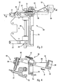
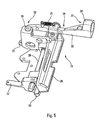
- Figures 3 and 5 are respectively plan and perspective of a locking device of a shutter system according to the invention.
- FIG. 4 is a section along the line IV-IV of FIG.
- FIG. 6 schematically shows, in partial longitudinal section, striker means of a closure system according to the invention.
- Figures 7 and 8 are perspective views of a hood according to the invention, shown respectively in profile and from above.
- the missile 1 comprises a body 3 containing, among other things, and usual expenses (which are not represented because they are not involved by the invention) and a fuel tank 4, intended for feeding the ramjet 2 and attached to the rear portion of said body 3.
- the ramjet 2 comprises a combustion chamber 5, terminating at the rear by an ejection nozzle 6 and connected, forwards, a plurality of air introduction ways, of the air-shaft type 7.
- the windsocks 7 are arranged at the periphery of the body 3 and are in solidarity with it. Each of them, towards the front, has an orifice 8 the air inlet and, towards the rear, opens into the front part of the combustion chamber 5 by an outlet 10 of air outlet of the sleeve 7.
- An elbow 11 is provided in each airfoil 7 to connect the part thereof attached to the outer wall of the body 3 to the orifice 10 corresponding to the inlet of the combustion chamber 5.
- a device 12 for fuel injection is provided in the vicinity of the front portion 9 of the combustion chamber 5 .
- the device 12 is controlled by a fuel supply and regulation device (not shown) carried by the body 3 and connected to the tank 4.
- a thermal protection coating 13 is provided on the walls internal combustion chamber 5.
- the operation of the missile 1 is as follows.
- the missile 1 is driven by a propellant consumable auxiliary 14 (for example a powder charge) housed at inside the combustion chamber 5.
- a propellant consumable auxiliary 14 for example a powder charge housed at inside the combustion chamber 5.
- the supply and regulating device feeds the fuel injection device 12 and the latter is ignited.
- the ramjet then enters into operation and takes over from the thruster 14 (which disappeared) to propel the missile 1.
- the locking device 19 comprises an unlocking mechanism 29 which includes a blade 30.
- This blade 30 is subjected to the action of a return spring 31 and is susceptible to be moved in the direction illustrated by an arrow B in FIG. act by one 32 of its ends on the clamping rod 26 to unlock it.
- Said blade 30 has at its other end 33 a trap 34 which is intended to cooperate with the striker means 21 of the actuating device 17.
- projection means 36 is made in the form of a pyrotechnic striker which has been partially shown a cord 37 making it possible to transmit the command (electric firing), to control the trigger said striker 36.
- Said striker means 21 further comprises a rectilinear guide 38 to guide the projectile 35, rectilinear guide which is made in the form of a channel 38, one end of which is opposite said projection means 36 and whose other end is directed towards the trap 34, which allows to optimize the accuracy of the projection and thus the effectiveness of the unlocking.
- said striker means act directly on the jaws 20 or via a mechanism different from that 26, 29 shown in Figures 3 to 5.
- said trap 34 also comprises an elastic buffer 39 shown in Figure 4, to dampen the shock during impact of the projectile 35 so as to obtain a "soft” impact, which makes it possible retain the corresponding momentum while protecting the trap 34, as well as the mechanical elements located near said trap 34.
- the hood 18, pyramidal shape has a face 40 which is inclined with respect to the flow E outside the missile 1. Thanks to the force exerted by this flow E on this face 40, the cover 18 is ejected off the sleeve to air 7, as soon as it is released from any mechanical stress on its face lower 18B, that is to say, as soon as the jaws 20 are unlocked.
- the shutter system 16 according to the invention and presented above works as follows.
- the shutter system 16 according to the invention is simple realization and operation and it is inexpensive and compact, especially in ramjet phase.
- the projectile 35 is not ejected (separately) out of the ramjet 2 when unlocking. Consequently, he there is no risk to the safety of persons or objects find in the near environment of the missile 1.
- said shutter system 16 according to the invention can be applied to other types of ducts, and not only to windsocks 7.
Landscapes
- Engineering & Computer Science (AREA)
- Chemical & Material Sciences (AREA)
- Combustion & Propulsion (AREA)
- Mechanical Engineering (AREA)
- General Engineering & Computer Science (AREA)
- Aiming, Guidance, Guns With A Light Source, Armor, Camouflage, And Targets (AREA)
- Portable Nailing Machines And Staplers (AREA)
- Exhaust Gas After Treatment (AREA)
- Compressor (AREA)
- Pipe Accessories (AREA)
- Lubrication Of Internal Combustion Engines (AREA)
- Testing Of Engines (AREA)
Claims (12)
- Verschlussvorrichtung für eine Öffnung (8) eines Rohres (7), die Folgendes aufweist:dadurch gekennzeichnet, dass der Verschluss (15) eine abnehmbare Abdeckung (18), die so auf dem Rohr (7) gehalten wird, dass sie die Öffnung (8) vollständig verschließt, und eine Verriegelungsvorrichtung (19), welche die Abdeckung (18) mit Hilfe von mindestens einer verriegelten Spannbacke (20), die entriegelbar ist, auf dem Rohr hält, aufweist, und dass die Betätigungsvorrichtung (17) mindestens ein steuerbares Schlagmittel (21) aufweist, das geeignet ist, die Spannbacke (20) zu entriegeln, so dass das Ausstoßen der Abdeckung (18) aus dem Rohr (7) herbeigeführt wird und die Öffnung (8) freigemacht wird.einen Verschluss (15), der geeignet ist, die Öffnung (8) des Rohres (7) vollständig zu verschließen; undeine steuerbare Betätigungsvorrichtung (17), die geeignet ist, auf den Verschluss (15) zu wirken, um die Öffnung (8) freizumachen,
- Verschlussvorrichtung nach Anspruch 1,
dadurch gekennzeichnet, dass das Schlagmittel (21) auf eine Auffangvorrichtung (34) wirkt, die unter der Wirkung des Schlagmittels (21) verschiebbar ist. - Verschlussvorrichtung nach Anspruch 2,
dadurch gekennzeichnet, dass die Auffangvorrichtung (34) einen elastischen Dämpfer (39) aufweist, um die Wirkung des Schlagmittels (21) zu dämpfen. - Verschlussvorrichtung nach einem der Ansprüche 1 bis 3,
dadurch gekennzeichnet, dass die Verriegelungsvorrichtung (19) mindestens eine Klemmvorrichtung (26) aufweist, die geeignet ist, die Spannbacke (20) so auf das Rohr (7) zu drücken, dass sie verriegelt wird, und die geeignet ist, so bewegt zu werden, dass die Spannbacke (20) entriegelt wird. - Verschlussvorrichtung nach einem der Ansprüche 1 bis 4,
dadurch gekennzeichnet, dass die Verriegelungsvorrichtung (19) mindestens eine Befestigung (22) in Form eines Bügels aufweist, die geeignet ist, in eine Halterung (23) in Form eines Hakens eingehängt zu werden, die an der Außenseite des Rohres (7) befestigt ist. - Verschlussvorrichtung nach einem der Ansprüche 2 und 3,
dadurch gekennzeichnet, dass das Schlagmittel (21) Folgendes umfasst:mindestens ein Projektil (35), das geeignet ist, die Auffangvorrichtung (34) zu bewegen, wenn es in sie hineingeschossen wird, undmindestens eine steuerbare Schussvorrichtung (36), die geeignet ist, das Projektil (35) abzuschießen, und die außerhalb des Rohres (7) angeordnet ist, wobei sie so ausgerichtet ist, dass sie das Projektil (35) in die Auffangvorrichtung (34) schießen kann. - Verschlussvorrichtung nach Anspruch 6,
dadurch gekennzeichnet, dass sie ferner eine geradlinige Führung (38) zum Lenken des Projektils (35) aufweist, die als Kanal (38) ausgebildet ist, dessen eines Ende sich gegenüber der Schussvorrichtung (36) befindet, und dessen anderes Ende zur Auffangvorrichtung (34) zeigt. - Verschlussvorrichtung nach einem der vorhergehenden Ansprüche,
dadurch gekennzeichnet, dass das Schlagmittel (21) einen pyrotechnischen Schlagbolzen (36) aufweist. - Verschlussvorrichtung nach einem der vorhergehenden Ansprüche,
dadurch gekennzeichnet, dass die Abdeckung (18) eine Außenseite (40) aufweist, die in Bezug zu einer vorbestimmten Richtung, die repräsentativ für einen Fluidstrom (E) außerhalb des Rohres (7) ist, schräg steht. - Verschlussvorrichtung nach einem der vorhergehenden Ansprüche für eine Öffnung (8) eines Luftzuführungsrohres (7),
dadurch gekennzeichnet, dass der Verschluss (15) die Eintrittsöffnung (8) in das Luftzuführungsrohr (7) vor dem Luftzuführungsrohr (7) in Richtung (F) des Luftstroms in dem Luftzuführungsrohr (7) verschließt. - Staustrahltriebwerk (2), das eine Verbrennungskammer (5), die mit mindestens einem Rohr (7) zum Zuführen von Verbrennungsluft in das Innere der Verbrennungskammer (5) ausgestattet ist, und eine Verschlussvorrichtung (16) für eine Öffnung (8) des Zuführungsrohres für Verbrennungsluft (7) aufweist, wobei die Verschlussvorrichtung (16) mindestens einen Verschluss (15), der geeignet ist, die Öffnung (8) in einer anfänglichen Betriebsphase im Raketenantriebsmodus vollständig zu verschließen, und mindestens eine steuerbare Betätigungsvorrichtung (17), die geeignet ist, so auf den Verschluss (15) zu wirken, dass dieser die Öffnung (8) für einen Betrieb im Staustrahlantriebsmodus öffnet, aufweist, wobei das Staustrahltriebwerk (2) geeignet ist, in der anfänglichen Betriebsphase, die der Phase entspricht, in der das Staustrahltriebwerk auf eine gewisse Geschwindigkeit gebracht wird, dank einer verbrennbaren Zusatztreibladung (14), die in der Verbrennungskammer (5) angeordnet ist, im Raketenantriebsmodus zu arbeiten, und dann, wenn das Staustrahltriebwerk (2) eine vorbestimmte Geschwindigkeit erreicht, im eigentlichen Staustrahlantriebsmodus zu arbeiten, bei dem Brennstoff und Verbrennungsluft in die Verbrennungskammer (5) eingespritzt werden,
dadurch gekennzeichnet, dass die Verschlussvorrichtung (16) so ausgeführt ist, wie sie unter einem der Ansprüche 1 bis 10 beschrieben wird. - Flugkörper,
dadurch gekennzeichnet, dass er ein Staustrahltriebwerk (2) nach Anspruch 11 aufweist.
Applications Claiming Priority (2)
| Application Number | Priority Date | Filing Date | Title |
|---|---|---|---|
| FR0100383A FR2819556B1 (fr) | 2001-01-12 | 2001-01-12 | Systeme d'obturation pour un orifice d'un conduit, en particulier pour un orifice d'une voie d'introduction d'air dans la chambre de combustion d'un statoreacteur |
| FR0100383 | 2001-01-12 |
Publications (2)
| Publication Number | Publication Date |
|---|---|
| EP1225326A1 EP1225326A1 (de) | 2002-07-24 |
| EP1225326B1 true EP1225326B1 (de) | 2005-10-05 |
Family
ID=8858739
Family Applications (1)
| Application Number | Title | Priority Date | Filing Date |
|---|---|---|---|
| EP02290020A Expired - Lifetime EP1225326B1 (de) | 2001-01-12 | 2002-01-07 | Rohrverschlussvorrichtung, insbesondere für Luftrohre in einem Staustrahlantrieb |
Country Status (8)
| Country | Link |
|---|---|
| US (1) | US6725664B2 (de) |
| EP (1) | EP1225326B1 (de) |
| AT (1) | ATE306017T1 (de) |
| CA (1) | CA2366044C (de) |
| DE (1) | DE60206424T2 (de) |
| ES (1) | ES2250595T3 (de) |
| FR (1) | FR2819556B1 (de) |
| RU (1) | RU2219362C2 (de) |
Families Citing this family (10)
| Publication number | Priority date | Publication date | Assignee | Title |
|---|---|---|---|---|
| FR2840029B1 (fr) * | 2002-05-27 | 2004-08-13 | Mbdam | Systeme d'obturation pour un orifice d'un conduit, en particulier pour un orifice d'une voie d'introduction d'air dans la chambre de combustion d'un statoreacteur |
| RU2413860C2 (ru) * | 2009-01-11 | 2011-03-10 | Владимир Анатольевич Коликов | Способ создания импульса силы и устройство для его реализации |
| US9032737B2 (en) | 2009-12-30 | 2015-05-19 | Rolls-Royce North American Technologies, Inc. | Combustor added to a gas turbine engine to increase thrust |
| RU2739449C1 (ru) * | 2019-10-31 | 2020-12-24 | Акционерное Общество "Государственное Машиностроительное Конструкторское Бюро "Радуга" Имени А.Я. Березняка" | Воздухозаборное устройство со сбрасываемой заглушкой беспилотного летательного аппарата с воздушно-реактивным двигателем |
| RU197363U1 (ru) * | 2019-11-13 | 2020-04-23 | Акционерное Общество "Государственное Машиностроительное Конструкторское Бюро "Радуга" Имени А.Я. Березняка" | Сбрасываемый пиропривод с заглушкой для воздухозаборных устройств беспилотных летательных аппаратов с воздушно-реактивным двигателем |
| KR102940704B1 (ko) | 2020-05-05 | 2026-03-18 | 아틀란티스 리서치 랩스 인크. | 멀티 모드 추진 시스템 |
| CN111948334B (zh) * | 2020-07-20 | 2022-07-15 | 西安近代化学研究所 | 一种推进剂燃烧速度测试装置 |
| CN112627983B (zh) * | 2020-12-25 | 2022-02-22 | 中国人民解放军国防科技大学 | 一种rbcc发动机内流道及rbcc发动机 |
| CN113202655B (zh) * | 2021-06-07 | 2022-05-24 | 北京理工大学 | 一种固液冲压组合发动机 |
| CN115107968B (zh) * | 2022-06-13 | 2023-04-18 | 南昌航空大学 | 一种低航速水下冲压发动机及其设计方法 |
Family Cites Families (25)
| Publication number | Priority date | Publication date | Assignee | Title |
|---|---|---|---|---|
| US3038303A (en) * | 1958-01-02 | 1962-06-12 | Robert O Gose | Thrust termination in solid propellant rockets |
| US3137408A (en) * | 1962-07-09 | 1964-06-16 | Rubbermaid Inc | Pail with lid and latching mechanism |
| US3768255A (en) * | 1967-03-06 | 1973-10-30 | Texaco Inc | Inlet port covers for reaction vehicle |
| DE1626069B1 (de) * | 1967-10-18 | 1970-10-08 | Messerschmitt Boelkow Blohm | Kombinationstriebwerk |
| US3901028A (en) * | 1972-09-13 | 1975-08-26 | Us Air Force | Ramjet with integrated rocket boost motor |
| US4028886A (en) * | 1975-10-23 | 1977-06-14 | Mcdonnell Douglas Corporation | Passive chamber wall fragmenter |
| US4022352A (en) * | 1976-04-26 | 1977-05-10 | Pehr Harold T | Container cover and safety closure |
| US4047495A (en) * | 1976-05-03 | 1977-09-13 | Polytop Corporation | Child resistant dispensing closures |
| US4441312A (en) * | 1979-06-22 | 1984-04-10 | The United States Of America As Represented By The Secretary Of The Air Force | Combined cycle ramjet engine |
| DE3003004C2 (de) | 1980-01-29 | 1982-06-03 | Messerschmitt-Bölkow-Blohm GmbH, 8000 München | Deckel aus leicht zerstörbarem Material zum Verschließen der in die Brennkammer von kombinierten Staustrahl-Raketentriebwerken einmündenden Lufteinlauföffnungen, und Schlagvorrichtung zum Zerstören des Deckels |
| DE3242585C2 (de) * | 1982-11-18 | 1985-01-10 | Messerschmitt-Bölkow-Blohm GmbH, 8000 München | Verschlußeinrichtung für einen in die Brennkammer von Staustrahl-Raketentriebwerken einmündenden Lufteinlaufkanal |
| FR2629136B1 (fr) * | 1985-09-17 | 1990-11-09 | Aerospatiale | Statoreacteur pourvu d'une pluralite de manches d'alimentation en air carbure et missile pourvu d'un tel statoreacteur |
| FR2591664B1 (fr) * | 1985-12-13 | 1988-03-25 | Aerospatiale | Systeme d'injection de carburant pour statoreacteur, statoreacteur pourvu d'un tel systeme d'injection et missile propulse par ce statoreacteur |
| DE3738703A1 (de) * | 1987-05-27 | 1988-12-08 | Mtu Muenchen Gmbh | Kombiniertes, umschaltbares strahltriebwerk zum antrieb von flugzeugen und raumfahrzeugen |
| US4865267A (en) * | 1988-02-25 | 1989-09-12 | Sundstrand Corporation | Ram air flow system for aircraft |
| JPH079216B2 (ja) | 1989-07-24 | 1995-02-01 | 防衛庁技術研究本部長 | ラムロケット |
| JP3057867B2 (ja) | 1991-12-06 | 2000-07-04 | 石川島播磨重工業株式会社 | 圧延機用スピンドル |
| US6003302A (en) * | 1996-05-10 | 1999-12-21 | Feldman; Peter | Ramjet with adjustable working duct casings |
| FR2755182B1 (fr) * | 1996-10-30 | 1998-12-31 | Aerospatiale | Systeme d'obturation pour un orifice d'entree d'air dans la chambre de combustion d'un statoreacteur |
| US5784877A (en) * | 1996-11-08 | 1998-07-28 | Atlantic Research Corporation | Rocket-ramjet engine casing port closure |
| JPH10314027A (ja) * | 1997-05-19 | 1998-12-02 | P-Kotsuku Mahobin Kogyo Kk | 容器の蓋取付け構造 |
| US6058846A (en) * | 1998-06-03 | 2000-05-09 | Lockhead Martin Corporation | Rocket and ramjet powered hypersonic stealth missile having alterable radar cross section |
| FR2810642B1 (fr) * | 2000-06-26 | 2003-02-07 | Seb Sa | Dispositif de verrouillage de couvercle |
| US6568554B2 (en) * | 2000-07-21 | 2003-05-27 | H-Tech, Inc. | Hydraulic or pneumatic safety device for fluid handling apparatus |
| FR2813344B1 (fr) * | 2000-08-28 | 2002-11-29 | Aerospatiale Matra Missiles | Systeme d'obturation pour un orifice d'un conduit, en particulier pour un orifice d'une voie d'introduction d'air dans la chambre de combustion d'un statoreacteur |
-
2001
- 2001-01-12 FR FR0100383A patent/FR2819556B1/fr not_active Expired - Lifetime
-
2002
- 2002-01-07 ES ES02290020T patent/ES2250595T3/es not_active Expired - Lifetime
- 2002-01-07 DE DE60206424T patent/DE60206424T2/de not_active Expired - Lifetime
- 2002-01-07 EP EP02290020A patent/EP1225326B1/de not_active Expired - Lifetime
- 2002-01-07 AT AT02290020T patent/ATE306017T1/de not_active IP Right Cessation
- 2002-01-10 US US10/041,670 patent/US6725664B2/en not_active Expired - Lifetime
- 2002-01-11 RU RU2002101495/06A patent/RU2219362C2/ru not_active IP Right Cessation
- 2002-01-11 CA CA002366044A patent/CA2366044C/fr not_active Expired - Lifetime
Also Published As
| Publication number | Publication date |
|---|---|
| ATE306017T1 (de) | 2005-10-15 |
| DE60206424T2 (de) | 2006-06-14 |
| FR2819556B1 (fr) | 2003-04-04 |
| CA2366044A1 (fr) | 2002-07-12 |
| CA2366044C (fr) | 2008-10-07 |
| DE60206424D1 (de) | 2005-11-10 |
| EP1225326A1 (de) | 2002-07-24 |
| FR2819556A1 (fr) | 2002-07-19 |
| ES2250595T3 (es) | 2006-04-16 |
| RU2219362C2 (ru) | 2003-12-20 |
| US20040050062A1 (en) | 2004-03-18 |
| US6725664B2 (en) | 2004-04-27 |
Similar Documents
| Publication | Publication Date | Title |
|---|---|---|
| EP1367251B1 (de) | Verschlusssystem für eine Öffnung einer Lufteinlassleitung einer Brennkammer eines Staustrahltriebwerks, sowie Staustrahltriebwerk und Flugkörper mit einem solchen System | |
| EP1225326B1 (de) | Rohrverschlussvorrichtung, insbesondere für Luftrohre in einem Staustrahlantrieb | |
| CA2356308C (fr) | Systeme d'obturation pour un orifice d'un conduit, en particulier pour un orifice d'une voie d'introduction d'air dans la chambre de combustion d'un statoreacteur | |
| EP2143927B1 (de) | Raketentriebwerk für Flüssigtreibstoff mit Verschlussblende zur Brennkammer | |
| WO2016193641A1 (fr) | Dispositif de verrouillage de capots pivotants d'un inverseur de poussée | |
| FR2482665A1 (fr) | Moteur-fusee a carburant solide et a poussee variable | |
| EP0839999B1 (de) | Einrichtung zur Beseitigung des Verschlusses der in die Brennkammer von Staustrahltriebwerken einmündenden Lufteinlaufkanäle | |
| EP3195983B1 (de) | Gasfixierungswerkzeug und sein betätigungsverfahren | |
| FR2640369A1 (fr) | Projectile de lancement de leurres electromagnetiques | |
| EP2530425B1 (de) | Unterwassergerät, das Mittel zum Aussetzen eines Unterwasserfahrzeugs umfasst | |
| FR2858662A1 (fr) | Appareil de combustion a propergol solide | |
| FR2705739A1 (fr) | Tuyère de moteur-fusée à section de sortie sélectivement réduite. | |
| FR2976065A1 (fr) | Engin sous-marin comportant des moyens de lancement d'un vehicule sous-marin en auto-demarrage | |
| EP4025782A1 (de) | Schubumkehrvorrichtung mit seilkinematik für schaufelklappen | |
| FR2535045A1 (fr) | Projectile declencheur d'avalanches | |
| FR2847306A1 (fr) | Entree d'air pour propulseur et sa fabrication | |
| FR2530332A1 (fr) | Dispositif d'ouverture de l'empennage d'un projectile | |
| FR2930817A1 (fr) | Systeme d'obturation d'un conduit d'evacuation des gaz d'un lanceur de missiles | |
| EP2623918B1 (de) | Pneumatische abschussvorrichtung | |
| EP3891375B1 (de) | Festkörper-booster für eine abschussvorrichtung | |
| FR2652641A1 (fr) | Dispositif pour le freinage d'une bombe apres son largage d'un aeronef. | |
| FR2655723A1 (fr) | Dispositif d'obturation d'une tuyere pour un generateur de gaz equipant un engin volant. | |
| FR2986610A1 (fr) | Dispositif de detente rapide pour dispositif de lancement pneumatique | |
| FR3035922A1 (fr) | Dispositif d'inversion de poussee pour un turboreacteur d'aeronef, et nacelle comportant le dispositif |
Legal Events
| Date | Code | Title | Description |
|---|---|---|---|
| PUAI | Public reference made under article 153(3) epc to a published international application that has entered the european phase |
Free format text: ORIGINAL CODE: 0009012 |
|
| AK | Designated contracting states |
Kind code of ref document: A1 Designated state(s): AT BE CH CY DE DK ES FI FR GB GR IE IT LI LU MC NL PT SE TR |
|
| AX | Request for extension of the european patent |
Free format text: AL;LT;LV;MK;RO;SI |
|
| 17P | Request for examination filed |
Effective date: 20020812 |
|
| AKX | Designation fees paid |
Designated state(s): AT BE CH CY DE DK ES FI FR GB GR IE IT LI LU MC NL PT SE TR |
|
| 17Q | First examination report despatched |
Effective date: 20050113 |
|
| GRAP | Despatch of communication of intention to grant a patent |
Free format text: ORIGINAL CODE: EPIDOSNIGR1 |
|
| GRAS | Grant fee paid |
Free format text: ORIGINAL CODE: EPIDOSNIGR3 |
|
| GRAA | (expected) grant |
Free format text: ORIGINAL CODE: 0009210 |
|
| AK | Designated contracting states |
Kind code of ref document: B1 Designated state(s): AT BE CH CY DE DK ES FI FR GB GR IE IT LI LU MC NL PT SE TR |
|
| PG25 | Lapsed in a contracting state [announced via postgrant information from national office to epo] |
Ref country code: IE Free format text: LAPSE BECAUSE OF FAILURE TO SUBMIT A TRANSLATION OF THE DESCRIPTION OR TO PAY THE FEE WITHIN THE PRESCRIBED TIME-LIMIT Effective date: 20051005 Ref country code: FI Free format text: LAPSE BECAUSE OF FAILURE TO SUBMIT A TRANSLATION OF THE DESCRIPTION OR TO PAY THE FEE WITHIN THE PRESCRIBED TIME-LIMIT Effective date: 20051005 Ref country code: AT Free format text: LAPSE BECAUSE OF FAILURE TO SUBMIT A TRANSLATION OF THE DESCRIPTION OR TO PAY THE FEE WITHIN THE PRESCRIBED TIME-LIMIT Effective date: 20051005 |
|
| REG | Reference to a national code |
Ref country code: GB Ref legal event code: FG4D Free format text: NOT ENGLISH |
|
| REG | Reference to a national code |
Ref country code: CH Ref legal event code: EP |
|
| GBT | Gb: translation of ep patent filed (gb section 77(6)(a)/1977) |
Effective date: 20051005 |
|
| REG | Reference to a national code |
Ref country code: IE Ref legal event code: FG4D Free format text: LANGUAGE OF EP DOCUMENT: FRENCH |
|
| REF | Corresponds to: |
Ref document number: 60206424 Country of ref document: DE Date of ref document: 20051110 Kind code of ref document: P |
|
| PG25 | Lapsed in a contracting state [announced via postgrant information from national office to epo] |
Ref country code: GR Free format text: LAPSE BECAUSE OF FAILURE TO SUBMIT A TRANSLATION OF THE DESCRIPTION OR TO PAY THE FEE WITHIN THE PRESCRIBED TIME-LIMIT Effective date: 20060105 Ref country code: DK Free format text: LAPSE BECAUSE OF FAILURE TO SUBMIT A TRANSLATION OF THE DESCRIPTION OR TO PAY THE FEE WITHIN THE PRESCRIBED TIME-LIMIT Effective date: 20060105 |
|
| REG | Reference to a national code |
Ref country code: SE Ref legal event code: TRGR |
|
| PG25 | Lapsed in a contracting state [announced via postgrant information from national office to epo] |
Ref country code: MC Free format text: LAPSE BECAUSE OF NON-PAYMENT OF DUE FEES Effective date: 20060131 Ref country code: LU Free format text: LAPSE BECAUSE OF NON-PAYMENT OF DUE FEES Effective date: 20060131 Ref country code: LI Free format text: LAPSE BECAUSE OF NON-PAYMENT OF DUE FEES Effective date: 20060131 Ref country code: FR Free format text: LAPSE BECAUSE OF NON-PAYMENT OF DUE FEES Effective date: 20060131 Ref country code: CH Free format text: LAPSE BECAUSE OF NON-PAYMENT OF DUE FEES Effective date: 20060131 |
|
| PG25 | Lapsed in a contracting state [announced via postgrant information from national office to epo] |
Ref country code: PT Free format text: LAPSE BECAUSE OF FAILURE TO SUBMIT A TRANSLATION OF THE DESCRIPTION OR TO PAY THE FEE WITHIN THE PRESCRIBED TIME-LIMIT Effective date: 20060306 |
|
| REG | Reference to a national code |
Ref country code: ES Ref legal event code: FG2A Ref document number: 2250595 Country of ref document: ES Kind code of ref document: T3 |
|
| REG | Reference to a national code |
Ref country code: IE Ref legal event code: FD4D |
|
| PLBE | No opposition filed within time limit |
Free format text: ORIGINAL CODE: 0009261 |
|
| STAA | Information on the status of an ep patent application or granted ep patent |
Free format text: STATUS: NO OPPOSITION FILED WITHIN TIME LIMIT |
|
| 26N | No opposition filed |
Effective date: 20060706 |
|
| REG | Reference to a national code |
Ref country code: CH Ref legal event code: PL |
|
| REG | Reference to a national code |
Ref country code: FR Ref legal event code: ST Effective date: 20060929 |
|
| PG25 | Lapsed in a contracting state [announced via postgrant information from national office to epo] |
Ref country code: TR Free format text: LAPSE BECAUSE OF FAILURE TO SUBMIT A TRANSLATION OF THE DESCRIPTION OR TO PAY THE FEE WITHIN THE PRESCRIBED TIME-LIMIT Effective date: 20051005 |
|
| PG25 | Lapsed in a contracting state [announced via postgrant information from national office to epo] |
Ref country code: CY Free format text: LAPSE BECAUSE OF FAILURE TO SUBMIT A TRANSLATION OF THE DESCRIPTION OR TO PAY THE FEE WITHIN THE PRESCRIBED TIME-LIMIT Effective date: 20051005 |
|
| GBPC | Gb: european patent ceased through non-payment of renewal fee |
Effective date: 20100107 |
|
| PG25 | Lapsed in a contracting state [announced via postgrant information from national office to epo] |
Ref country code: GB Free format text: LAPSE BECAUSE OF NON-PAYMENT OF DUE FEES Effective date: 20100107 |
|
| REG | Reference to a national code |
Ref country code: GB Ref legal event code: S28 Free format text: APPLICATION FILED |
|
| REG | Reference to a national code |
Ref country code: GB Ref legal event code: S28 Free format text: RESTORATION ALLOWED Effective date: 20110629 |
|
| PGFP | Annual fee paid to national office [announced via postgrant information from national office to epo] |
Ref country code: NL Payment date: 20191217 Year of fee payment: 19 |
|
| PGFP | Annual fee paid to national office [announced via postgrant information from national office to epo] |
Ref country code: DE Payment date: 20200113 Year of fee payment: 19 Ref country code: IT Payment date: 20200113 Year of fee payment: 19 Ref country code: SE Payment date: 20200115 Year of fee payment: 19 Ref country code: GB Payment date: 20200131 Year of fee payment: 19 Ref country code: ES Payment date: 20200227 Year of fee payment: 19 |
|
| PGFP | Annual fee paid to national office [announced via postgrant information from national office to epo] |
Ref country code: BE Payment date: 20200127 Year of fee payment: 19 |
|
| REG | Reference to a national code |
Ref country code: DE Ref legal event code: R119 Ref document number: 60206424 Country of ref document: DE |
|
| REG | Reference to a national code |
Ref country code: SE Ref legal event code: EUG |
|
| REG | Reference to a national code |
Ref country code: NL Ref legal event code: MM Effective date: 20210201 |
|
| GBPC | Gb: european patent ceased through non-payment of renewal fee |
Effective date: 20210107 |
|
| REG | Reference to a national code |
Ref country code: BE Ref legal event code: MM Effective date: 20210131 |
|
| PG25 | Lapsed in a contracting state [announced via postgrant information from national office to epo] |
Ref country code: NL Free format text: LAPSE BECAUSE OF NON-PAYMENT OF DUE FEES Effective date: 20210201 |
|
| PG25 | Lapsed in a contracting state [announced via postgrant information from national office to epo] |
Ref country code: DE Free format text: LAPSE BECAUSE OF NON-PAYMENT OF DUE FEES Effective date: 20210803 Ref country code: GB Free format text: LAPSE BECAUSE OF NON-PAYMENT OF DUE FEES Effective date: 20210107 Ref country code: SE Free format text: LAPSE BECAUSE OF NON-PAYMENT OF DUE FEES Effective date: 20210108 |
|
| REG | Reference to a national code |
Ref country code: ES Ref legal event code: FD2A Effective date: 20220413 |
|
| PG25 | Lapsed in a contracting state [announced via postgrant information from national office to epo] |
Ref country code: IT Free format text: LAPSE BECAUSE OF NON-PAYMENT OF DUE FEES Effective date: 20210107 |
|
| PG25 | Lapsed in a contracting state [announced via postgrant information from national office to epo] |
Ref country code: ES Free format text: LAPSE BECAUSE OF NON-PAYMENT OF DUE FEES Effective date: 20210108 Ref country code: BE Free format text: LAPSE BECAUSE OF NON-PAYMENT OF DUE FEES Effective date: 20210131 |