EP1225657A2 - Verbindung für Erdungsstromschiene - Google Patents
Verbindung für Erdungsstromschiene Download PDFInfo
- Publication number
- EP1225657A2 EP1225657A2 EP02250385A EP02250385A EP1225657A2 EP 1225657 A2 EP1225657 A2 EP 1225657A2 EP 02250385 A EP02250385 A EP 02250385A EP 02250385 A EP02250385 A EP 02250385A EP 1225657 A2 EP1225657 A2 EP 1225657A2
- Authority
- EP
- European Patent Office
- Prior art keywords
- bus bar
- pair
- conductor
- connector
- slot
- Prior art date
- Legal status (The legal status is an assumption and is not a legal conclusion. Google has not performed a legal analysis and makes no representation as to the accuracy of the status listed.)
- Withdrawn
Links
Images


Classifications
-
- H—ELECTRICITY
- H01—ELECTRIC ELEMENTS
- H01R—ELECTRICALLY-CONDUCTIVE CONNECTIONS; STRUCTURAL ASSOCIATIONS OF A PLURALITY OF MUTUALLY-INSULATED ELECTRICAL CONNECTING ELEMENTS; COUPLING DEVICES; CURRENT COLLECTORS
- H01R4/00—Electrically-conductive connections between two or more conductive members in direct contact, i.e. touching one another; Means for effecting or maintaining such contact; Electrically-conductive connections having two or more spaced connecting locations for conductors and using contact members penetrating insulation
- H01R4/58—Electrically-conductive connections between two or more conductive members in direct contact, i.e. touching one another; Means for effecting or maintaining such contact; Electrically-conductive connections having two or more spaced connecting locations for conductors and using contact members penetrating insulation characterised by the form or material of the contacting members
- H01R4/60—Connections between or with tubular conductors
-
- H—ELECTRICITY
- H01—ELECTRIC ELEMENTS
- H01R—ELECTRICALLY-CONDUCTIVE CONNECTIONS; STRUCTURAL ASSOCIATIONS OF A PLURALITY OF MUTUALLY-INSULATED ELECTRICAL CONNECTING ELEMENTS; COUPLING DEVICES; CURRENT COLLECTORS
- H01R4/00—Electrically-conductive connections between two or more conductive members in direct contact, i.e. touching one another; Means for effecting or maintaining such contact; Electrically-conductive connections having two or more spaced connecting locations for conductors and using contact members penetrating insulation
- H01R4/10—Electrically-conductive connections between two or more conductive members in direct contact, i.e. touching one another; Means for effecting or maintaining such contact; Electrically-conductive connections having two or more spaced connecting locations for conductors and using contact members penetrating insulation effected solely by twisting, wrapping, bending, crimping, or other permanent deformation
- H01R4/18—Electrically-conductive connections between two or more conductive members in direct contact, i.e. touching one another; Means for effecting or maintaining such contact; Electrically-conductive connections having two or more spaced connecting locations for conductors and using contact members penetrating insulation effected solely by twisting, wrapping, bending, crimping, or other permanent deformation by crimping
- H01R4/183—Electrically-conductive connections between two or more conductive members in direct contact, i.e. touching one another; Means for effecting or maintaining such contact; Electrically-conductive connections having two or more spaced connecting locations for conductors and using contact members penetrating insulation effected solely by twisting, wrapping, bending, crimping, or other permanent deformation by crimping for cylindrical elongated bodies, e.g. cables having circular cross-section
- H01R4/186—Electrically-conductive connections between two or more conductive members in direct contact, i.e. touching one another; Means for effecting or maintaining such contact; Electrically-conductive connections having two or more spaced connecting locations for conductors and using contact members penetrating insulation effected solely by twisting, wrapping, bending, crimping, or other permanent deformation by crimping for cylindrical elongated bodies, e.g. cables having circular cross-section using a body comprising a plurality of cable-accommodating recesses or bores
-
- H—ELECTRICITY
- H01—ELECTRIC ELEMENTS
- H01R—ELECTRICALLY-CONDUCTIVE CONNECTIONS; STRUCTURAL ASSOCIATIONS OF A PLURALITY OF MUTUALLY-INSULATED ELECTRICAL CONNECTING ELEMENTS; COUPLING DEVICES; CURRENT COLLECTORS
- H01R4/00—Electrically-conductive connections between two or more conductive members in direct contact, i.e. touching one another; Means for effecting or maintaining such contact; Electrically-conductive connections having two or more spaced connecting locations for conductors and using contact members penetrating insulation
- H01R4/58—Electrically-conductive connections between two or more conductive members in direct contact, i.e. touching one another; Means for effecting or maintaining such contact; Electrically-conductive connections having two or more spaced connecting locations for conductors and using contact members penetrating insulation characterised by the form or material of the contacting members
- H01R4/64—Connections between or with conductive parts having primarily a non-electric function, e.g. frame, casing, rail
-
- H—ELECTRICITY
- H01—ELECTRIC ELEMENTS
- H01R—ELECTRICALLY-CONDUCTIVE CONNECTIONS; STRUCTURAL ASSOCIATIONS OF A PLURALITY OF MUTUALLY-INSULATED ELECTRICAL CONNECTING ELEMENTS; COUPLING DEVICES; CURRENT COLLECTORS
- H01R4/00—Electrically-conductive connections between two or more conductive members in direct contact, i.e. touching one another; Means for effecting or maintaining such contact; Electrically-conductive connections having two or more spaced connecting locations for conductors and using contact members penetrating insulation
- H01R4/26—Connections in which at least one of the connecting parts has projections which bite into or engage the other connecting part in order to improve the contact
-
- H—ELECTRICITY
- H01—ELECTRIC ELEMENTS
- H01R—ELECTRICALLY-CONDUCTIVE CONNECTIONS; STRUCTURAL ASSOCIATIONS OF A PLURALITY OF MUTUALLY-INSULATED ELECTRICAL CONNECTING ELEMENTS; COUPLING DEVICES; CURRENT COLLECTORS
- H01R4/00—Electrically-conductive connections between two or more conductive members in direct contact, i.e. touching one another; Means for effecting or maintaining such contact; Electrically-conductive connections having two or more spaced connecting locations for conductors and using contact members penetrating insulation
- H01R4/28—Clamped connections, spring connections
- H01R4/50—Clamped connections, spring connections utilising a cam, wedge, cone or ball also combined with a screw
- H01R4/505—Clamped connections, spring connections utilising a cam, wedge, cone or ball also combined with a screw using an excentric element
Definitions
- the present invention relates generally to a connector for attachment to a ground bus bar. More particularly, the present invention relates to a connector for providing quick and secure connection between a plurality of electrical conductors and a ground bus bar.
- One embodiment shown in the '368 patent includes a generally U-shaped connector where the bus bar is received in the space between the legs of the U-shaped body. At the upper end of the U-shaped legs, channels are formed for accommodating a ground conductor. The conductors are connected in the channels and the connector is attached to the bus bar. The connector is crimped in a subtle crimped tool to effect connection between the conductor and the bus bar.
- the present invention discloses a ground connector, for providing a quick, secure and permanent connection between a plurality of conductors and a ground bus bar.
- the ground conductors are crimped first in the tool before the connector is slipped over the bus bar, thereby establishing electrical and mechanical connection there between.
- a ground connector having a deformable generally U-Shaped conductive body including a pair of legs projecting from the body.
- the legs define an open ended slot for receiving a bus bar therein for crimp connection.
- a plurality of teeth on at least one of the legs project into the slot to establish an electrical connection between the bus bar and the body.
- the body has at least one aperture to receive at least one conductor therein so that when the body is deformed to crimp the bus bar in the slot, the conductor is crimped within the aperture to the body.
- a ground connector having a generally U-Shaped body of deformably conductive material including a pair of open ended slots.
- Each of the slots are defined by opposed, spaced sidewalls and a closed end, and are configured to receive a respective bus bar therein through the open end.
- a plurality of teeth extend on each of the side walls of the slots to establish an electrical crimp connection between the respective bus bars and the body.
- the body includes a plurality of apertures extending through the body, where at least one of the apertures is located on opposite sides of at least one of the slots to respectively receive at least one conductor therein, so that when the body is deformed to crimp the bus bars in the slots, the conductors are crimped within the apertures to the body
- a ground connector having a conductive deformable body including a pair of legs at opposite ends of the body defining a generally U-shaped configuration.
- the body has an open ended slot defined by a lower end and opposed side walls extending upwardly from a center portion of the body on each leg, the slot being adapted to receive a bus bar for electrical crimp connection.
- a plurality of inwardly teeth extend from each of the side walls into the slot to establish an electrical crimp connection between the bus bar and the body.
- the body at the lower end of the open ended slot has a pair of spaced apart outwardly angled cut outs to allow the body to deform into a secure crimp connection to the bus bar.
- a pair of spaced apertures each of the aperture being adapted to receive at least one conductor therein, so that when the opposite ends of the body are deformed to crimp the bus bar, the conductors are crimped to the body.
- a method for crimping a connector to at least one bus bar and at least one conductor includes providing a connector including a deformable body having a pair of legs defining a central opening, where each leg has teeth extending into the opening, the body has at least one channel extending through, and the channel is adapted to receive a conductor therein; placing at least one conductor in the channel; deforming the body to initiate a partial crimp between the body and the conductor placed in the channel; inserting a bus bar into the central opening of the body after the conductor is partially crimped and continuing to deform the connector until the conductors are tightly crimped within the channels in the body and the bus bar is crimped between the legs.
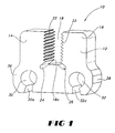
- Bus bar connector 10 includes a generally flat planar body 12, formed of malleable electrical conducting metal, preferably copper.
- the body may be considered to be U-shaped, having a pair of legs 14 and 16 and a central upwardly extending, open ended slot 18.
- Slot 18 accommodates a rectangular bus bar (not shown) for electrical crimp connection thereto.
- the body includes a plurality of inwardly directed teeth 22, defining the perimeter of the slot 18. The teeth 22 help engage the bus bar by aggressively biting into the bus bar, penetrating any coating thereon to establish engagement therewith, increasing the electrical and mechanical performance.
- the slot 18 opens up in a scissors like fashion to allow for easy slippage over the bus bar, not shown, where the connector, 10 is fully crimped over the bus bar.
- the lower end 18a of slot 18 further includes a pair of outwardly angled cut outs 24 and 26.
- the cut outs 24 and 26 are provided by way of relief to help deform the legs 14 and 16 of the body during crimping to provide secure crimp connection to the bus bar. Also, the cut outs 24 and 26 in the slot 18 reduce the force required to crimp the body 12 to its proper configuration while making the installation easier for the user.
- Body 10 includes a pair of conductor receiving apertures or channels 30 and 32 spaced at apart locations opposite legs 12 and 14.
- Channels 30 and 32 are generally cylindrical so as to accommodate a cylindrical ground wire (not shown), freeing the installer's hand to operate the tool.
- Each channel 30 and 32 include an access openings 30a and 32a respectively in communication therewith, extending through the lower surface of the body. The access openings provide an area of relief which accommodates the crimp connection of the body around the conductors.
- body 12 includes a pair of outwardly directed shoulders 36 and 38, which provide a wider dimension in body 12 at the lower end thereof.
- bus bar connector of the present invention is shown in Figure 1.
- Alternative embodiments of the bus bar connector is shown with respect to Figures 2 and 3, where like reference numerals denote like components.
- Bus bar connector 10' shown in Figure 2, is substantially similar to bus bar connector 10 of Figure 1.
- Bus bar connector 10' includes a secondary slot 28' formed in body 12', extending inwardly from a lower surface thereof. Slot 28' may be used to accommodate, in an alternate fashion, a bus bar from the opposed lower end of body 12'. Slot 28' may include inwardly directed teeth 34' which are substantially similar to teeth 22' shown in upper slot 18'. The lower slot 28' also provides an area of relief to facilitate crimping of the connector.
- the conductor receiving apertures or channels 30' and 32' may include modifications to the access openings 30a' and 32a'.
- the access openings may include inwardly facing recesses 30b' and 32b' which may additionally accommodate a smaller gauge ground conductor for crimp connection with connector 10'.
- bus bar connector 10 is substantially similar to bus bar connector 10 of Figure 1.
- the lower end of slot 18" includes a centrally located cut out 25" which also provides additional relief to help deform the legs of body 12" during crimping. It is additionally contemplated that an additional ground conductor may be inserted in cut out 25" for crimp connection to connector 10". Also shown in Figure 3 is an alternate configuration for conductor receiving channel 32".
- the alternate embodiments of the connector shown in Figures 2 and 3 provide a body having alternate grooves, slots, holes of any shape and size possible, to accommodate more than two ground conductors of various ranges, simultaneously.
- Figures 4 - 7 show the progressive steps of crimping a pair of conductors to a bus bar, employing a bus bar connector of the present invention.
- Connector 110 includes a connector body 112, having a pair of legs 114 and 116, separated by a central slot 118.
- Bus bar 100 is shown inserted in the slot 118.
- the body includes a pair of channels 130 and 132 for accommodating conductors 102 and 104. The channels are accessible through access openings 130a and 132a.
- the connector body 112 may be positioned between a pair of spaced apart dies 150 and 152 of a crimping tool 160. When so positioned, the conductors 102 and 104 may be inserted into channels 130 and 132. While bus bar 100 is shown positioned within slot 118, at this stage of crimping it need not be positioned therein.
- Dies 150 and 152 are shown to have partially moved toward each opposite end of the connector 110. This partial movement of the dies causes the connector 110 to deform by engagement of the dies 150 and 152 by the shoulders 136 and 138 thereof. This partial movement begins the crimping process which partially crimps the conductors 102 and 104 therein. Slot 118 slightly opens during the initial crimping process, allowing the bus bar 100 to be subsequently placed therein.
- Figure 6 shows continued crimping of connector 110 by movement of dies 150 and 152. Continued crimping flattens the shoulders 136 and 138, causing the remainder of connector 110 to be deformed. Such deformation slightly crimps the conductors 102 and 104 in the connector while crimping the bus bar between the legs 114 and 116.
- Figure 7 shows the fully crimped connector 110 where the conductors 102 and 104 are tightly crimped within channels 130 and 132.
- the slots 130a and 132a have almost completely closed, providing a tight crimped connection with connector body 112.
- the legs 114 and 116 are crimp connected to the bus bar 100, at slot 118, providing electrical and mechanical engagement there between.
- the location and arrangement of the conductor receiving channels 130 and 132 as well as the slot 118 allows for ease of installation and crimping.
- the conductors 102 and 104 can be initially partially crimped in connector 110 prior to insertion of bus bar 100. This allows the installer to position the conductors 102 and 104 in the connector 110 in a partial crimped fashion, freeing the installer's hands to insert bus bar 100.
Landscapes
- Connections Effected By Soldering, Adhesion, Or Permanent Deformation (AREA)
- Multi-Conductor Connections (AREA)
- Coupling Device And Connection With Printed Circuit (AREA)
Applications Claiming Priority (2)
| Application Number | Priority Date | Filing Date | Title |
|---|---|---|---|
| US26331401P | 2001-01-22 | 2001-01-22 | |
| US263314P | 2001-01-22 |
Publications (2)
| Publication Number | Publication Date |
|---|---|
| EP1225657A2 true EP1225657A2 (de) | 2002-07-24 |
| EP1225657A3 EP1225657A3 (de) | 2003-04-02 |
Family
ID=23001265
Family Applications (1)
| Application Number | Title | Priority Date | Filing Date |
|---|---|---|---|
| EP02250385A Withdrawn EP1225657A3 (de) | 2001-01-22 | 2002-01-21 | Verbindung für Erdungsstromschiene |
Country Status (7)
| Country | Link |
|---|---|
| US (3) | US6649840B2 (de) |
| EP (1) | EP1225657A3 (de) |
| JP (1) | JP4112230B2 (de) |
| AU (1) | AU779252B2 (de) |
| BR (1) | BR0200159A (de) |
| CA (1) | CA2367967C (de) |
| MX (1) | MXPA02000782A (de) |
Families Citing this family (20)
| Publication number | Priority date | Publication date | Assignee | Title |
|---|---|---|---|---|
| US6649840B2 (en) * | 2001-01-22 | 2003-11-18 | Thomas & Betts International, Inc. | Ground bus bar connector |
| US20070215362A1 (en) * | 2006-03-20 | 2007-09-20 | Fire Sprinkler System, Inc. | Fire sprinkler system |
| US8254315B2 (en) * | 2006-10-31 | 2012-08-28 | Research In Motion Limited | Method and apparatus for resegmentation of packet data for retransmission on HARQ transmission failure |
| US7232961B1 (en) * | 2006-11-02 | 2007-06-19 | Travel Caddy, Inc. | Portable hand held luggage weight and size measurement device |
| US7988464B2 (en) * | 2008-04-09 | 2011-08-02 | Panduit Corp. | Beam clamp |
| US8025522B2 (en) * | 2008-10-31 | 2011-09-27 | Anthony Freakes | Insulation displacement connector |
| KR102136618B1 (ko) | 2013-06-14 | 2020-07-22 | 디아이씨 가부시끼가이샤 | 페놀성 수산기 함유 화합물, 페놀 수지, 경화성 조성물, 그 경화물, 반도체 봉지 재료, 및 프린트 배선 기판 |
| US9472868B2 (en) | 2013-09-25 | 2016-10-18 | Thomas & Betts International Llc | Permanent ground point for splicing connectors |
| CA2861914C (en) | 2013-10-04 | 2020-03-10 | Thomas & Betts International Llc | Compression wire joints |
| US9337553B2 (en) | 2013-10-30 | 2016-05-10 | Thomas & Betts International Llc | Grounding rod for sacrificial appendage |
| US9966741B2 (en) * | 2014-03-31 | 2018-05-08 | Schneider Electric USA, Inc. | Integrated connector for backplane of a draw out breaker chassis |
| CA2980304C (en) * | 2015-03-23 | 2021-07-06 | Hubbell Incorporated | Connectors for flexible busbar and methods of connecting |
| US10985474B2 (en) * | 2018-08-06 | 2021-04-20 | Panduit Corp. | Grounding connector with lock joint |
| US10693246B2 (en) | 2018-08-21 | 2020-06-23 | Lear Corporation | Terminal assembly for use with conductors of different sizes and method of assembling |
| US10581181B1 (en) | 2018-08-21 | 2020-03-03 | Lear Corporation | Terminal assembly and method |
| US10574015B1 (en) | 2018-08-21 | 2020-02-25 | Lear Corporation | Terminal assembly and method |
| CN109378616B (zh) * | 2018-11-08 | 2024-05-31 | 威腾电气集团股份有限公司 | 母线导体连接器 |
| WO2020150524A1 (en) * | 2019-01-18 | 2020-07-23 | Hubbell Incorporated | Compression connectors with insulating cover |
| EP4256655A4 (de) * | 2020-12-04 | 2024-10-30 | Hubbell Incorporated | Kompressive anschlusspad-montagefläche |
| EP4050744A1 (de) | 2021-02-24 | 2022-08-31 | Erico International Corporation | Trägerbaugruppe für stromleiter |
Family Cites Families (13)
| Publication number | Priority date | Publication date | Assignee | Title |
|---|---|---|---|---|
| DE1465138B2 (de) * | 1962-02-05 | 1970-12-03 | Amp Inc., Harrisburg, Pa. (V.St.A.) | Verfahren zur Herstellung einer elektrischen Verbindung e^nes Drahtleiters mit einem Anschlußzapfen rechteckigen Querschnittes |
| US3236938A (en) * | 1962-03-26 | 1966-02-22 | Jasper Blackburn Corp | Compressible electrical connector |
| GB1091477A (en) * | 1965-09-11 | 1967-11-15 | Amp Inc | Electrical splice connector |
| US3354517A (en) * | 1966-05-17 | 1967-11-28 | Thomas And Betts Co Inc | Compressible connector |
| US3546366A (en) * | 1969-03-14 | 1970-12-08 | Itt | Compressible electrical connecters |
| US3781459A (en) * | 1972-07-20 | 1973-12-25 | Anderson Electric Corp | Compression connector for electrical conductors |
| US5036164A (en) | 1990-07-25 | 1991-07-30 | Burndy Corporation | Multiple tap ground connector |
| US5103068A (en) * | 1991-02-15 | 1992-04-07 | Burndy Corporation | Connector twist tie |
| US5200576A (en) * | 1991-02-15 | 1993-04-06 | Burndy Corporation | Multi-point contact compression connector |
| US6452103B1 (en) * | 1997-08-19 | 2002-09-17 | Thomas & Betts International, Inc. | Compression connector |
| US5936200A (en) * | 1997-09-05 | 1999-08-10 | Park; Mike K. | Easy junction box |
| US5997368A (en) | 1997-10-28 | 1999-12-07 | Framatome Connectors Usa, Inc. | Connector for connecting a conductor to a structural member |
| US6649840B2 (en) * | 2001-01-22 | 2003-11-18 | Thomas & Betts International, Inc. | Ground bus bar connector |
-
2002
- 2002-01-14 US US10/047,673 patent/US6649840B2/en not_active Expired - Lifetime
- 2002-01-16 CA CA002367967A patent/CA2367967C/en not_active Expired - Fee Related
- 2002-01-18 AU AU11955/02A patent/AU779252B2/en not_active Ceased
- 2002-01-21 EP EP02250385A patent/EP1225657A3/de not_active Withdrawn
- 2002-01-22 MX MXPA02000782A patent/MXPA02000782A/es active IP Right Grant
- 2002-01-22 BR BR0200159-4A patent/BR0200159A/pt not_active Application Discontinuation
- 2002-01-22 JP JP2002012906A patent/JP4112230B2/ja not_active Expired - Lifetime
-
2003
- 2003-09-04 US US10/654,638 patent/US6989491B2/en not_active Expired - Lifetime
-
2005
- 2005-09-27 US US11/236,442 patent/US7173187B2/en not_active Expired - Lifetime
Also Published As
| Publication number | Publication date |
|---|---|
| JP2002231336A (ja) | 2002-08-16 |
| US7173187B2 (en) | 2007-02-06 |
| AU1195502A (en) | 2002-07-25 |
| EP1225657A3 (de) | 2003-04-02 |
| US6649840B2 (en) | 2003-11-18 |
| CA2367967C (en) | 2006-10-03 |
| US20040058571A1 (en) | 2004-03-25 |
| US20060021783A1 (en) | 2006-02-02 |
| AU779252B2 (en) | 2005-01-13 |
| US20020098745A1 (en) | 2002-07-25 |
| CA2367967A1 (en) | 2002-07-22 |
| BR0200159A (pt) | 2002-10-22 |
| JP4112230B2 (ja) | 2008-07-02 |
| US6989491B2 (en) | 2006-01-24 |
| MXPA02000782A (es) | 2004-07-16 |
Similar Documents
| Publication | Publication Date | Title |
|---|---|---|
| US6649840B2 (en) | Ground bus bar connector | |
| US5199903A (en) | Ferruleless back shell | |
| US4385794A (en) | Insulation displacement terminal | |
| US4277124A (en) | Connector having wire-in-slot connecting means and crimped strain relief | |
| EP2101373B1 (de) | Kompressionsstecker mit Abgriffstelle, die zur Aufnahme von unterschiedlich großen Abgriffdrähten aus einer einzelnen Abgriffstelle konfiguriert ist | |
| US20030013353A1 (en) | Crimp terminal | |
| US7121001B2 (en) | H-tap compression connector | |
| US7201604B1 (en) | Ethernet cable connector and methods of use thereof | |
| EP0632528A1 (de) | Elektrische Klemme mit Kabelzugentlastung | |
| EP2110885B1 (de) | Mehranschluss-Kompressionsanschluss mit einzelner Zugangsöffnung für Abzweigdraht | |
| EP0782215A1 (de) | Leiteranschlusselement und Verfahren zur Herstellung | |
| EP0333394A2 (de) | Verbinder zum Quetschen und Methode zur Verbindung eines Drahtes | |
| EP0057780A1 (de) | Elektrischer Verbinder mit einem Anschlusselement mit geschlitztem Drahtaufnahmeteil und Drahtzugentlastungsmitteln | |
| EP0600402B1 (de) | Elektrischer Verbinder mit verbesserter Kontakthalterung | |
| US3430191A (en) | Connector clip | |
| WO1998054790A1 (en) | Crimp connection for large conductors | |
| US6045417A (en) | Terminal member for electrical lines | |
| WO2005018054A1 (en) | Wire-terminal element | |
| EP1094552A2 (de) | Verbinder für das Verbinden eines Leiters mit einem Bauteil | |
| EP0608836A2 (de) | Elektrische Buchse mit verbesserten Mitteln zur Verbindung von zwei elektrisch leitenden Kabeln und dessen Herstellungsverfahren | |
| JPH10302860A (ja) | 同軸ケーブル接続具 | |
| JPH0381272B2 (de) |
Legal Events
| Date | Code | Title | Description |
|---|---|---|---|
| PUAI | Public reference made under article 153(3) epc to a published international application that has entered the european phase |
Free format text: ORIGINAL CODE: 0009012 |
|
| AK | Designated contracting states |
Kind code of ref document: A2 Designated state(s): AT BE CH CY DE DK ES FI FR GB GR IE IT LI LU MC NL PT SE TR |
|
| AX | Request for extension of the european patent |
Free format text: AL;LT;LV;MK;RO;SI |
|
| RAP1 | Party data changed (applicant data changed or rights of an application transferred) |
Owner name: THOMAS & BETTS INTERNATIONAL, INC.(A DELAWARE CORP |
|
| RIN1 | Information on inventor provided before grant (corrected) |
Inventor name: THOMAS & BETTS INTERNATIONAL, INC.(A DELAWARE CORP |
|
| RIN1 | Information on inventor provided before grant (corrected) |
Inventor name: WOODWARD, JERRY Inventor name: TRIANTOPOULOS, GEORGE |
|
| PUAL | Search report despatched |
Free format text: ORIGINAL CODE: 0009013 |
|
| AK | Designated contracting states |
Kind code of ref document: A3 Designated state(s): AT BE CH CY DE DK ES FI FR GB GR IE IT LI LU MC NL PT SE TR Designated state(s): AT BE CH CY DE DK ES FI FR GB GR IE IT LI LU MC NL PT SE TR |
|
| AX | Request for extension of the european patent |
Extension state: AL LT LV MK RO SI |
|
| 17P | Request for examination filed |
Effective date: 20030911 |
|
| AKX | Designation fees paid |
Designated state(s): AT BE CH CY DE DK ES FI FR GB GR IE IT LI LU MC NL PT SE TR |
|
| STAA | Information on the status of an ep patent application or granted ep patent |
Free format text: STATUS: THE APPLICATION IS DEEMED TO BE WITHDRAWN |
|
| 18D | Application deemed to be withdrawn |
Effective date: 20040803 |