EP1226889A2 - Procédé de fabrication d'une pièce coulée constituée d'au moins deux matériaux métalliques différents - Google Patents
Procédé de fabrication d'une pièce coulée constituée d'au moins deux matériaux métalliques différents Download PDFInfo
- Publication number
- EP1226889A2 EP1226889A2 EP02000907A EP02000907A EP1226889A2 EP 1226889 A2 EP1226889 A2 EP 1226889A2 EP 02000907 A EP02000907 A EP 02000907A EP 02000907 A EP02000907 A EP 02000907A EP 1226889 A2 EP1226889 A2 EP 1226889A2
- Authority
- EP
- European Patent Office
- Prior art keywords
- molding
- metal
- metal material
- forms
- mold
- Prior art date
- Legal status (The legal status is an assumption and is not a legal conclusion. Google has not performed a legal analysis and makes no representation as to the accuracy of the status listed.)
- Withdrawn
Links
Images


Classifications
-
- B—PERFORMING OPERATIONS; TRANSPORTING
- B22—CASTING; POWDER METALLURGY
- B22D—CASTING OF METALS; CASTING OF OTHER SUBSTANCES BY THE SAME PROCESSES OR DEVICES
- B22D19/00—Casting in, on, or around objects which form part of the product
- B22D19/0009—Cylinders, pistons
Definitions
- the aim is to a high level of dimensional stability through shaping measures to achieve with the lowest possible weight. That are however, there are limits for casting technology reasons, because Minimum strengths must be observed so that the desired Casting quality can be achieved. Since in many cases not all areas of the construction "load-bearing" Function, but sometimes only as a cover or serve as connecting elements, one has to reduce of the total weight of such workpieces, the areas with "load-bearing” functions from a more resilient Manufacture metal material with greater density than the other areas.
- the areas with supporting functions such as the Manufacture storage chairs and liners from a cast iron and the other areas, such as the so-called Water jackets and / or the walls of the crankcase to cast from a light metal material.
- the part is first in a first mold the load-bearing functions are cast from a first metal material, for example, from a cast iron, and then under Using a second mold this section with a second metal material, for example a light metal cast around.
- the first section in the contact areas between the areas forming the two metal materials be designed so that a firm connection between the first section and the molded parts are created.
- the first section in the contact areas during casting or through subsequent processing profilings produced when casting the section filled with the second metallic material be and form a positive connection, whereby the shrinkage of the second metal material when cooling the strength of the connection of both metal materials in the Area of contact areas increased.
- metals and metal alloys are used due to different densities and / or given different melting temperatures.
- the supporting section is Use a metal material with greater density and / or higher melting temperature expedient, while for the other metal material is a metal or a metal alloy with lower density and / or lower melting, temperature is to be used.
- the object of the invention is that described above Improve procedures.
- the object is achieved according to the invention in that Pour off the first mold on the section of the contact surfaces be shaped as rough surfaces.
- a surface roughness for example can be in the range of 1 mm firm bond between the first and the second metal material, if the second metal material the recesses fills the rough surface.
- the method according to the invention provides that the rough surface during casting, in each case by integrated in the first mold, molded elements provided with a molding surface becomes. These shaped elements can be inserted into the type of cores Casting mold used.
- the Molded element as a lost molded part made of a granular molded material is formed and that the profiling forming the rough surface formed by at least part of the molding material becomes.
- the molded element in To produce in the usual way from a core sand or foundry sand and at least for the one that forms the contact surface Areas to provide a coarse molding sand or core sand, where appropriate, additional coarse particles of the molding material can be added, as is usually the case in core or molding sands are not included, so the roughness of the Generate contact area.
- Fig. 1 shows very schematically a vertical partial section through the cylinder area of an engine block of a piston internal combustion engine.
- cylinder liners are 1.1 from a gray cast iron material as a section 1 in an engine block 2 made of a light metal material cast.
- Such an engine block is manufactured in such a way that in a first mold as a section 1, the liners 1.1 are first manufactured, the if necessary, as shown in Fig. 4, directly with the storage chairs 1.2 are connected to support the crankshaft.
- This Section 1 made of a gray cast iron material, for example the cylinder liner 1.1 shown, is after casting the first mold, usually made as a sand mold molded and cleaned in the usual way.
- part 1 in an engine block of a multi-cylinder machine several such cylinder liners designed as a block, inserted into a second mold, where the free spaces to be formed, for example the water jacket 3 be filled in by appropriate cores and on the other hand Contact surfaces 4 between the first metal material and the second metal material are given, through which the composite between section 1 and the remaining part 2 is effected.
- the process for producing the rough surface is based on a simplified method of manufacturing a cylinder liner with Fig. 2 explained in more detail.
- a core 6 is inserted, so that a Forming space 7 is formed, for example, in the form of a circular cylinder becomes.
- the sand mold 5 each has the shape of the contact surfaces 4 shaped elements 8, which are in relation to the molding space 7 with a molding surface 9 for shaping the rough surface in each case on the end outer circumference of the cylinder liner to be created are provided.
- Shaped element 8 designed as a reusable shaped element be so that the molding surface with a corresponding permanent Profiling is provided.
- the manufacture of a cylinder liner in a sand mold is as lost molding from a granular molding material, for example a core sand and the forming the rough surface Profiling of the molding surface 9 is carried out by at least one Part of the molding material formed.
- the molded part 8 can for example, can be formed from a very coarse molding sand with a high proportion of coarse particles up to about 1.5 mm Diameter.
- the part of the molding material that forms the rough surface can also consist of molding material mixtures, the metal oxides and / or contain metal particles.
- the shaping surface 10 of the core 6 and also the shaping surface Surface 11 of the sand mold 5 in the area between the two Form surfaces 9 are expediently provided with a size, to ensure a high surface quality in these areas achieve.
- the finished section is shaped and in the usual way from the molding material, for example cleaned by shot peening.
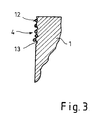
- Fig. 3 is a sectional view on a larger scale a contact surface 4 is shown on the finished section 1.
- a contact surface 4 is shown on the finished section 1.
- the sectional view when pouring of the molding space 7 in the area of the molding surface 9 made of the molding material of the shaped element 8 partially separated particles 12 and embedded in the metal material of section 1, so that corresponding projections are formed here. So far the Particles are not integrated into the metal material but if they fall out, there will be corresponding depressions 13 molded into the contact surface so that overall gives a highly structured surface, the Roughness not only due to the size of the integrated Particles 12 and / or those formed by coarse particles Wells 13 is defined, but also by the molded Wells 13 so that a surface structure with there is a clear surface roughness.
- the shaped element 8 expediently contains at least in its the roughening area forming an admixture of at least a metal oxide.
- a mixture is also expedient, which at least in the part of the molding material which forms the rough surface is provided with metal particles, expediently the metal particles one compared to the melting temperature of the first metal material have a lower melting temperature. This not only results in a positive integration the coarse particle 12 in the first metal material, but it also arises between the individual particles another kind of metallic matrix that improves the integration. Are the metal particles made of the second metal material or a metal or metal material that can be alloyed with this, then results when casting with the second metal material between this and the matrix of the rough surface a metallic connection.
- the method according to the invention thus offers the advantage that two metal materials that cannot be connected to one another by melting firmly together when creating a component can be connected.
- the first metal material is preferred an iron material is used, in particular a gray cast iron material.
- second metal material is a non-ferrous metal material, preferably a light metal material, especially an aluminum material intended.
- foundry molding sand is expedient as the molding material for the molding element. It is expedient here if the molding material additionally contains iron oxide (Fe 2 O 3 ) as the metal oxide.
- the admixture of iron oxide to the molding sand results in a rough surface which is formed by so-called mineralization between the first metal material, which consists, for example, of a gray cast iron material, and the molding material components incorporated by the gray cast iron.
- the method according to the invention is not only for the exemplary embodiment specified process for casting cast iron cylinder liners applicable in a light alloy engine block.
- the procedure can basically be used in all cases in which one or more sections, usually load-bearing Parts of the overall construction, from a resilient Casting material can be created, which is then in a second mold together with other cores or other shaping parts inserted and according to the shape for the finished cast workpiece with the second metal material be cast around, in particular with a double-walled Execution of the cast workpiece the two metal materials only in predetermined areas given by the contact areas are in contact with one another and in these areas cause a firm connection between the two metal materials.
- the shaped elements forming the rough surfaces of the first Casting mold also formed by parts of the casting mold itself become.
- the surface area of the casting mold that forms the rough surface for example with an easily evaporating binder provided or to moisten the existing pore volume, so that when casting, it’s normally in the manufacture of Cast workpieces undesirable incorporation of particles of the molding material the mold into the surface of the casting workpiece he follows.
Landscapes
- Engineering & Computer Science (AREA)
- Mechanical Engineering (AREA)
- Molds, Cores, And Manufacturing Methods Thereof (AREA)
- Cylinder Crankcases Of Internal Combustion Engines (AREA)
- Forging (AREA)
Applications Claiming Priority (2)
| Application Number | Priority Date | Filing Date | Title |
|---|---|---|---|
| DE2001103596 DE10103596A1 (de) | 2001-01-26 | 2001-01-26 | Verfahren zur Herstellung eines aus wenigstens zwei unterschiedlichen Metallwerkstoffen gebildeten Gußwerkstücks |
| DE10103596 | 2001-01-26 |
Publications (2)
| Publication Number | Publication Date |
|---|---|
| EP1226889A2 true EP1226889A2 (fr) | 2002-07-31 |
| EP1226889A3 EP1226889A3 (fr) | 2003-01-22 |
Family
ID=7671884
Family Applications (1)
| Application Number | Title | Priority Date | Filing Date |
|---|---|---|---|
| EP02000907A Withdrawn EP1226889A3 (fr) | 2001-01-26 | 2002-01-16 | Procédé de fabrication d'une pièce coulée constituée d'au moins deux matériaux métalliques différents |
Country Status (2)
| Country | Link |
|---|---|
| EP (1) | EP1226889A3 (fr) |
| DE (1) | DE10103596A1 (fr) |
Cited By (3)
| Publication number | Priority date | Publication date | Assignee | Title |
|---|---|---|---|---|
| WO2003000447A3 (fr) * | 2001-06-23 | 2003-03-13 | Mahle Gmbh | Procede de fabrication d'une douille de palier en alliage leger a surface rugueuse |
| EP1398492A1 (fr) * | 2002-09-11 | 2004-03-17 | Honda Giken Kogyo Kabushiki Kaisha | Procédé de fabrication d'un bloc-cylindres avec chemise |
| DE102005019961A1 (de) * | 2005-04-29 | 2006-11-02 | Audi Ag | Verfahren zur Herstellung eines Gussteiles im Verbundguss |
Families Citing this family (4)
| Publication number | Priority date | Publication date | Assignee | Title |
|---|---|---|---|---|
| DE10224130A1 (de) * | 2002-05-29 | 2003-12-18 | Vaw Mandl & Berger Gmbh Linz | Verfahren zum Herstellen eines Motorblocks aus einem Metallgusswerkstoff, Gießform zur Herstellung eines Motorblocks aus Metallgusswerkstoff und Motorblock aus Metallgusswerkstoff |
| DE10251426A1 (de) * | 2002-11-05 | 2004-05-13 | Volkswagen Ag | Verfahren zum Herstellen eines Zylinderkurbelgehäuses |
| DE502005010834D1 (de) | 2005-02-03 | 2011-02-24 | Ford Werke Gmbh | Verfahren zur Herstellung einer metallischen Haftvermittlungsschicht auf einem Umgusskörper |
| DE102024111331A1 (de) * | 2024-04-23 | 2025-10-23 | Mahle International Gmbh | Verfahren zur Herstellung eines Motorflansches für einen Elektromotor |
Family Cites Families (12)
| Publication number | Priority date | Publication date | Assignee | Title |
|---|---|---|---|---|
| CH366636A (fr) * | 1959-12-28 | 1963-01-15 | Nat Lead Co | Organe de machine et procédé pour sa fabrication |
| DE3205952A1 (de) * | 1981-09-12 | 1983-03-31 | J. Wizemann Gmbh U. Co, 7000 Stuttgart | Nockenwelle |
| DE19537847A1 (de) * | 1995-10-11 | 1997-04-17 | Mahle Gmbh | Bewehrungsteil, dessen Grundwerkstoff austenitisches Gußeisen ist |
| DE19634504A1 (de) * | 1996-08-27 | 1997-12-04 | Daimler Benz Ag | In ein Leichtmetall-Gußteil einzugießender Rohling eines anderen Leichtmetallteiles und Verfahren zum Herstellen eines solchen Rohlinges |
| DE19750687A1 (de) * | 1997-11-15 | 1999-05-20 | Ks Aluminium Technologie Ag | Verfahren zum Eingießen von Eingußteilen |
| DE19807688C2 (de) * | 1998-02-25 | 2003-06-26 | Daimler Chrysler Ag | Verwendung einer chromfreien Konversionslösung auf Zirkonbasis als Schutzfilm auf einzugießenden Leichtmetall-Rohlingen einer Zylinderlaufbüchse |
| DE19807685C2 (de) * | 1998-02-25 | 2000-11-09 | Daimler Chrysler Ag | Verfahren zum Herstellen von aus einer Leichtmetall-Legierung bestehenden Rohlingen einer Zylinderlaufbüchse |
| DE19857390C1 (de) * | 1998-12-12 | 2000-04-06 | Daimler Chrysler Ag | Verfahren zur Herstellung eines Kurbelgehäuses für eine Brennkraftmaschine |
| DE19859098C1 (de) * | 1998-12-21 | 2000-03-02 | Wolfgang Eberlein | Zylinderlaufbuchse aus Grauguß zum Eingießen in einen aus Leichtmetallguß bestehenden Motorblock eines Verbrennungsmotors |
| DE19958185A1 (de) * | 1999-12-02 | 2001-06-07 | Mahle Ventiltrieb Gmbh | Verlorene Form zur Herstellung einer Zylinderlaufbuchse |
| JP3253605B2 (ja) * | 1999-12-15 | 2002-02-04 | テーピ工業株式会社 | 鋳ぐるみ用鋳鉄部材、それを用いた鋳ぐるみ製品、及び鋳ぐるみ用鋳鉄部材の製造方法 |
| DE10009135A1 (de) * | 2000-02-26 | 2001-08-30 | Volkswagen Ag | Laufbuchsen aus einer Aluminiumlegierung zum Eingießen in Zylinderblöcke aus Leichtmetall von Verbrennungsmotoren und Verfahren zu deren Herstellung und Einguß |
-
2001
- 2001-01-26 DE DE2001103596 patent/DE10103596A1/de not_active Withdrawn
-
2002
- 2002-01-16 EP EP02000907A patent/EP1226889A3/fr not_active Withdrawn
Cited By (5)
| Publication number | Priority date | Publication date | Assignee | Title |
|---|---|---|---|---|
| WO2003000447A3 (fr) * | 2001-06-23 | 2003-03-13 | Mahle Gmbh | Procede de fabrication d'une douille de palier en alliage leger a surface rugueuse |
| US6957489B2 (en) | 2001-06-23 | 2005-10-25 | Mahle Gmbh | Method for producing a light-alloy bearing bush with a rough external surface |
| EP1398492A1 (fr) * | 2002-09-11 | 2004-03-17 | Honda Giken Kogyo Kabushiki Kaisha | Procédé de fabrication d'un bloc-cylindres avec chemise |
| US6925981B2 (en) | 2002-09-11 | 2005-08-09 | Honda Giken Kogyo Kabushiki Kaisha | Process for producing a cylinder block with a sleeve |
| DE102005019961A1 (de) * | 2005-04-29 | 2006-11-02 | Audi Ag | Verfahren zur Herstellung eines Gussteiles im Verbundguss |
Also Published As
| Publication number | Publication date |
|---|---|
| EP1226889A3 (fr) | 2003-01-22 |
| DE10103596A1 (de) | 2002-08-01 |
Similar Documents
| Publication | Publication Date | Title |
|---|---|---|
| DE69025288T2 (de) | Vollformgiessen eines Motorblockes aus zwei Legierungen | |
| DE102007023152A1 (de) | Verfahren zur Herstellung eines Gussteils, Gussform und damit hergestelltes Gussteil | |
| EP1398098A1 (fr) | Procédé pour la fabrication d'aubes de turbine avec des canaux de refroidissement | |
| EP2091678A1 (fr) | Moule de coulée pour la coulée d'une pièce et utilisation de ce moule de coulée | |
| DE10058428B4 (de) | Zylinderlaufbuchse und Zylinderblock sowie Verfahren zur Herstellung derselben | |
| DE2919477C2 (de) | Verschleißfester Verbundwerkstoff, Verfahren zu seiner Herstellung und Verwendung des Verbundwerkstoffes | |
| DE69223178T2 (de) | Verfahren zur herstellung von gegossenen zusammengesetzten zylinderköpfen | |
| DE60100457T2 (de) | Ein verfahren zur herstellung eines zylinderblocks für eine brennkraftmaschiene | |
| DE2630541A1 (de) | Verfahren zur herstellung eines aluminium-gussteiles mit verschleissfesten oberflaechenpartien | |
| EP1226889A2 (fr) | Procédé de fabrication d'une pièce coulée constituée d'au moins deux matériaux métalliques différents | |
| DE19826848C5 (de) | Leichtmetallrad für Kraftfahrzeuge | |
| DE19859098C1 (de) | Zylinderlaufbuchse aus Grauguß zum Eingießen in einen aus Leichtmetallguß bestehenden Motorblock eines Verbrennungsmotors | |
| EP1390168B1 (fr) | Moule et procede pour la production d'un modele de coulee en mousse perdu pour la coulee d'une chemise de cylindre en metal leger | |
| DE112010001446B4 (de) | Verfahren zur Herstellung einer Zylinderlaufbuchse aus Metallmatrix-Verbundwerkstoffund Verfahren zur Herstellung derselben | |
| DE102018221826B4 (de) | Verfahren zum Herstellen eines Kerns sowie nach dem Verfahren hergestellter Gießkern | |
| DE102013015431A1 (de) | Verfahren zum Herstellen eines gegossenen metallischen Bauteiles und gegossenes metallisches Bauteil | |
| DE10219779A1 (de) | Verfahren zur Herstellung eines Kolbens und nach dem Verfahren hergestellter Kolben | |
| DE3200641A1 (de) | Verfahren und vorrichtung zum giessen von, eine abriebbestaendige einlage aufweisenden leichtmetall-kolben | |
| DE19912692C2 (de) | Zylinderblock für einen Kolbenmotor | |
| DE102021110317A1 (de) | Hybridkern für die herstellung von gussteilen | |
| EP1216771A9 (fr) | Noyau inséré pour la fabrication d'un moule de fonderie et procédé pour la fabrication d'un tel moule de fonderie | |
| EP2089173A1 (fr) | Carter moteur pour un véhicule automobile | |
| DE102018109620A1 (de) | Sandkern zur eliminierung von oberflächenzerfall | |
| DE102007060502A1 (de) | Verfahren zur Herstellung eines Zylinderkurbelgehäuses | |
| DE4442453A1 (de) | Gießverfahren für ein Bauteil, insbesondere aus Leichtmetall |
Legal Events
| Date | Code | Title | Description |
|---|---|---|---|
| PUAI | Public reference made under article 153(3) epc to a published international application that has entered the european phase |
Free format text: ORIGINAL CODE: 0009012 |
|
| AK | Designated contracting states |
Kind code of ref document: A2 Designated state(s): AT BE CH CY DE DK ES FI FR GB GR IE IT LI LU MC NL PT SE TR |
|
| AX | Request for extension of the european patent |
Free format text: AL;LT;LV;MK;RO;SI |
|
| PUAL | Search report despatched |
Free format text: ORIGINAL CODE: 0009013 |
|
| AK | Designated contracting states |
Kind code of ref document: A3 Designated state(s): AT BE CH CY DE DK ES FI FR GB GR IE IT LI LU MC NL PT SE TR |
|
| AX | Request for extension of the european patent |
Free format text: AL;LT;LV;MK;RO;SI |
|
| AKX | Designation fees paid |
Designated state(s): AT BE CH CY DE DK ES FI FR GB GR IE IT LI LU MC NL PT SE TR |
|
| STAA | Information on the status of an ep patent application or granted ep patent |
Free format text: STATUS: THE APPLICATION IS DEEMED TO BE WITHDRAWN |
|
| 18D | Application deemed to be withdrawn |
Effective date: 20030723 |