EP1227208A2 - Abdeckung für flexible Signal-Verbindung für die Tür eines LKW's - Google Patents
Abdeckung für flexible Signal-Verbindung für die Tür eines LKW's Download PDFInfo
- Publication number
- EP1227208A2 EP1227208A2 EP01129218A EP01129218A EP1227208A2 EP 1227208 A2 EP1227208 A2 EP 1227208A2 EP 01129218 A EP01129218 A EP 01129218A EP 01129218 A EP01129218 A EP 01129218A EP 1227208 A2 EP1227208 A2 EP 1227208A2
- Authority
- EP
- European Patent Office
- Prior art keywords
- cover
- door
- passage
- outer cover
- signal connection
- Prior art date
- Legal status (The legal status is an assumption and is not a legal conclusion. Google has not performed a legal analysis and makes no representation as to the accuracy of the status listed.)
- Granted
Links
Images




Classifications
-
- H—ELECTRICITY
- H02—GENERATION; CONVERSION OR DISTRIBUTION OF ELECTRIC POWER
- H02G—INSTALLATION OF ELECTRIC CABLES OR LINES, OR OF COMBINED OPTICAL AND ELECTRIC CABLES OR LINES
- H02G11/00—Arrangements of electric cables or lines between relatively-movable parts
-
- E—FIXED CONSTRUCTIONS
- E05—LOCKS; KEYS; WINDOW OR DOOR FITTINGS; SAFES
- E05D—HINGES OR SUSPENSION DEVICES FOR DOORS, WINDOWS OR WINGS
- E05D11/00—Additional features or accessories of hinges
- E05D11/0054—Covers, e.g. for protection
-
- E—FIXED CONSTRUCTIONS
- E05—LOCKS; KEYS; WINDOW OR DOOR FITTINGS; SAFES
- E05F—DEVICES FOR MOVING WINGS INTO OPEN OR CLOSED POSITION; CHECKS FOR WINGS; WING FITTINGS NOT OTHERWISE PROVIDED FOR, CONCERNED WITH THE FUNCTIONING OF THE WING
- E05F15/00—Power-operated mechanisms for wings
- E05F15/40—Safety devices, e.g. detection of obstructions or end positions
- E05F15/42—Detection using safety edges
-
- E—FIXED CONSTRUCTIONS
- E05—LOCKS; KEYS; WINDOW OR DOOR FITTINGS; SAFES
- E05Y—INDEXING SCHEME ASSOCIATED WITH SUBCLASSES E05D AND E05F, RELATING TO CONSTRUCTION ELEMENTS, ELECTRIC CONTROL, POWER SUPPLY, POWER SIGNAL OR TRANSMISSION, USER INTERFACES, MOUNTING OR COUPLING, DETAILS, ACCESSORIES, AUXILIARY OPERATIONS NOT OTHERWISE PROVIDED FOR, APPLICATION THEREOF
- E05Y2900/00—Application of doors, windows, wings or fittings thereof
- E05Y2900/50—Application of doors, windows, wings or fittings thereof for vehicles
- E05Y2900/51—Application of doors, windows, wings or fittings thereof for vehicles for railway cars or mass transit vehicles
Definitions
- the present invention relates, in general, to transit vehicle door systems and, more particularly, the instant invention relates to covers for signal connections in transit vehicle door systems.
- Some transit vehicle door systems require signal connections between moveable door panels and stationary portions of the door systems. These signal connections may, for example, be electrical wires, or may be pneumatic tubes. Wires may be employed in electrical edge sensors for detecting an impact with a passenger or other obstruction, for safety lights, etc. Pneumatic tubes may be employed for convening an air pressure signal from a pneumatic door edge sensor to an air pressure sensor.
- Such signal connections may be provided with some protection by a flexible piece of tubing which is placed over the connections where the connections pass from the door panel to the stationary portion of the door system. Breakage of such signal connections is a common maintenance problem in such door systems. Breakage may be caused by an object carried by a passenger catching on the signal connections, by vandalism, or by fatigue due to repeated movement between open and closed positions of the door. Gravity, tending to bend slack signal connections downward, contributes to fatigue.
- the present invention is a cover system for at least one flexible signal connection in a door system for a transit vehicle, the door system including at least one door panel mounted to open and close by rotation about an axis.
- the cover system includes an outer cover for the flexible signal connection(s), the outer cover being for attachment to either a stationary portion of the transit vehicle door system or one of the door panels.
- the outer cover encloses a first passage.
- the cover system also has an inner cover for the flexible signal connection(s), the inner cover being for attachment to the opposite one of the stationary portion of the transit vehicle door system and the door panel.
- the inner cover is positionable within the first passage while the door panel rotates about the axis between an open position and a closed position of the door panel.
- the inner cover has a second passage therein, the second passage being for the flexible signal connection(s).
- the present invention is a door system for a transit vehicle. It includes a stationary portion for attachment to the transit vehicle, at least one door panel mounted on the stationary portion to be moved between an open position and a closed position by rotation about an axis, and at least one flexible signal connection passing from the stationary portion of the door system to the door panel. There is also a cover system for the flexible signal connection(s), the cover system including an outer cover for the flexible signal connection(s), the outer cover attached to the stationary portion of the door system. The outer cover encloses a first passage. The cover system also includes an inner cover for the flexible signal connection(s).
- the inner cover is attached to the door panel, and is positioned to slide within the first passage in the outer cover as the door panel is moved between an open position and a closed position of the door panel.
- the inner cover encloses a second passage, the second passage being for the flexible signal connection(s).
- Another object of the present invention is to provide a cover for electric wires connected between stationary portions of a transit vehicle door system and moveable door panels.
- Still another object of the present invention is to provide a cover for pneumatic tubes connected between stationary portions of a transit vehicle door system and moveable door panels.
- Yet another object of the present invention is to protect flexible signal connections in a transit vehicle door system from inadvertent damage due to being caught on objects carried by passengers.
- a further object of the present invention is to protect flexible signal connections in a transit vehicle door system from damage due to vandalism.
- Another object of the present invention is to hide unsightly flexible signal connections to a door panel in a transit vehicle door system.
- Figure 1 is a view from inside a transit vehicle showing a pair of biparting door panels having signal connection covers according to the present invention.
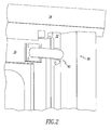
- Figure 2 is close-up of the cover for the signal connections on the right door panel.
- Figure 3 is an isometric view of an outer cover which is for attachment to stationary portions of the door system or vehicle, and is for signal connections on the right door panel.
- Figure 4 is an isometric view of an inner cover which slides inside the outer cover and which is for attachment to the right door panel.
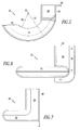
- Figure 5 is a top view of the outer cover for the right door panel.
- Figure 6 is a front view of the outer cover for the right door panel, viewed from inside the vehicle.
- Figure 7 is a side view of the outer cover for the right door panel viewed from the right.
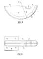
- Figure 8 is a top view of the inner cover oriented for the right door panel, taken from above the view shown in Figure 4.
- Figure 9 is a front view of the inner cover oriented for the right door panel.
- Figure 10 is a top view of the inner cover and outer cover assembled for the right door panel and a flexible signal connection, the right door panel being closed.
- Figure 11 is a view similar to that shown in Figure 10 except that the right door panel is in its open position.
- Figure 12 is a view of the cover system installed, and the flexible signal connections passing through a linear portion of the outer cover to an overhead door operator.
- Figure 13 is a view of an outer cover in which the arcuate portion has an angular extent of about 135 degrees.
- FIGs 1 and 2 illustrate a transit vehicle, generally designated 10, having a door system, generally designated 20.
- Door system 20 includes right door panel 24 and left door panel 24L.
- Door system 20 also includes a stationary portion, generally designated 30, having a door frame member 32 and overhead door operator 34.
- Flexible signal connection 22 shown in Figures 10, 11 and 12 passes from stationary portion 30 of door system 20 to door panel 24, and a similar flexible signal connection (not shown) passes from stationary portion 30 of door system 20 to door panel 24L.
- the invention provides a cover system, generally designated 40, for covering flexible signal connection 22 to the right door panel 24 and a cover system 40L for covering a similar signal connection to the left door panel 24L.
- Cover system 40L is mirror symmetric with cover system 40 and will therefore not be described in detail.
- Cover system 40 includes an outer cover, generally designated 50, which is illustrated in Figure 3 and an inner cover, generally designated 70, which is illustrated in Figure 4.
- outer cover 50 is attached to stationary portion 30 of transit vehicle door system 20.
- outer cover 50 is attached to frame member 32 of stationary portion 30 by flange 58.
- Outer cover 50 preferably, has a linear portion 56 and an arcuate portion 52.
- Outer cover 50 encloses a first passage, generally designated 60.
- Inner cover 70 is, preferably, attached to door panel 24 by flange 76, and it fits inside first passage 60 in outer cover 50. It is preferred that cover system 40 be entirely disposed within transit vehicle 10 when right door panel 24 is closed, as illustrated in Figures 1 and 2.
- inner cover 70 has a pair of semi circular surface members 73, connected by bridge portion 74.
- FIG. 5 shows the outer cover 50 from inside transit vehicle 10 and Figure 5 shows outer cover 50 from above.
- Linear portion 56 of outer cover 50 encloses linear portion 64 of first passage 60.
- Arcuate portion 52 encloses arcuate portion 62 of first passage 60.
- An inner radius 54 of arcuate portion 52, taken from center of curvature 53 and an outer radius 55 of arcuate portion 52 are illustrated in Figure 5.
- a view of outer cover 50, taken from the right, is shown in Figure 7.
- Figure 9 shows inner cover 70 without outer cover 50 from inside transit vehicle 10.
- Figure 8 shows inner cover 70 from above.
- Semi circular surface members 73 connected by bridge 74 are illustrated in these figures.
- a curved exterior 75 of inner cover 70 is shown.
- Curved exterior 75 has a radius of curvature 78 from center of curvature 71.
- Second passage 72 is enclosed by curved exterior 75, semi circular surface members 73 and bridge 74.
- Figures 10 and 11 illustrate the cover system 40 with the outer cover 50 attached to stationary portion 30 of door system 20.
- Figure 10 shows the cover system 40 when right door panel 24 is closed and
- Figure 12 shows the cover system 40 when right door panel 24 is open.
- Inner cover 70 is partially disposed within outer cover 50 and is attached to door panel 24.
- the flexible signal connection 22 is shown, enclosed by first passage 60 and second passage 72.
- Bridge 74 serves to secure flexible signal connection 22 within second passage 72.
- Figures 10 and 11 illustrate -radial movement of flexible signal connection 22 between the closed position of Figure 10 and the open position of Figure 11.
- flexible signal connection 22 is positioned near outer radius 55 of outer cover 50 and moves inward toward inner radius 54 of outer cover 50 as door panel 24 is opened.
- Figure 12 illustrates the flexible signal connection 22 passing through linear portion 64 of first passage 60 and through opening 36 into overhead door operator 34, which is included in the stationary portion 30 of door system 20.
- Figure 13 illustrates an alternative embodiment for an outer cover 150 in which arcuate portion 152 has an angular extent 151 of about 135 degrees.
Landscapes
- Power-Operated Mechanisms For Wings (AREA)
- Connector Housings Or Holding Contact Members (AREA)
- Rear-View Mirror Devices That Are Mounted On The Exterior Of The Vehicle (AREA)
Applications Claiming Priority (2)
| Application Number | Priority Date | Filing Date | Title |
|---|---|---|---|
| US09/772,230 US6572177B2 (en) | 2001-01-29 | 2001-01-29 | Cover for flexible signal connection for a transit vehicle door |
| US772230 | 2001-01-29 |
Publications (3)
| Publication Number | Publication Date |
|---|---|
| EP1227208A2 true EP1227208A2 (de) | 2002-07-31 |
| EP1227208A3 EP1227208A3 (de) | 2005-05-25 |
| EP1227208B1 EP1227208B1 (de) | 2007-02-07 |
Family
ID=25094377
Family Applications (1)
| Application Number | Title | Priority Date | Filing Date |
|---|---|---|---|
| EP01129218A Expired - Lifetime EP1227208B1 (de) | 2001-01-29 | 2001-12-10 | Abdeckung für flexible Signal-Verbindung für die Tür eines LKW's |
Country Status (7)
| Country | Link |
|---|---|
| US (1) | US6572177B2 (de) |
| EP (1) | EP1227208B1 (de) |
| CN (1) | CN1368441A (de) |
| AT (1) | ATE353292T1 (de) |
| CA (1) | CA2350375C (de) |
| DE (1) | DE60126471T2 (de) |
| MX (1) | MXPA01012524A (de) |
Cited By (1)
| Publication number | Priority date | Publication date | Assignee | Title |
|---|---|---|---|---|
| EP2963221A1 (de) * | 2014-07-03 | 2016-01-06 | MAN Truck & Bus AG | Schwenktürkonstruktion für ein fahrzeug, vorzugsweise einen omnibus |
Families Citing this family (9)
| Publication number | Priority date | Publication date | Assignee | Title |
|---|---|---|---|---|
| DE202005018419U1 (de) * | 2005-11-23 | 2007-03-29 | Dr. Hahn Gmbh & Co. Kg | Vorrichtung zur Führung von Leitungen zwischen einem Rahmen und einem Flügel |
| JP5063266B2 (ja) * | 2007-09-10 | 2012-10-31 | 矢崎総業株式会社 | 給電構造 |
| FR2929734A1 (fr) * | 2008-04-03 | 2009-10-09 | St Microelectronics Rousset | Procede et systeme de videosurveillance. |
| JP5860425B2 (ja) * | 2013-03-07 | 2016-02-16 | 川崎重工業株式会社 | 開き戸 |
| DE102013108973B3 (de) | 2013-08-20 | 2014-09-11 | Simonswerk, Gesellschaft mit beschränkter Haftung | Scharnier sowie Türanordnung |
| US9316032B2 (en) * | 2014-03-04 | 2016-04-19 | Honda Motor Co., Ltd. | Vehicle door checker |
| GB2570322B (en) * | 2018-01-19 | 2021-08-04 | Bentley Motors Ltd | A hinge cover and vehicle |
| GB2570321B (en) | 2018-01-19 | 2021-05-05 | Bentley Motors Ltd | A hinge cover and vehicle |
| CN109616983B (zh) * | 2018-12-05 | 2020-12-29 | 中国航空工业集团公司成都飞机设计研究所 | 一种管线与转轴的防干涉结构 |
Family Cites Families (6)
| Publication number | Priority date | Publication date | Assignee | Title |
|---|---|---|---|---|
| GB1347656A (en) * | 1972-02-11 | 1974-02-27 | Messerschmitt Boelkow Blohm | Guides for electrical cables |
| US3848361A (en) * | 1973-09-14 | 1974-11-19 | Von Duprin Inc | Conductor transfer assembly |
| FR2616390B1 (fr) * | 1987-06-12 | 1989-10-20 | Peugeot | Structure de montage d'un faisceau electrique de porte |
| US5039828A (en) * | 1989-09-21 | 1991-08-13 | Whirlpool Corporation | Wire harness protector and pivotable door assembly including same |
| US5332279A (en) * | 1993-05-17 | 1994-07-26 | Mark Iv Transportation Products Corp. | Power door operator for multi-passenger mass transit vehicles |
| US5466036A (en) * | 1994-05-09 | 1995-11-14 | Chrylser Corporation | Vehicle wire routing apparatus |
-
2001
- 2001-01-29 US US09/772,230 patent/US6572177B2/en not_active Expired - Lifetime
- 2001-06-13 CA CA002350375A patent/CA2350375C/en not_active Expired - Lifetime
- 2001-07-12 CN CN01122967A patent/CN1368441A/zh active Pending
- 2001-12-05 MX MXPA01012524A patent/MXPA01012524A/es active IP Right Grant
- 2001-12-10 DE DE60126471T patent/DE60126471T2/de not_active Expired - Lifetime
- 2001-12-10 AT AT01129218T patent/ATE353292T1/de not_active IP Right Cessation
- 2001-12-10 EP EP01129218A patent/EP1227208B1/de not_active Expired - Lifetime
Cited By (2)
| Publication number | Priority date | Publication date | Assignee | Title |
|---|---|---|---|---|
| EP2963221A1 (de) * | 2014-07-03 | 2016-01-06 | MAN Truck & Bus AG | Schwenktürkonstruktion für ein fahrzeug, vorzugsweise einen omnibus |
| RU2677389C2 (ru) * | 2014-07-03 | 2019-01-16 | Ман Трак Унд Бас Аг | Поворотная дверная конструкция для автомобиля, предпочтительно автобуса |
Also Published As
| Publication number | Publication date |
|---|---|
| MXPA01012524A (es) | 2002-08-06 |
| US6572177B2 (en) | 2003-06-03 |
| CA2350375A1 (en) | 2002-07-29 |
| CN1368441A (zh) | 2002-09-11 |
| DE60126471D1 (de) | 2007-03-22 |
| US20020101094A1 (en) | 2002-08-01 |
| CA2350375C (en) | 2004-11-23 |
| EP1227208A3 (de) | 2005-05-25 |
| ATE353292T1 (de) | 2007-02-15 |
| EP1227208B1 (de) | 2007-02-07 |
| DE60126471T2 (de) | 2007-11-08 |
Similar Documents
| Publication | Publication Date | Title |
|---|---|---|
| US6152519A (en) | Drive arrangement for sliding doors in motor vehicles | |
| CA2350375C (en) | Cover for flexible signal connection for a transit vehicle door | |
| US4119341A (en) | Rear window assembly for a truck cab | |
| US5379553A (en) | Door structure for vehicle and method for assembling such door structure | |
| US6918208B2 (en) | Lead screw window regulator | |
| US5816307A (en) | Aircraft window assembly having a circular, rotatable lens | |
| WO1995003470A1 (en) | Screen for use with a vehicle window | |
| US7111893B2 (en) | Hinged door module bracket | |
| PT1039259E (pt) | Escotilha para carros blindados | |
| JP2001105868A (ja) | リアハッチゲートハーネス配索こう造 | |
| CN101384850B (zh) | 飞机驾驶舱的可开启窗户的电缆的保护和导引装置 | |
| JP2003175767A (ja) | 赤外線カメラ及び赤外線カメラ搭載車両 | |
| JPH0925765A (ja) | ウインドレギュレータ | |
| CN116409253A (zh) | 车辆组件及其感测模块和连动式感测套组 | |
| US20030056320A1 (en) | Side load balance cord terminal clip | |
| JP2000247192A (ja) | 自動車のバックドアにおけるガラスハッチへのワイヤハーネス配索構造 | |
| CN110958799B (zh) | 高速公路门架系统控制器的翻盖外壳 | |
| CN218703118U (zh) | 驾驶区玻璃安装结构 | |
| JP2002258393A (ja) | カメラハウジング | |
| EP4691853A1 (de) | System zur befestigung einer indirekten sichtvorrichtung an einem fahrzeug | |
| JP2542894Y2 (ja) | 自動扉の戸先スイッチ | |
| JPH0663778U (ja) | ドア開閉部の安全装置 | |
| JPH11228060A (ja) | エレベータ出入口の安全装置 | |
| KR200153378Y1 (ko) | 차량용 도어의 체커 일체형 힌지구조 | |
| JPH0512088Y2 (de) |
Legal Events
| Date | Code | Title | Description |
|---|---|---|---|
| PUAI | Public reference made under article 153(3) epc to a published international application that has entered the european phase |
Free format text: ORIGINAL CODE: 0009012 |
|
| AK | Designated contracting states |
Kind code of ref document: A2 Designated state(s): AT BE CH CY DE DK ES FI FR GB GR IE IT LI LU MC NL PT SE TR |
|
| AX | Request for extension of the european patent |
Free format text: AL;LT;LV;MK;RO;SI |
|
| PUAL | Search report despatched |
Free format text: ORIGINAL CODE: 0009013 |
|
| AK | Designated contracting states |
Kind code of ref document: A3 Designated state(s): AT BE CH CY DE DK ES FI FR GB GR IE IT LI LU MC NL PT SE TR |
|
| AX | Request for extension of the european patent |
Extension state: AL LT LV MK RO SI |
|
| RIC1 | Information provided on ipc code assigned before grant |
Ipc: 7B 60R 16/02 A Ipc: 7H 02G 11/00 B |
|
| 17P | Request for examination filed |
Effective date: 20051021 |
|
| AKX | Designation fees paid |
Designated state(s): AT BE CH CY DE DK ES FI FR GB GR IE IT LI LU MC NL PT SE TR |
|
| GRAP | Despatch of communication of intention to grant a patent |
Free format text: ORIGINAL CODE: EPIDOSNIGR1 |
|
| GRAS | Grant fee paid |
Free format text: ORIGINAL CODE: EPIDOSNIGR3 |
|
| GRAA | (expected) grant |
Free format text: ORIGINAL CODE: 0009210 |
|
| AK | Designated contracting states |
Kind code of ref document: B1 Designated state(s): AT BE CH CY DE DK ES FI FR GB GR IE IT LI LU MC NL PT SE TR |
|
| PG25 | Lapsed in a contracting state [announced via postgrant information from national office to epo] |
Ref country code: BE Free format text: LAPSE BECAUSE OF FAILURE TO SUBMIT A TRANSLATION OF THE DESCRIPTION OR TO PAY THE FEE WITHIN THE PRESCRIBED TIME-LIMIT Effective date: 20070207 Ref country code: DK Free format text: LAPSE BECAUSE OF FAILURE TO SUBMIT A TRANSLATION OF THE DESCRIPTION OR TO PAY THE FEE WITHIN THE PRESCRIBED TIME-LIMIT Effective date: 20070207 Ref country code: CH Free format text: LAPSE BECAUSE OF FAILURE TO SUBMIT A TRANSLATION OF THE DESCRIPTION OR TO PAY THE FEE WITHIN THE PRESCRIBED TIME-LIMIT Effective date: 20070207 Ref country code: LI Free format text: LAPSE BECAUSE OF FAILURE TO SUBMIT A TRANSLATION OF THE DESCRIPTION OR TO PAY THE FEE WITHIN THE PRESCRIBED TIME-LIMIT Effective date: 20070207 Ref country code: FI Free format text: LAPSE BECAUSE OF FAILURE TO SUBMIT A TRANSLATION OF THE DESCRIPTION OR TO PAY THE FEE WITHIN THE PRESCRIBED TIME-LIMIT Effective date: 20070207 Ref country code: NL Free format text: LAPSE BECAUSE OF FAILURE TO SUBMIT A TRANSLATION OF THE DESCRIPTION OR TO PAY THE FEE WITHIN THE PRESCRIBED TIME-LIMIT Effective date: 20070207 Ref country code: AT Free format text: LAPSE BECAUSE OF FAILURE TO SUBMIT A TRANSLATION OF THE DESCRIPTION OR TO PAY THE FEE WITHIN THE PRESCRIBED TIME-LIMIT Effective date: 20070207 |
|
| REG | Reference to a national code |
Ref country code: GB Ref legal event code: FG4D |
|
| REG | Reference to a national code |
Ref country code: CH Ref legal event code: EP |
|
| REG | Reference to a national code |
Ref country code: IE Ref legal event code: FG4D |
|
| REF | Corresponds to: |
Ref document number: 60126471 Country of ref document: DE Date of ref document: 20070322 Kind code of ref document: P |
|
| PG25 | Lapsed in a contracting state [announced via postgrant information from national office to epo] |
Ref country code: SE Free format text: LAPSE BECAUSE OF FAILURE TO SUBMIT A TRANSLATION OF THE DESCRIPTION OR TO PAY THE FEE WITHIN THE PRESCRIBED TIME-LIMIT Effective date: 20070507 |
|
| PG25 | Lapsed in a contracting state [announced via postgrant information from national office to epo] |
Ref country code: ES Free format text: LAPSE BECAUSE OF FAILURE TO SUBMIT A TRANSLATION OF THE DESCRIPTION OR TO PAY THE FEE WITHIN THE PRESCRIBED TIME-LIMIT Effective date: 20070518 |
|
| PG25 | Lapsed in a contracting state [announced via postgrant information from national office to epo] |
Ref country code: PT Free format text: LAPSE BECAUSE OF FAILURE TO SUBMIT A TRANSLATION OF THE DESCRIPTION OR TO PAY THE FEE WITHIN THE PRESCRIBED TIME-LIMIT Effective date: 20070709 |
|
| NLV1 | Nl: lapsed or annulled due to failure to fulfill the requirements of art. 29p and 29m of the patents act | ||
| REG | Reference to a national code |
Ref country code: CH Ref legal event code: PL |
|
| ET | Fr: translation filed | ||
| PLBE | No opposition filed within time limit |
Free format text: ORIGINAL CODE: 0009261 |
|
| STAA | Information on the status of an ep patent application or granted ep patent |
Free format text: STATUS: NO OPPOSITION FILED WITHIN TIME LIMIT |
|
| 26N | No opposition filed |
Effective date: 20071108 |
|
| PG25 | Lapsed in a contracting state [announced via postgrant information from national office to epo] |
Ref country code: GR Free format text: LAPSE BECAUSE OF FAILURE TO SUBMIT A TRANSLATION OF THE DESCRIPTION OR TO PAY THE FEE WITHIN THE PRESCRIBED TIME-LIMIT Effective date: 20070508 |
|
| PG25 | Lapsed in a contracting state [announced via postgrant information from national office to epo] |
Ref country code: MC Free format text: LAPSE BECAUSE OF NON-PAYMENT OF DUE FEES Effective date: 20071231 |
|
| PG25 | Lapsed in a contracting state [announced via postgrant information from national office to epo] |
Ref country code: IE Free format text: LAPSE BECAUSE OF NON-PAYMENT OF DUE FEES Effective date: 20071210 |
|
| PG25 | Lapsed in a contracting state [announced via postgrant information from national office to epo] |
Ref country code: CY Free format text: LAPSE BECAUSE OF FAILURE TO SUBMIT A TRANSLATION OF THE DESCRIPTION OR TO PAY THE FEE WITHIN THE PRESCRIBED TIME-LIMIT Effective date: 20070207 |
|
| PG25 | Lapsed in a contracting state [announced via postgrant information from national office to epo] |
Ref country code: LU Free format text: LAPSE BECAUSE OF NON-PAYMENT OF DUE FEES Effective date: 20071210 |
|
| PG25 | Lapsed in a contracting state [announced via postgrant information from national office to epo] |
Ref country code: TR Free format text: LAPSE BECAUSE OF FAILURE TO SUBMIT A TRANSLATION OF THE DESCRIPTION OR TO PAY THE FEE WITHIN THE PRESCRIBED TIME-LIMIT Effective date: 20070207 |
|
| PGFP | Annual fee paid to national office [announced via postgrant information from national office to epo] |
Ref country code: FR Payment date: 20101224 Year of fee payment: 10 |
|
| PGFP | Annual fee paid to national office [announced via postgrant information from national office to epo] |
Ref country code: GB Payment date: 20101208 Year of fee payment: 10 Ref country code: IT Payment date: 20101218 Year of fee payment: 10 |
|
| PGFP | Annual fee paid to national office [announced via postgrant information from national office to epo] |
Ref country code: DE Payment date: 20101208 Year of fee payment: 10 |
|
| GBPC | Gb: european patent ceased through non-payment of renewal fee |
Effective date: 20111210 |
|
| REG | Reference to a national code |
Ref country code: FR Ref legal event code: ST Effective date: 20120831 |
|
| REG | Reference to a national code |
Ref country code: DE Ref legal event code: R119 Ref document number: 60126471 Country of ref document: DE Effective date: 20120703 |
|
| PG25 | Lapsed in a contracting state [announced via postgrant information from national office to epo] |
Ref country code: GB Free format text: LAPSE BECAUSE OF NON-PAYMENT OF DUE FEES Effective date: 20111210 Ref country code: DE Free format text: LAPSE BECAUSE OF NON-PAYMENT OF DUE FEES Effective date: 20120703 |
|
| PG25 | Lapsed in a contracting state [announced via postgrant information from national office to epo] |
Ref country code: IT Free format text: LAPSE BECAUSE OF NON-PAYMENT OF DUE FEES Effective date: 20111210 |
|
| PG25 | Lapsed in a contracting state [announced via postgrant information from national office to epo] |
Ref country code: FR Free format text: LAPSE BECAUSE OF NON-PAYMENT OF DUE FEES Effective date: 20120102 |