EP1227551A2 - Stecker mit Zugentlastungsklemme - Google Patents
Stecker mit Zugentlastungsklemme Download PDFInfo
- Publication number
- EP1227551A2 EP1227551A2 EP02001058A EP02001058A EP1227551A2 EP 1227551 A2 EP1227551 A2 EP 1227551A2 EP 02001058 A EP02001058 A EP 02001058A EP 02001058 A EP02001058 A EP 02001058A EP 1227551 A2 EP1227551 A2 EP 1227551A2
- Authority
- EP
- European Patent Office
- Prior art keywords
- housing part
- cable
- flat conductor
- bar
- plug connector
- Prior art date
- Legal status (The legal status is an assumption and is not a legal conclusion. Google has not performed a legal analysis and makes no representation as to the accuracy of the status listed.)
- Granted
Links
Images



Classifications
-
- H—ELECTRICITY
- H01—ELECTRIC ELEMENTS
- H01R—ELECTRICALLY-CONDUCTIVE CONNECTIONS; STRUCTURAL ASSOCIATIONS OF A PLURALITY OF MUTUALLY-INSULATED ELECTRICAL CONNECTING ELEMENTS; COUPLING DEVICES; CURRENT COLLECTORS
- H01R13/00—Details of coupling devices of the kinds covered by groups H01R12/70 or H01R24/00 - H01R33/00
- H01R13/58—Means for relieving strain on wire connection, e.g. cord grip, for avoiding loosening of connections between wires and terminals within a coupling device terminating a cable
- H01R13/582—Means for relieving strain on wire connection, e.g. cord grip, for avoiding loosening of connections between wires and terminals within a coupling device terminating a cable the cable being clamped between assembled parts of the housing
- H01R13/5829—Means for relieving strain on wire connection, e.g. cord grip, for avoiding loosening of connections between wires and terminals within a coupling device terminating a cable the cable being clamped between assembled parts of the housing the clamping part being flexibly or hingedly connected to the housing
-
- H—ELECTRICITY
- H01—ELECTRIC ELEMENTS
- H01R—ELECTRICALLY-CONDUCTIVE CONNECTIONS; STRUCTURAL ASSOCIATIONS OF A PLURALITY OF MUTUALLY-INSULATED ELECTRICAL CONNECTING ELEMENTS; COUPLING DEVICES; CURRENT COLLECTORS
- H01R12/00—Structural associations of a plurality of mutually-insulated electrical connecting elements, specially adapted for printed circuits, e.g. printed circuit boards [PCB], flat or ribbon cables, or like generally planar structures, e.g. terminal strips, terminal blocks; Coupling devices specially adapted for printed circuits, flat or ribbon cables, or like generally planar structures; Terminals specially adapted for contact with, or insertion into, printed circuits, flat or ribbon cables, or like generally planar structures
- H01R12/50—Fixed connections
- H01R12/59—Fixed connections for flexible printed circuits, flat or ribbon cables or like structures
- H01R12/65—Fixed connections for flexible printed circuits, flat or ribbon cables or like structures characterised by the terminal
- H01R12/67—Fixed connections for flexible printed circuits, flat or ribbon cables or like structures characterised by the terminal insulation penetrating terminals
- H01R12/68—Fixed connections for flexible printed circuits, flat or ribbon cables or like structures characterised by the terminal insulation penetrating terminals comprising deformable portions
Definitions
- the present invention relates to a plug connector with a strain relief clamp according to the main Claim 1.
- plug connectors are used, inter al, in airbag ignition systems, where compact construction and in particular, flat construction plug connectors, are important, since there is only a little height available for the incorporation of such a system into the steering wheel.
- a 100 % certainty that the electrical connection shall not be interrupted is an essential condition. If, during assembly, the electrical connection between the cable and the contact ends with possibly an electronic component such as a choke arranged between them, is interrupted in the plug connector through a tensile load, the airbag may not be released in an emergency.
- the purpose of the present invention is that of providing a plug connector of the kind set out at the beginning of the present specification, with a strain relief clamp, which safely prevents any interruption of the wiring within the plug connector.
- Fig. 1 shows the components of the plug connector 1 according to the invention.
- a first housing part 2 receives contact ends 3 in a plug 4, which is inserted into a corresponding counterplug.
- the contact ends 3 On the side of the cable, the contact ends 3 have contact frames, each of which, in the example shown, leads into a choke 7.
- This is connected to a crimp plate 5, the end of which on the side of the cable has sharp-edged tips, by means of which the insulation of the flat conductor strip is pierced and contact with the flat conductor strip is established.
- a second housing part 8 is inserted on the first housing part 2 via locking arms.
- the secondary locking device 22 is inserted through the second housing part as the plug 4.
- the second housing part has a strap 12 for holding a second bar 13, which is vertical to the length of the flat conductor strip 6.
- the first housing part 2 has at its end on the side of the cable, two limbs 18,19, between which is arranged a first bar 11.
- a third housing part 9 is, following the mutual insertion of the first and the second housing parts 2 and 8, inserted over the limbs 18,19, until it becomes locked into its final position.
- Fig. 2 shows an enlargement of the first and the second housing part.
- the second bar 13 of the second housing part 8 reaches, during the mutual insertion of the two housing parts and looking in the cable direction, behind the first bar of the first housing part and deforms stepwise the assembled flat conductor cable 6. During this process, the flat conductor cable 6 becomes clamped between the opposite side walls of the first and the second bar.
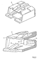
- Fig. 3 shows two perspective views of the third housing part, which is inserted on the limbs 18, 19. It can be seen from the partially cut open representation that the wall of the third housing part 9 on the side of the cable, has a slot 23, which the front ends of the limb 18 or 19 push through during the mutual insertion of the housing parts. In the inserted condition, the projecting limb ends can be pinched off on the approximate level of the slot 23. For this purpose, a break-off point 20 is provided, which makes possible the defined breaking off of the limb ends.
- On the lateral walls of the third housing part 9 can also be seen internal locking ramps 24, which the limbs 18,19 with corresponding complementary recesses, lock into.
- the upper face of the third housing part has provided at its inner edge on the side of the connector, a ramp-shaped chamfer 17, which comes into contact with the upper edge of the second bar 13 during the process of the mutual insertion of the housing parts and which forces the strap 12 downwards.
- the lower edge of the second bar 13 is pressed against the surface of the flat conductor cable 6, so that the flat conductor cable becomes deformed.
- a third bar 14 is provided at the end of the third housing part on the side of the cable.
- the third bar immediately adjoins the second bar and lies in the same plane with the latter, as well as with the first bar.
- the flat conductor cable 6 is - stepwise again bent upwards and clamped between the opposite lateral surfaces of the second and third bars 11 and 14.
- the flat conductor cable 6 emerges from the plug connector on the same level as that at which the end of the flat conductor cable is fixed to the crimp plate 5.
- the strain relief clamp 10 thus brings about a U-shaped deformation of the flat conductor cable and clamps it between the three bars. Any tearing out of the flat conductor cable is reliably prevented by means of the said clamping and by increased friction-generated retention.
- Fig. 4 shows the process of clamping, using the strain relief clamp according to the invention, during the mutual insertion of the third housing part 9 and the already mutually inserted first and second housing parts 2, 8. It can be seen from the top representation that the front edge of the strap 12 is bent slightly upwards. The front end of the flat conductor strip 6 is crimped to the crimp plate 5. By pressing down the strap 12, a first stage is stamped into the flat conductor cable 6 between the bars 11 and 13. During this process, the lower edge of the bar 13 presses the flat conductor cable 6 to the floor of the third housing part, which has already been inserted on the limbs 18,19. At this stage, the third housing part can be pushed over the strap 12.
- the ramp-shaped front edge 17 of the upper face of the third housing part 9 presses the strap 12 down further and the second bar 13 on the flat conductor cable 6, which now becomes clamped between the first and the second bars 11,13 and the floor of the housing part 9.
- the third housing part is inserted until its front edge- pushes against the corresponding faces of the first and second housing parts 2 and 8.
- the third housing part 9 is locked with the limbs 18,19 by the locking ramps 24 shown in Fig. 3.
- the third bar 14 which is arranged at the end on the side of the cable of the third housing part 9, approaches the second stay 13 so closely that the flat conductor cable 6 passing between the opposite lateral walls of the second and third bar, is clamped between them.
- the lateral wall of the second bar 13 on the side of the cable sustains an acute angle with the lower face, and the opposite lateral wall of the third bar 14 presses the flat conductor cable 6 until, as can be seen in the bottom illustration in Fig. 4, it has become S-shaped.
Landscapes
- Coupling Device And Connection With Printed Circuit (AREA)
- Multi-Conductor Connections (AREA)
- Details Of Connecting Devices For Male And Female Coupling (AREA)
Applications Claiming Priority (2)
| Application Number | Priority Date | Filing Date | Title |
|---|---|---|---|
| DE10102688 | 2001-01-22 | ||
| DE10102688A DE10102688C1 (de) | 2001-01-22 | 2001-01-22 | Steckverbinder mit Zugentlastung |
Publications (3)
| Publication Number | Publication Date |
|---|---|
| EP1227551A2 true EP1227551A2 (de) | 2002-07-31 |
| EP1227551A3 EP1227551A3 (de) | 2005-06-22 |
| EP1227551B1 EP1227551B1 (de) | 2006-08-16 |
Family
ID=7671316
Family Applications (1)
| Application Number | Title | Priority Date | Filing Date |
|---|---|---|---|
| EP02001058A Expired - Lifetime EP1227551B1 (de) | 2001-01-22 | 2002-01-21 | Stecker mit Zugentlastungsklemme |
Country Status (6)
| Country | Link |
|---|---|
| US (1) | US6634903B2 (de) |
| EP (1) | EP1227551B1 (de) |
| JP (1) | JP4142298B2 (de) |
| AT (1) | ATE336811T1 (de) |
| DE (2) | DE10102688C1 (de) |
| ES (1) | ES2269526T3 (de) |
Cited By (1)
| Publication number | Priority date | Publication date | Assignee | Title |
|---|---|---|---|---|
| EP1770829A1 (de) * | 2005-09-30 | 2007-04-04 | Yazaki Corporation | Verbinder |
Families Citing this family (11)
| Publication number | Priority date | Publication date | Assignee | Title |
|---|---|---|---|---|
| JP3614837B2 (ja) * | 2002-08-30 | 2005-01-26 | Smk株式会社 | 電線接続用プラグ |
| DE102004020933B3 (de) * | 2004-04-28 | 2005-12-29 | Tyco Electronics Amp Gmbh | Stecker, insbesondere Zündpillenstecker |
| TWM275558U (en) * | 2004-12-17 | 2005-09-11 | Hon Hai Prec Ind Co Ltd | Electrical card connector |
| DE102009001079B4 (de) * | 2009-02-23 | 2022-02-03 | Te Connectivity Germany Gmbh | Steckverbinderkörper, elektrischer Steckverbinder sowie Verfahren zum Montieren eines elektrischen Kabels in einem Steckverbinder |
| US8308505B2 (en) * | 2009-12-09 | 2012-11-13 | Scott Hatton | Guarded coaxial cable assembly |
| CN104124573B (zh) * | 2013-04-25 | 2017-11-10 | 日本光电工业株式会社 | 连接器 |
| WO2015102976A1 (en) * | 2013-12-31 | 2015-07-09 | 3M Innovative Properties Company | Right angle exit connector assembly |
| EP3116075B1 (de) * | 2015-07-08 | 2019-09-11 | Aptiv Technologies Limited | Elektrischer steckverbinder für ein sicherheitsrückhaltesystem |
| EP3734772B1 (de) * | 2019-04-30 | 2022-08-10 | Aptiv Technologies Limited | Elektrische kontaktklemme für einen elektrischen steckverbinder für ein sicherheitsrückhaltesystem |
| JP6966509B2 (ja) * | 2019-06-04 | 2021-11-17 | 矢崎総業株式会社 | コネクタ |
| US10727621B1 (en) * | 2019-07-10 | 2020-07-28 | LED Inspirations, LLC | Electrical connector system for LED tape lighting |
Family Cites Families (15)
| Publication number | Priority date | Publication date | Assignee | Title |
|---|---|---|---|---|
| US3336565A (en) * | 1964-03-26 | 1967-08-15 | Thomas & Betts Corp | Means for terminating flexible conductor etchings |
| US3813634A (en) * | 1972-12-29 | 1974-05-28 | Burndy Corp | Strain relief for flat cable or the like |
| GB2069254B (en) * | 1980-02-09 | 1985-04-17 | Crabtree Electrical Ind Ltd | Electric plug |
| US4734055A (en) * | 1981-12-30 | 1988-03-29 | Kitagawa Industries Co., Ltd. | Cord bushing |
| US5217389A (en) * | 1992-09-02 | 1993-06-08 | General Electric Company | Adjustable strain relief for wiring devices |
| US5266048A (en) * | 1993-03-26 | 1993-11-30 | The Whitaker Corporation | Gull-wing strain relief |
| US5575681A (en) * | 1994-12-16 | 1996-11-19 | Itt Corporation | Connector termination to flat cable |
| JPH08190971A (ja) * | 1995-01-10 | 1996-07-23 | Sumitomo Wiring Syst Ltd | ジョイントコネクタ |
| US5626491A (en) * | 1995-08-18 | 1997-05-06 | The Whitaker Corporation | Electrical connector strain relief for cable |
| US5599202A (en) * | 1996-01-22 | 1997-02-04 | Electrical Wiring Device Company, Inc. | Strain relief electrical connector |
| JP2000150030A (ja) * | 1998-11-17 | 2000-05-30 | Japan Aviation Electronics Industry Ltd | ケーブルコネクタ及びその結線方法 |
| JP2000323226A (ja) * | 1999-03-09 | 2000-11-24 | Sumitomo Wiring Syst Ltd | コネクタ |
| JP3265424B2 (ja) * | 1999-03-29 | 2002-03-11 | 日本航空電子工業株式会社 | ケーブルコネクタ及びその結線方法 |
| JP2001210409A (ja) * | 2000-01-28 | 2001-08-03 | Yazaki Corp | フラット回路体用のコネクタ及びフラット回路体のコネクタへの接続構造 |
| DE10025296C2 (de) * | 2000-05-22 | 2003-03-20 | Fci Automotive Deutschland Gmb | Steckverbinder, insbesondere für Airbag-Zündsysteme |
-
2001
- 2001-01-22 DE DE10102688A patent/DE10102688C1/de not_active Expired - Fee Related
-
2002
- 2002-01-21 ES ES02001058T patent/ES2269526T3/es not_active Expired - Lifetime
- 2002-01-21 EP EP02001058A patent/EP1227551B1/de not_active Expired - Lifetime
- 2002-01-21 DE DE60213891T patent/DE60213891T2/de not_active Expired - Lifetime
- 2002-01-21 AT AT02001058T patent/ATE336811T1/de not_active IP Right Cessation
- 2002-01-22 US US10/054,570 patent/US6634903B2/en not_active Expired - Fee Related
- 2002-01-22 JP JP2002013541A patent/JP4142298B2/ja not_active Expired - Fee Related
Cited By (2)
| Publication number | Priority date | Publication date | Assignee | Title |
|---|---|---|---|---|
| EP1770829A1 (de) * | 2005-09-30 | 2007-04-04 | Yazaki Corporation | Verbinder |
| US7381072B2 (en) | 2005-09-30 | 2008-06-03 | Yazaki Corporation | Connector having a strain relief structure |
Also Published As
| Publication number | Publication date |
|---|---|
| ES2269526T3 (es) | 2007-04-01 |
| DE60213891D1 (de) | 2006-09-28 |
| US6634903B2 (en) | 2003-10-21 |
| JP4142298B2 (ja) | 2008-09-03 |
| US20020115336A1 (en) | 2002-08-22 |
| DE60213891T2 (de) | 2007-09-13 |
| ATE336811T1 (de) | 2006-09-15 |
| EP1227551B1 (de) | 2006-08-16 |
| DE10102688C1 (de) | 2002-09-12 |
| EP1227551A3 (de) | 2005-06-22 |
| JP2002270285A (ja) | 2002-09-20 |
Similar Documents
| Publication | Publication Date | Title |
|---|---|---|
| US7144256B2 (en) | Connector arrangement between a flexible ribbon cable and a component | |
| US5380220A (en) | Connector | |
| EP1227551B1 (de) | Stecker mit Zugentlastungsklemme | |
| EP1035616B1 (de) | Crimpanschlussklemme für flexible Leiterplatte und Crimpanordnung für Leitungsader | |
| CN107548528B (zh) | 接线夹 | |
| KR100592360B1 (ko) | 기판 내장형 압접 커넥터 | |
| US6551129B2 (en) | Ground connector | |
| EP4173089B1 (de) | Verbinder für ein flexibles flachkabel | |
| US20060021783A1 (en) | Ground bus bar connector | |
| US6604966B1 (en) | Flexible cable electrical connector | |
| US4445742A (en) | Electrical cable connector | |
| US5921808A (en) | Ribbon cable plug-in connector | |
| JP7111884B2 (ja) | ダイレクト・プラグイン・コネクタ | |
| JP2001502464A (ja) | 封止された電気コネクタ | |
| EP0068656A1 (de) | Elektrischer Anschlusskontakt mit Hohlraumausgleichmittel | |
| US7591691B2 (en) | Plug-in connector | |
| JP3340325B2 (ja) | 複数段にケーブル列を配する電気コネクタ | |
| EP0600402B1 (de) | Elektrischer Verbinder mit verbesserter Kontakthalterung | |
| CN1199322C (zh) | 电连接器端子装置 | |
| US6340321B2 (en) | Electrical connector | |
| CN113889776B (zh) | 用于扁平柔性电缆的电气端子 | |
| JP2601193Y2 (ja) | 差込形接続端子 | |
| JP3544730B2 (ja) | 接続端子 | |
| US6565378B1 (en) | Electrical connector terminal and housing | |
| JP2002208451A (ja) | 圧接端子 |
Legal Events
| Date | Code | Title | Description |
|---|---|---|---|
| PUAI | Public reference made under article 153(3) epc to a published international application that has entered the european phase |
Free format text: ORIGINAL CODE: 0009012 |
|
| AK | Designated contracting states |
Kind code of ref document: A2 Designated state(s): AT BE CH CY DE DK ES FI FR GB GR IE IT LI LU MC NL PT SE TR |
|
| AX | Request for extension of the european patent |
Free format text: AL;LT;LV;MK;RO;SI |
|
| PUAL | Search report despatched |
Free format text: ORIGINAL CODE: 0009013 |
|
| AK | Designated contracting states |
Kind code of ref document: A3 Designated state(s): AT BE CH CY DE DK ES FI FR GB GR IE IT LI LU MC NL PT SE TR |
|
| AX | Request for extension of the european patent |
Extension state: AL LT LV MK RO SI |
|
| GRAP | Despatch of communication of intention to grant a patent |
Free format text: ORIGINAL CODE: EPIDOSNIGR1 |
|
| 17P | Request for examination filed |
Effective date: 20051222 |
|
| AKX | Designation fees paid |
Designated state(s): AT BE CH CY DE DK ES FI FR GB GR IE IT LI LU MC NL PT SE TR |
|
| GRAS | Grant fee paid |
Free format text: ORIGINAL CODE: EPIDOSNIGR3 |
|
| GRAA | (expected) grant |
Free format text: ORIGINAL CODE: 0009210 |
|
| RAP1 | Party data changed (applicant data changed or rights of an application transferred) |
Owner name: FCI |
|
| AK | Designated contracting states |
Kind code of ref document: B1 Designated state(s): AT BE CH CY DE DK ES FI FR GB GR IE IT LI LU MC NL PT SE TR |
|
| PG25 | Lapsed in a contracting state [announced via postgrant information from national office to epo] |
Ref country code: IT Free format text: LAPSE BECAUSE OF FAILURE TO SUBMIT A TRANSLATION OF THE DESCRIPTION OR TO PAY THE FEE WITHIN THE PRESCRIBED TIME-LIMIT;WARNING: LAPSES OF ITALIAN PATENTS WITH EFFECTIVE DATE BEFORE 2007 MAY HAVE OCCURRED AT ANY TIME BEFORE 2007. THE CORRECT EFFECTIVE DATE MAY BE DIFFERENT FROM THE ONE RECORDED. Effective date: 20060816 Ref country code: AT Free format text: LAPSE BECAUSE OF FAILURE TO SUBMIT A TRANSLATION OF THE DESCRIPTION OR TO PAY THE FEE WITHIN THE PRESCRIBED TIME-LIMIT Effective date: 20060816 Ref country code: FI Free format text: LAPSE BECAUSE OF FAILURE TO SUBMIT A TRANSLATION OF THE DESCRIPTION OR TO PAY THE FEE WITHIN THE PRESCRIBED TIME-LIMIT Effective date: 20060816 Ref country code: LI Free format text: LAPSE BECAUSE OF FAILURE TO SUBMIT A TRANSLATION OF THE DESCRIPTION OR TO PAY THE FEE WITHIN THE PRESCRIBED TIME-LIMIT Effective date: 20060816 Ref country code: CH Free format text: LAPSE BECAUSE OF FAILURE TO SUBMIT A TRANSLATION OF THE DESCRIPTION OR TO PAY THE FEE WITHIN THE PRESCRIBED TIME-LIMIT Effective date: 20060816 Ref country code: BE Free format text: LAPSE BECAUSE OF FAILURE TO SUBMIT A TRANSLATION OF THE DESCRIPTION OR TO PAY THE FEE WITHIN THE PRESCRIBED TIME-LIMIT Effective date: 20060816 Ref country code: NL Free format text: LAPSE BECAUSE OF FAILURE TO SUBMIT A TRANSLATION OF THE DESCRIPTION OR TO PAY THE FEE WITHIN THE PRESCRIBED TIME-LIMIT Effective date: 20060816 |
|
| REG | Reference to a national code |
Ref country code: GB Ref legal event code: FG4D |
|
| REG | Reference to a national code |
Ref country code: CH Ref legal event code: EP |
|
| REG | Reference to a national code |
Ref country code: IE Ref legal event code: FG4D |
|
| REF | Corresponds to: |
Ref document number: 60213891 Country of ref document: DE Date of ref document: 20060928 Kind code of ref document: P |
|
| PG25 | Lapsed in a contracting state [announced via postgrant information from national office to epo] |
Ref country code: DK Free format text: LAPSE BECAUSE OF FAILURE TO SUBMIT A TRANSLATION OF THE DESCRIPTION OR TO PAY THE FEE WITHIN THE PRESCRIBED TIME-LIMIT Effective date: 20061116 |
|
| REG | Reference to a national code |
Ref country code: SE Ref legal event code: TRGR |
|
| PG25 | Lapsed in a contracting state [announced via postgrant information from national office to epo] |
Ref country code: PT Free format text: LAPSE BECAUSE OF FAILURE TO SUBMIT A TRANSLATION OF THE DESCRIPTION OR TO PAY THE FEE WITHIN THE PRESCRIBED TIME-LIMIT Effective date: 20070116 |
|
| PG25 | Lapsed in a contracting state [announced via postgrant information from national office to epo] |
Ref country code: IE Free format text: LAPSE BECAUSE OF NON-PAYMENT OF DUE FEES Effective date: 20070122 |
|
| PG25 | Lapsed in a contracting state [announced via postgrant information from national office to epo] |
Ref country code: MC Free format text: LAPSE BECAUSE OF NON-PAYMENT OF DUE FEES Effective date: 20070131 |
|
| NLV1 | Nl: lapsed or annulled due to failure to fulfill the requirements of art. 29p and 29m of the patents act | ||
| REG | Reference to a national code |
Ref country code: CH Ref legal event code: PL |
|
| ET | Fr: translation filed | ||
| REG | Reference to a national code |
Ref country code: ES Ref legal event code: FG2A Ref document number: 2269526 Country of ref document: ES Kind code of ref document: T3 |
|
| PLBE | No opposition filed within time limit |
Free format text: ORIGINAL CODE: 0009261 |
|
| STAA | Information on the status of an ep patent application or granted ep patent |
Free format text: STATUS: NO OPPOSITION FILED WITHIN TIME LIMIT |
|
| 26N | No opposition filed |
Effective date: 20070518 |
|
| GBPC | Gb: european patent ceased through non-payment of renewal fee |
Effective date: 20070121 |
|
| PG25 | Lapsed in a contracting state [announced via postgrant information from national office to epo] |
Ref country code: GB Free format text: LAPSE BECAUSE OF NON-PAYMENT OF DUE FEES Effective date: 20070121 |
|
| PG25 | Lapsed in a contracting state [announced via postgrant information from national office to epo] |
Ref country code: GR Free format text: LAPSE BECAUSE OF FAILURE TO SUBMIT A TRANSLATION OF THE DESCRIPTION OR TO PAY THE FEE WITHIN THE PRESCRIBED TIME-LIMIT Effective date: 20061117 |
|
| PG25 | Lapsed in a contracting state [announced via postgrant information from national office to epo] |
Ref country code: CY Free format text: LAPSE BECAUSE OF FAILURE TO SUBMIT A TRANSLATION OF THE DESCRIPTION OR TO PAY THE FEE WITHIN THE PRESCRIBED TIME-LIMIT Effective date: 20060816 Ref country code: LU Free format text: LAPSE BECAUSE OF NON-PAYMENT OF DUE FEES Effective date: 20070121 |
|
| PG25 | Lapsed in a contracting state [announced via postgrant information from national office to epo] |
Ref country code: TR Free format text: LAPSE BECAUSE OF FAILURE TO SUBMIT A TRANSLATION OF THE DESCRIPTION OR TO PAY THE FEE WITHIN THE PRESCRIBED TIME-LIMIT Effective date: 20060816 |
|
| REG | Reference to a national code |
Ref country code: FR Ref legal event code: CA |
|
| PGFP | Annual fee paid to national office [announced via postgrant information from national office to epo] |
Ref country code: DE Payment date: 20110131 Year of fee payment: 10 Ref country code: SE Payment date: 20110107 Year of fee payment: 10 |
|
| REG | Reference to a national code |
Ref country code: FR Ref legal event code: TP |
|
| PGFP | Annual fee paid to national office [announced via postgrant information from national office to epo] |
Ref country code: ES Payment date: 20110127 Year of fee payment: 10 |
|
| REG | Reference to a national code |
Ref country code: FR Ref legal event code: GC |
|
| REG | Reference to a national code |
Ref country code: DE Ref legal event code: R082 Ref document number: 60213891 Country of ref document: DE Representative=s name: BEETZ & PARTNER PATENT- UND RECHTSANWAELTE, DE Effective date: 20120419 Ref country code: DE Ref legal event code: R081 Ref document number: 60213891 Country of ref document: DE Owner name: FCI AUTOMOTIVE HOLDING, FR Free format text: FORMER OWNER: FCI, VERSAILLES, FR Effective date: 20120419 Ref country code: DE Ref legal event code: R082 Ref document number: 60213891 Country of ref document: DE Representative=s name: BEETZ & PARTNER MBB PATENT- UND RECHTSANWAELTE, DE Effective date: 20120419 |
|
| REG | Reference to a national code |
Ref country code: DE Ref legal event code: R082 Ref document number: 60213891 Country of ref document: DE Representative=s name: BEETZ & PARTNER PATENT- UND RECHTSANWAELTE, DE Effective date: 20120628 Ref country code: DE Ref legal event code: R081 Ref document number: 60213891 Country of ref document: DE Owner name: FCI AUTOMOTIVE HOLDING, FR Free format text: FORMER OWNER: FCI, GUYANCOURT, FR Effective date: 20120628 Ref country code: DE Ref legal event code: R082 Ref document number: 60213891 Country of ref document: DE Representative=s name: BEETZ & PARTNER MBB PATENT- UND RECHTSANWAELTE, DE Effective date: 20120628 |
|
| REG | Reference to a national code |
Ref country code: SE Ref legal event code: EUG |
|
| PG25 | Lapsed in a contracting state [announced via postgrant information from national office to epo] |
Ref country code: SE Free format text: LAPSE BECAUSE OF NON-PAYMENT OF DUE FEES Effective date: 20120122 Ref country code: DE Free format text: LAPSE BECAUSE OF NON-PAYMENT OF DUE FEES Effective date: 20120801 |
|
| REG | Reference to a national code |
Ref country code: DE Ref legal event code: R119 Ref document number: 60213891 Country of ref document: DE Effective date: 20120801 |
|
| REG | Reference to a national code |
Ref country code: ES Ref legal event code: FD2A Effective date: 20130705 |
|
| PG25 | Lapsed in a contracting state [announced via postgrant information from national office to epo] |
Ref country code: ES Free format text: LAPSE BECAUSE OF NON-PAYMENT OF DUE FEES Effective date: 20120122 |
|
| REG | Reference to a national code |
Ref country code: FR Ref legal event code: TP Owner name: DELPHI INTERNATIONAL OPERATIONS LUXEMBOURG S.A, LU Effective date: 20140715 |
|
| REG | Reference to a national code |
Ref country code: FR Ref legal event code: PLFP Year of fee payment: 15 |
|
| REG | Reference to a national code |
Ref country code: FR Ref legal event code: PLFP Year of fee payment: 16 |
|
| REG | Reference to a national code |
Ref country code: FR Ref legal event code: PLFP Year of fee payment: 17 |
|
| PGFP | Annual fee paid to national office [announced via postgrant information from national office to epo] |
Ref country code: FR Payment date: 20210129 Year of fee payment: 20 |